MSS(1) - Main Steam
1/15
There's no tags or description
Looks like no tags are added yet.
Name | Mastery | Learn | Test | Matching | Spaced |
|---|
No study sessions yet.
16 Terms
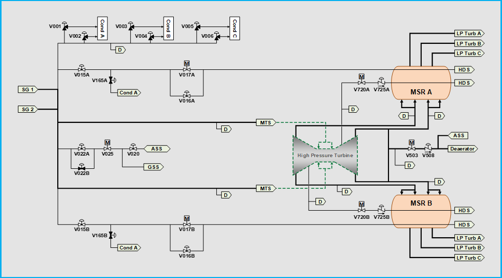
Simplified Diagram
To MSRs
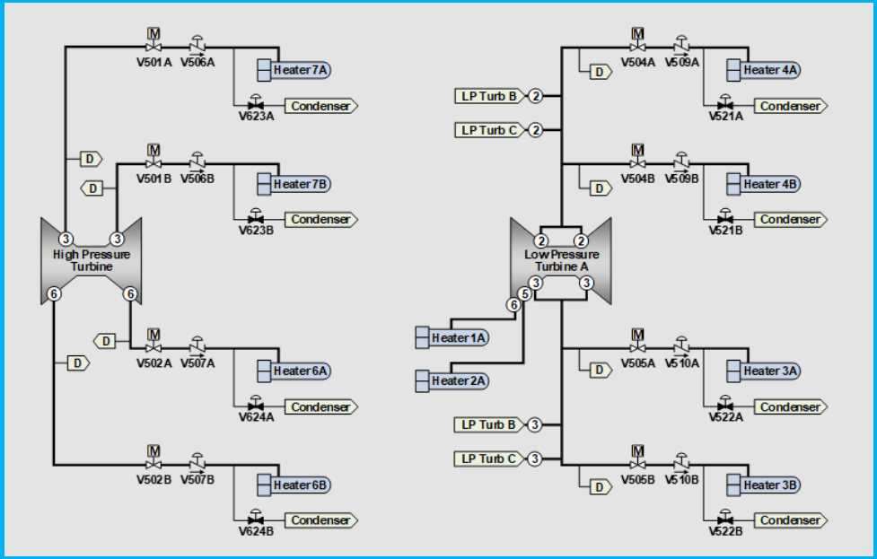
Simplified Diagram
MSRs to LPs
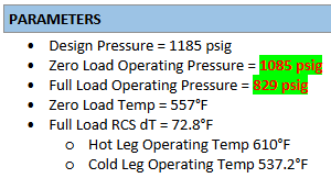
Nominal Parameters
Zero to Full Load
Zero: 1,085psig
Full: 830psig
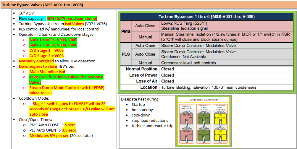
Bypass Valves
Capacity
PMS Isolation
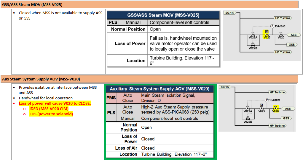
GSS/ASS Supply from Main Steam
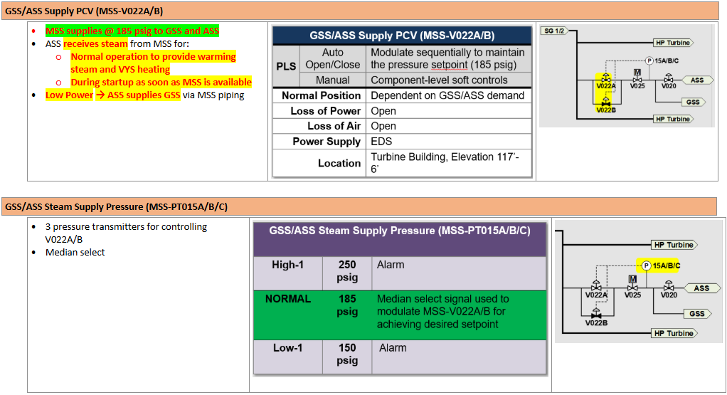
GSS/ASS Supply from Main Steam Cont.
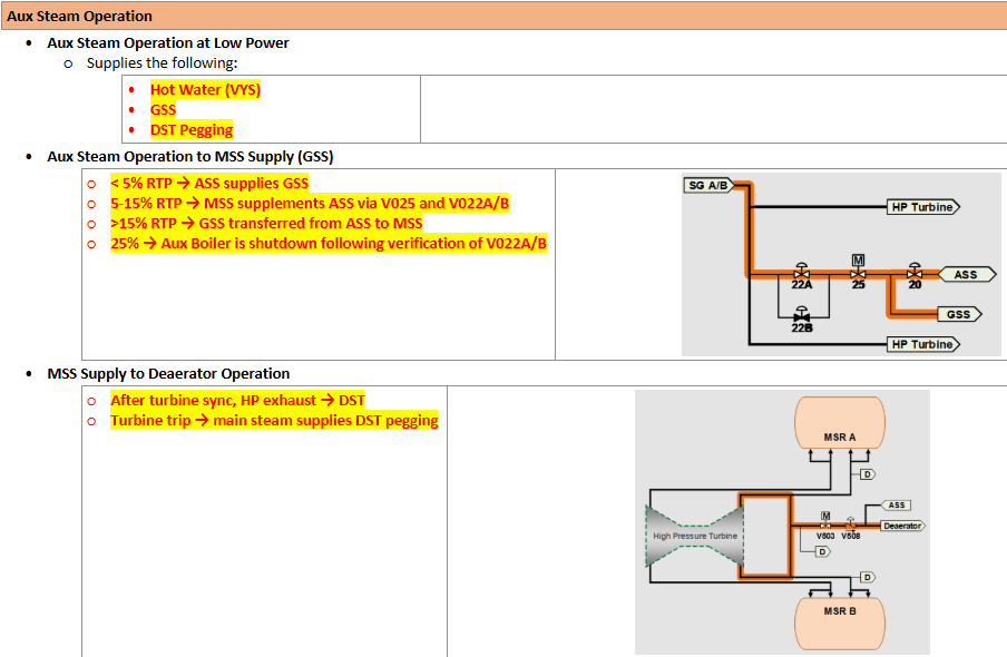
Aux Steam vs Main Steam Supply
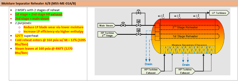
Moisture Separator Reheaters
Heater Stages supply
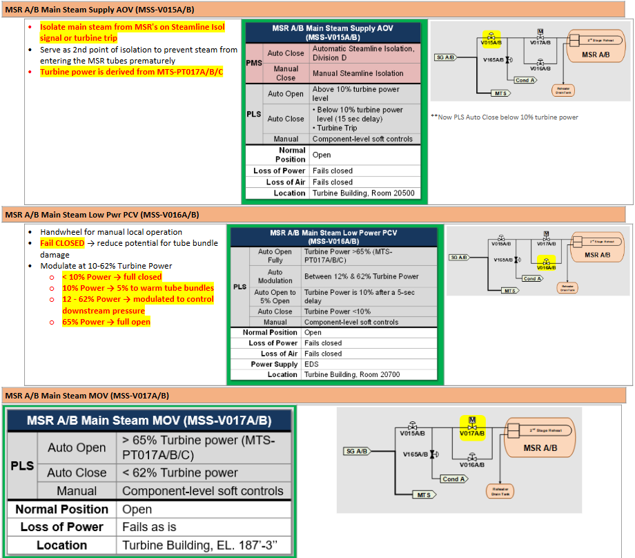
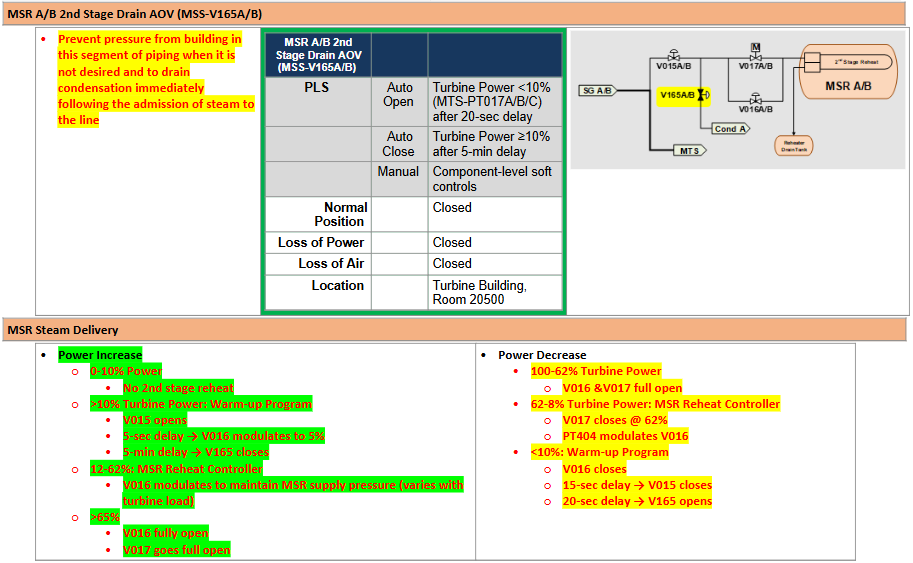
Main Steam to MSR
Sequence Power Levels
Main Steam to MSR
Sequence Power Levels Cont.
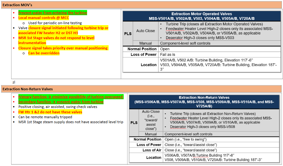
Extraction MOVs vs NRVs
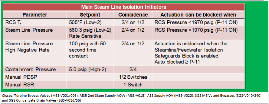
PMS Steamline Isolation Overview
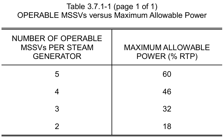
3.7.1 Main Steam Safety Valves (MSSVs)
Applicability *Note
Number of Operable MSSVs to Maximum Power Level
MODES 1, 2, 3, and 4
*Not required to be Operable for OPENING when on SDC
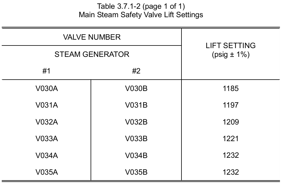
3.7.1 Main Steam Safety Valves (MSSVs)
Lift Settings
First Setpoint: Design Pressure of system
+12psig
+12psig
+12psig
+11psig
+0psig (same as previous)
3.7.2 Main Steam Line Flow Path Isolation Valves
LCO (Applicable Valves)
Applicability
MSIVs (5-10sec closure time)
MSIV Bypasses
MSL Drain valves
Turbine Stop or Control valves*
Bypass valves
MSR 2nd stage steam isolation valves
MODES 1, 2, 3, and 4
3.7.8 Main Steam Line Leakage
LCO
Applicability
MSL leakage through pipe walls INSIDE containment shall be ≤0.5gpm
MODES 1, 2, 3, and 4