Programmable Logic Controller
1/19
Earn XP
Description and Tags
Name | Mastery | Learn | Test | Matching | Spaced | Call with Kai | Chat |
|---|
No analytics yet
Send a link to your students to track their progress
20 Terms
Programming logic controller
Programmable Logic Controller (PLC) can be simply defined as a special computer used to control
industrial machines. Such machines are used for automation, that is, replacing human workforce by
technology and equipment. It is usually applied to perform repeating processes.
Being a controller, PLC has the capacity to power and control different output devices to perform
specific functions. By programming, PLC is integrated with a certain machine logic while performing such
functions.
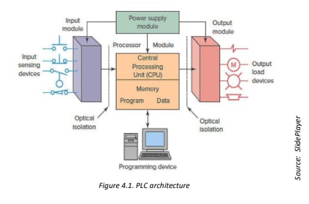
Components
Processor Module
Programming Device
Input Module
Output Module
Power Supply Module
Processor Module
Contains a memory, where the program is stored, and CPU, that makes decisions and executes control instructions based on the program instructions in memory.
Programming Device
Used to input the desired instructions. These instructions determine what the PLC will do for a specific input. Several methods are available in programming a PLC, where ladder programming is most common.
Input Module
Accepts a variety of digital and analog signals from various field devices and converts them into a logic signal that can be used by the CPU. Different kinds of switches, sensors and transducers are the primary devices under this module.
PLC Applications
Traffic Light System
Car Park Monitoring System
Bottling System
Process Control System
PLC Setup
(1) Input terminal with ten (10) ports – numbered 0 to 9, and (1) Output terminal with
six (6) ports – numbered 0 to 5. This model is powered by 24V dc power. The Serial port is used
to connect the PLC to a computer for programming and monitoring. Input indicators corresponds
to the input terminal. When a port is activated, its corresponding indicator lights up. Output
indicators have the same function. Status indicators tells the current status or operation of the
PLC. Power indicator indicates that the PLC is on. Run indicates when the PLC is doing its function
based on the program instruction. Fault indicates if the PLC detected error in the system and
connection. Force indicates if the input-output (IO) force functions are present or enabled.
PLC Programming
Instruction List
Structured Text
Ladder Diagram
Functional Block Diagram
Sequential Function Chart
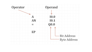
Instruction List
It is a text-based low-level type of programming language which is based on how the processor works. Instruction list is consisting of series of control instructions or commands like using machine code in microprocessor. Every instruction consists of an operator and an operand.
Structured Text
Considered as high-level programming language. A textual language based on the programming language PASCAL, BASIC or C. It is eventually used for more complex problems and data structures. It uses comprehensive constructs to allow a very compact formulation of the programming task and the ability to evaluate complex mathematical expression.
It offers the advantage that it allows a clear program structure. The disadvantage of this language is its lower efficiency. The programs are slower and longer.
Ladder Diagram
A graphical programming language which was referenced from circuit diagrams. It is combined with binary variables (digital logic operations) used for addressing, and it resembles thecircuit diagram of earlier relay control systems with contacts and coils.
Ladder logic is the main programming method used for PLCs and has been developed tomimic relay logic so that the amount of retraining needed for engineers and programmers wasgreatly reduced.
Functional Block Diagram
A graphical programming language referenced to the logic plans of electronic circuits. It is a graphical combination of different function elements.
In FBD, binary (digital) logic operations as well as timer, counter and comparator functions and program and module jumps can be displayed.
Sequential Function Chart
A flowchart-type of programming language that is used to structure controls programs to be processed sequentially in the form of cascaded sequence. It is mainly used for programming sequence-orientated control systems. It makes the graphic programming of a complex task in clear units possible. The control flow of these parts can be arranged gradually in sequential or parallel processes. It is also known as sequence cascade programming.
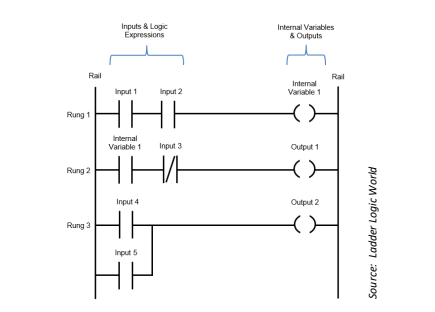
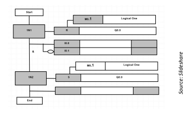
Ladder Programming
Rail
Rung
Branch
Instructions
Logical Continuity
The output device of a rung is energized if electric power can conceptually flow from the left side of the rung to the right side. Input devices are conditions, and if it is satisfied, the rung becomes true. Otherwise, inputs are assumed to block the flow of power. It is called logical continuity, if the left power rail has a continuous path of true condition to the output instruction.
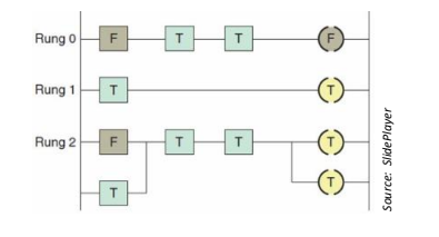
Basic Ladder Logic Instructions
Examine if Closed (XIC)
Examine if Open (XIO)
Output Energize (OTE)
Output Latch (OTL)
Examine if Closed (XIC) & Examine if Open (XIO)
Examine if Closed (XIC) - Represents a normally closed (NC) contact, or in true condition by default. When XIO is, its condition becomes false.
Examine if Open (XIO) - Represents a normally open (NO) contact, or in false condition by default. When XIC is activated, its condition becomes true.
Output Energize (OTE) & Output Latch (OTL)
Output Energize (OTE) - Represents any output device like motor or lamp, it is generally assumed as a coil. If the input conditions are true, OTE is activated.
Output Latch (OTL) - Similar to OTE, it represents any output device like motor or lamp. However, this instruction is activated when the input conditions are true, and remains activated even if the conditions becomes false.
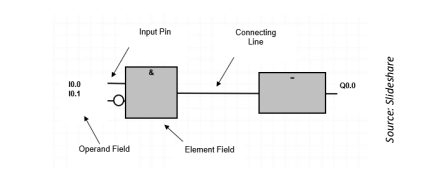
Instruction Addressing
While creating a PLC program, specific names are used to identify the instructions, similar to what is shown in preceding figures. These names function as the address of an instruction, and most of it corresponds to each port of the PLC I/O terminals
Instruction Type
Terminal Number
Port Number
Basic Logic Functions
AND Function – the output is ON only if both inputs are ON.
OR Function – the output is ON if any of the two inputs are ON.
NAND Function – the output is ON if any of the two inputs are OFF.
NOR Function – the output is ON only if both inputs are OFF.
XOR Function – the output is ON if any of the two inputs is ON, but not both.
XNOR Function – the output is ON only if both of the two inputs are either OFF or ON.
Set / Reset Latch using Momentary Switch – used for continuous loops.