CIS Exam 2 Study Guide
1/169
There's no tags or description
Looks like no tags are added yet.
Name | Mastery | Learn | Test | Matching | Spaced | Call with Kai |
|---|
No analytics yet
Send a link to your students to track their progress
170 Terms
Entity Relationship Model (ERM)
Forms the basis of an ERD
The ERD represents the conceptual database as viewed by the end user
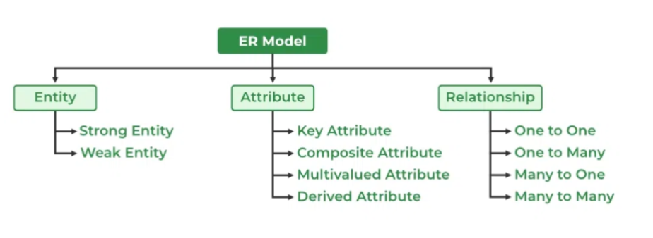
ERDs depict the databases’s main components:
Entities
Attributes
Relationships
Entities
An object of interest to the end user
Refers to the entity set and not to a single entity occurrence
An entity in the ERM corresponds to a table- not to a row- in the relational environment
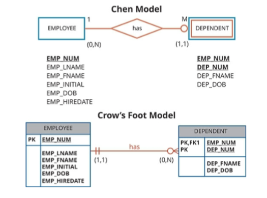
In Chen, Crow’s Foot, and UML notations, an entity is represented by a rectangle that contains the entity’s name
Entity name, a noun, is usually written in all capital letters
Existence Dependent
Entity that can exist in the database only when it is associated with another related entity occurrence
EX: an Order Item cannot exist without its parent entity
A mandatory foreign key that can’t be null is a key indicator of existence dependency
An entity is existence-dependent if it has a mandatory foreign key
Existence- Independent
If an entity can exist apart from all of its related entities
Referred to as a strong entity or regular entity
Weak Entity
Cannot be uniquely identified by its own attributes alone
Depends on a strong entity to be identified
Associated with an identifying entity
Required Atribute
An attribute that must have a value and cannot be left empty
Optional Attirbute
Does not require a value and can be left empty
Domain
Set of possible values for a given attribute
All attributes must have a domain
Identifier
One or more attributes that uniquely identify each entity instance
Composite Identifier
A primary key composed of more than one attribute
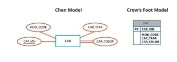
Simple Attribute
An attribute that cannot be subdivided
Single-Valued Attribute
An attribute that has only a single value
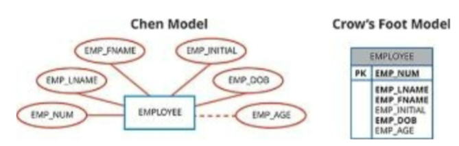
Derived Attribute
An attribute whose value is calculated from other attributes
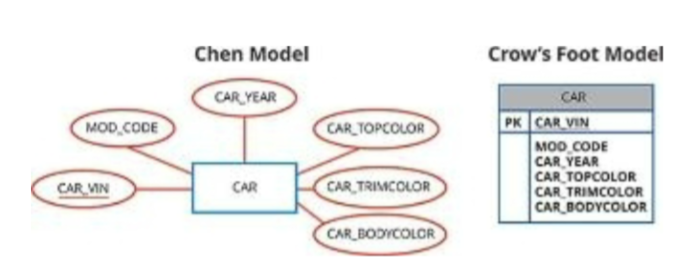
Composite Attribute
An attribute that can be subdivided to yield additional attributes
Multivalued Attributes
Attributes that have many values, an attribute consisting of more than one value for a given entity
Implementing Multivalued Attributes
Create several new attributes, one for each component of the original multivalued attribute
Create a new entity composed of the original multivalued attribute’s components
Multivalued Attribute in an Entity
Splitting the Multivalued Attribute into New Attributes
Depiction of a Derived Attribute
Relationships
Entities that participate in a relationship are also known as participants and each relationship is identified by a name that describes the relationship
Relationship name is an active or passive verb
Relationships between entities always operate in both directions
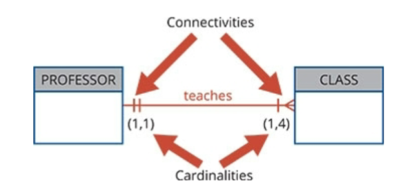
Connectivity
Describes the relationship classification
Includes 1:1, 1:M, and M:N
Cardinality
Expresses the minimum and maximum number of entity occurrences associated with one occurrence of the related entity
In the ERD, cardinality is indicated by placing the appropriate numbers beside the entities, using the format (x,y)
First value represents the minimum number of associated entities and the second value represents the maximum number of associated entities
Connectivity and Cardinality
Weak (Non-identifying) Relationships
Weak relationship exists if the primary key of the related entity does not contain a primary key component of the parent entity
Strong (Identifying) Relationships
A strong relationship exists when the primary key of the related entity contains a primary key component of the parent entity
Weak Entity Conditions
Entity is existence-dependent
Entity has a primary key that is partially or totally derived from parent entity in the relationship
The database designer usually determines whether an entity can be described as weak based on business rules
Optional Participation
Means that one entity occurrence does not require a corresponding entity occurrence in a particular relationship
If some courses are not enrolled by any of the students, the participation in the course will be partial
Mandatory Participation
One entity occurrence requires a corresponding entity occurrence in a particular relationship
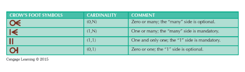
Crow’s Foot Symbols
Relationship Degree
Indicates the number of entities or participants associated with a relationship
Unary Relationship
Exists when an association is maintained within a single entity
Binary Relationship
Exists when two entities are associated
Ternary Relationship
Exists when three entities are associated
Recursive Relationship
A relationship within a single entity type
Can exist between occurrences of the same entity set (a condition naturally found within a unary relationship)
One common pitfall when working with unary relationships is to confuse participation with referential integrity
Similar because they are both implemented through constraints on the same set of attributes
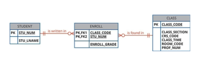
Associative (Composite) Entities
ER model uses the associative entity to represent an M:N relationship between two or more entities
Also called a composite or bridge entity and is a !:M relationship with the parent entities
Composed of the primary key attributes of each parent entity
The composite entity may also contain additional attributes that play no role in connective process
Developing an ERD
Create a detailed narrative of the organization’s description of operations
Identify business rules based on the description of operations
Identify main entities and relationships from the business rules
Develop the initial ERD
Identify the attributes and primary keys that adequately describe entities
Revise and review the ERD
Database Design Challenges: Conflicting Goals
Database designers must often make design compromises that are triggered by conflicting goals
Database design must conform to design standards
High processing speed may limit the number and complexity of logically desirable relationships
Maximum information generation may lead to loss of clean design structures and high transaction speed
A design that meets all logical requirements and design conventions is an important goal
Extended Entity Relationship Model
The result of adding more semantic constructs to the original ER model
Sometimes referred to as the enhanced entity relationship model
A diagram that uses the EERM is called EER Diagram (EERD)
Benefits of Grouping Employees into Various Types:
Avoids unnecessary nulls in attributes when some employees have characteristics that are not shared by other employees
Enables a particular employee type to participate in relationships that are unique to that employee type
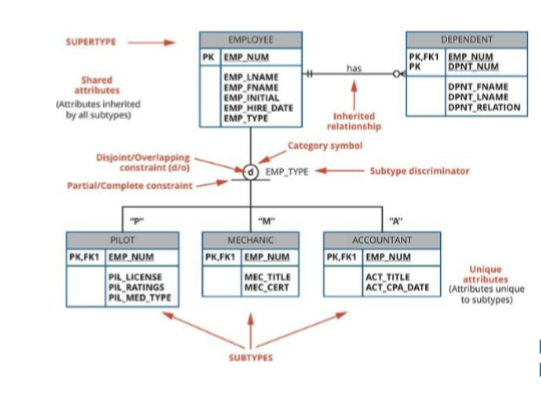
Entity Supertype
Generic entity type related to one or more entity subtypes
Entity supertype contains common characteristics
Contains unique characteristics of each entity subtype
Criteria to Determine when to Use Subtypes and Supertypes
There must be different, identifiable kinds of the entity in the user’s environment
Different kinds or types of instances should each have one or more attributes that are unique to that kind or type of instance
Specialization Hierarchy
Provides the means to do the following:
Support attribute inheritance
Define a special supertype attribute known as the subtype discriminator
Define disjoint or overlapping constraints and complete or partial constraints
Why is entity supertype used?
An entity supertype is a generic entity type that is related to one or
more entity subtypes, where the entity supertype contains the common
characteristics and the entity subtypes contain the unique characteristics of
each entity subtype. The reason for using supertypes is to minimize the number
of nulls and to minimize the likelihood of redundant relationships.
Inheritance
Enables an entity subtype to inherit attributes and relationships of the supertype
All entity subtypes inherit their primary key attribute from their supertype
At the implementation level, the supertype and its subtype(s) maintain a 1:1 relationship
Entity subtypes inherit all relationships in which supertype entity participates
Lower-level subtypes inherit all attributes and relationships from its upper-level supertypes
Subtype Discriminator
Attribute in the supertype entity that determines to which subtype the supertype occurrence is related
Default comparison condition for the subtype discriminator attribute is the equality comparison
In some situations the subtype discriminator is not necessarily based on an equality comparison
Disjoint Subtypes
Subtypes that contain a unique subset of the supertype entity set
Also known as nonoverlapping subtypes
Implementation of disjoint subtypes is based on the value of the subtype discriminator attribute in the supertype
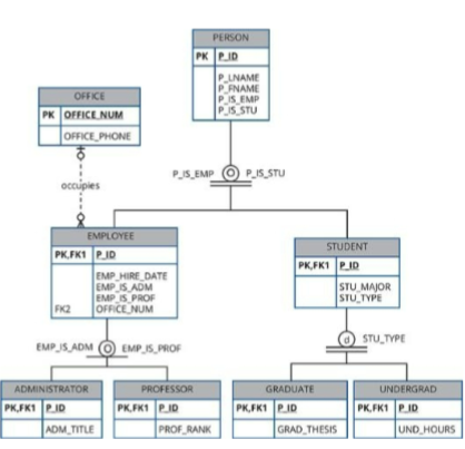
Overlapping Subtypes
Subtypes that contain nonunique subsets of the supertype entity set
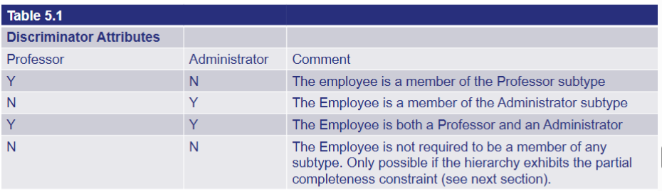
Implementation of overlapping subtypes requires the use of one discriminator attribute for each subtype
Discriminator Attributes with Overlapping Subtypes
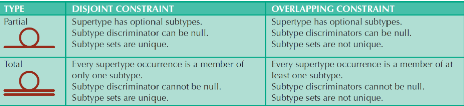
Completeness Constraint
Specifies whether each supertype occurrence must also be a member of at least one subtype
Partial Completeness
Not every supertype occurrence is a member of a subtype
Total Completeness
Every supertype occurrence must be a member of at least one subtypes
Specialization Hierarchy Constraint Scenarios
Specializtion
The top-down process of identifying lower-level, more specific entity subtypes from a higher-level entity supertype
Based on grouping unique characteristics and relationships of the subtypes
Generalization
Bottom-up process of identifying a higher-level, more generic entity supertype from lower-level entity subtypes
Based on grouping common characteristics and relationships of the subtypes
Entity Cluster
A “virtual” entity type used to represent multiple entities and relationships in the ERD
An entity cluster is formed by combining multiple interrelated entities into a single, abstract entity object
The general rule is to avoid the display of attributes to eliminate complications that result when the inheritance rules change
Entity Integrity: Selecting Primary Keys
Most important characteristic of an entity is its primary key (a single attributeor a combination of attributes), which uniquely identifies each entity instance
Primary key’s function is to guarantee entity integrity
Primary keys & foreign keys work together to implement relationships in the relational model
Importance of properly selecting the primary key has a direct bearing on the efficiency and effectiveness of database implementation
Natural Key/ Natural Identifier
Real-world identifier used to uniquely identify real-world objects
It is familiar to end users and forms part of their day-to-day business vocabulary
Usually, if an entity has a natural identifier, a data modeler uses it as the primary key of the entity being modeled
Primary Key Guidelines
Desirable Primary Key Characteristics:
Unique values
Non intelligent: no embedded semantic meaning
No change over time
Preferable single-attribute
Preferably numeric
Security-compliant
When to Use Composite Primary Keys
As identifiers of composite entities, in which each primary key combination is allowed once in M:N relationship
As identifiers of weak entities, in which the weak entity has a strong identifying relationship with the parent entity
Represents a real-world object that is existence-dependent on another real-world object
A real world object that is represented in the data model as two separate entities in a strong identifying relationship
Surrogate Key
Primary key created by the database to simplify the identification of entity instances
One advantage of a surrogate key is that because it has no intrinsic meaning, values for it can be generated by the DBMS to ensure that unique values are always provided
When to Use Surrogate Primary Keys
When there is no natural key
When the selected candidate key has embedded semantic contents
When the selected candidate key is too long
Time-Variant Data
Data whose values change over time and for which a history of the data changes must be retained
To model time-variant data, you must create a new entity in a 1:M relationship with the original entity
This new entity contains the new value, the date of the change, and any other pertinent attribute
Design Trap
Occurs when a relationship is improperly or incompletely identified, and is represented in a way not consistence with the real world
Most common design trap is known as a fan trap
Fan Trap
Occurs when you have one entity in two 1:M relationships to other entities
Produces an association among other entities not expressed in the model
Redundant Relaitonships
Occur when there are multiple relationship paths between related entities
Main concern is that they remain consistent across the model
Some designs use redundant relationships as a way to simplify the design
Normalization
A process for evaluating and correcting table structures to minimize data redundancies
Reduces the likelihood of data anomalies
Assigns attributes to tables based on determination
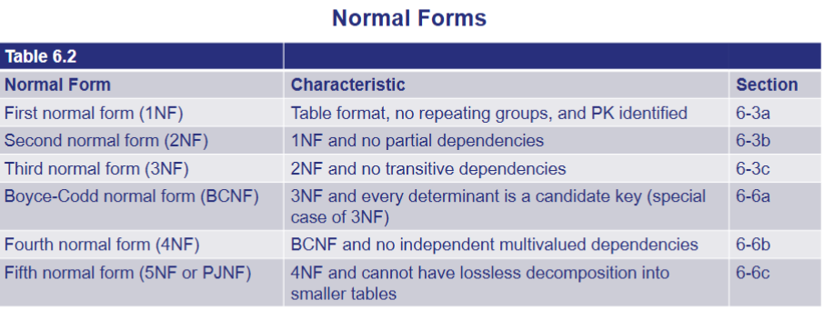
Normalization Stages
Stages are called normal forms
First three:
First Normal Form (1NF)
Second Normal Forms (2NF)
Third Normal From (3NF)
Database Tables and Normalization
From a structural point of view, higher normal forms are better than lower normal forms
For most purposes in business database design, 3NF is as high as you need to go in the normalization process
Denormalization
Produces a lower normal form
Result of denormalization is increased performance but greater data redundancy
Need for Normalization
Commonly used:
When designing a new database structure
To analyze the relationship among the attributes within each entity and determine if the structure can be improved through normalization
Goal of Normalization
To eliminate data anomalies by eliminating unnecessary or unwanted data redundancies
Uses the concept of functional dependencies to identify which attribute determines other attributes
Normalization Process
The objective of normalization is to ensure that each table conforms to the concept of well-formed relations and has the following characteristics:
Each table represents a single subject
Each row/column intersection contains only one value and not a group of values
No data item will be unnecessarily stored in more than one table
All nonprime attributes in a table are dependent on the primary key
Each table has no insertion, update or deletion anomalies
Objective in 3NF
Higher normal forms are better than lower normal forms
2NF is better than 1NF; 3NF is better than 2NF
For most business database design purposes, 3 NF is as high as we need to go in normalization process
Higher forms, such as 5NF and DKNF are not likely to be encountered in business environment
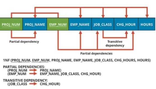
Partial Dependency
Exists when there is a functional dependence in which the determinant is only part of the primary key
The assumption is that there is only one candidate key
Partial dependencies tend to be straightforward and easy to identify
Transitive Dependency
Exists when the attribute is dependent on another attribute that is not part of the primary key
Transitive dependencies are more difficult to identify among a set of data
They occur only when a functional dependence exists among non-prime attributes
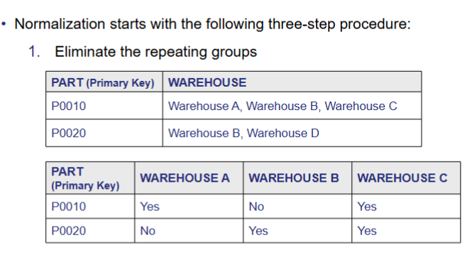
Conversion to First Normal Form (1NF)
A dependency diagram depicts all dependencies found within given table structure
It helps to get an overview of all relationships among table’s attributes
Their use makes it less likely that an important dependency will be overlooked
The term 1NF describes the tabular format in which the following occur:
All key attributes are defined
There are no repeating groups in the table
All attributes are dependent on the primary key
• All relational tables satisfy 1NF requirements
• Some tables contain partial dependencies
Dependency Diagram in Normalization
Depicts all dependencies found within given table structure
Helpful in getting bird’s-eye view of all relationships among table’s attributes
Makes it less likely that will overlook an important dependency
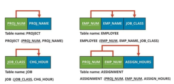
Conversion to Second Normal Form (2NF)
• Conversion to 2NF occurs only when the 1NF has a composite primary key
− If the 1NF has a single-attribute primary key, then the table is automatically in 2NF
• The 1NF-to-2NF conversion is simple, you take the following steps:
− Step 1: Make new tables to eliminate partial dependencies
− Step 2: Reassign corresponding dependent attributes
• A table is in 2NF under the following circumstances :
− When it is in 1NF
− When it includes no partial dependencies
Conversion to Third Normal Form (3NF)
• The data anomalies created by the database organization shown in Figure 6.4 are easily
eliminated by completing the following two steps:
− Step 1: Make new tables to eliminate transitive dependencies
− Step 2: Reassign corresponding dependent attributes
• A table is in 3NF under the following circumstances:
− When it is in 2NF
− When it contains no transitive dependencies
Issues to Address to Produce a Good Normalized Set
Minimize data entry errors
Evaluate naming conventions
Refine attribute atomicity
Identify new attributes
Identify new relationships
Refine primary keys as required for data granularity
Maintain historical accuracy
Evaluate using derived attributes
Atomic Attribute
An attribute that cannot be further subdivided
Atomicity
A characteristic an attribute that cannot be divided into smaller units
Granularity
Refers to the level of detail represented by the values stored in a table’s row
Surrogate Key Considerations
• Surrogate keys are used by designers when the primary key is considered to be unsuitable
• A surrogate key is a system-defined attribute generally created and managed via the DBMS
• Usually it is a numeric value which is automatically incremented for each new row
Higher-Level Normal Forms
• Tables in 3NF will perform suitably for business transactional databases
• Higher normal forms are sometimes useful
• This section covers the following higher-level normal forms:
− Boyce-Codd normal form (BCNF)
− Fourth normal form (4NF)
− Fifth normal form (5NF)
Boyce-Codd Normal Form
A table is in BCNF when it is in 3NF and every determinant in the table is a candidate key
• When a table contains only one candidate key, the 3NF and the BCNF are equivalent
• BCNF can be violated only when the table contains more than one candidate key
• BCNF is considered to be a special case of 3NF
Denormalization
• Important database design goals include the following:
− Creation of normalized relations
− Considering processing requirements and speed
• A problem with normalization is that as tables are decomposed to conform to normalization
requirements, the number of database tables expands
• Joining a larger number of tables takes additional input/output (I/O) operations and processing
logic, thereby reducing system speed
Defects in Unnormalized Tables
− Data updates are less efficient because tables are larger
− Indexing is more cumbersome
− There are no simple strategies for creating virtual tables known as views
• Unnormalized database tables often lead to various data redundancy disasters in production
databases
Data-Modeling Checklist, Business Rules
− Properly document and verify all business rules with the end users
− Ensure that all business rules are written precisely, clearly, and simply
The business rules must help identify entities, attributes, relationships, and constraints
− Identify the source of all business rules, and ensure that each business rule is justified,
dated, and signed off by an approving authority
Data Modeling Checklist, Data Modeling
− Naming conventions: all names should be limited in length (database-dependent size)
− Entity names:
Should be nouns that are familiar to business and should be short and meaningful
Should document abbreviations, synonyms, and aliases for each entity
Should be unique within the model
Composite entities may include a combination of abbreviated names of the entities linked through the composite entity
Data Modeling Checklist, Data Modeling Attributes
Should be simple and single-valued (atomic data)
Should document default values, constraints, synonyms, and aliases
Derived attributes should be clearly identified and include source(s)
Should not be redundant unless this is required for transaction accuracy, performance,
or maintaining a history
Nonkey attributes must be fully dependent on the PK attribute
Data Modeling Checklist, Data Modeling Entities
Each entity should represent a single subject
Each entity should represent a set of distinguishable entity instances
All entities should be in 3NF or higher
Any entities below 3NF should be justified
The granularity of the entity instance should be clearly defined
PK should be clearly defined and support the selected data granularity
Data Modeling Checklist, Data Modeling Relationships
Should clearly identify relationship participants
Should clearly define participation, connectivity, and document cardinality
Data Modeling Checklist, Data Modeling ER Model
Should be validated against expected processes: inserts, updates, and deletions
Should evaluate where, when, and how to maintain a history
Should not contain redundant relationships except as required (see attributes)
Should minimize data redundancy to ensure single-place updates
SQL Functions Fit into Several Categories:
Data Manipulation Language (DML)
Data Definition Language (DDL)
Transaction Control Language (TCL)
Data Control Language (DCL)
Transaction
A logical unit of work composed of one or more SQL statements
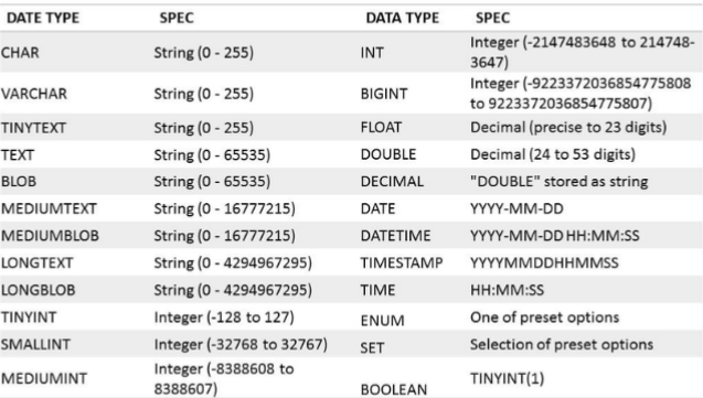
MySQL Data Types
SELECT Query
Specifies which data should be retrieved and how it should be filtered, aggregated, and displayed
Functions of Each Clause in a SELECT query
− SELECT – specifies the attributes to be returned by the query
− FROM – specifies the table(s) from which the data will be retrieved
− WHERE – filters the rows of data based on provided criteria
− GROUP BY – groups the rows of data into collections based on sharing the same values in
one or more attributes
− HAVING – filters the groups formed in the GROUP BY clause based on provided criteria
− ORDER BY – sorts the final query result rows in ascending or descending order based on
the values of one or more attributes