PTE Injection Molding
1/107
There's no tags or description
Looks like no tags are added yet.
Name | Mastery | Learn | Test | Matching | Spaced | Call with Kai |
|---|
No analytics yet
Send a link to your students to track their progress
108 Terms
Parts of a molding machine
Tie bars
Mold
Controller
Nozzle
Barrel
Heater Bands
Hopper
Screw Motor
Hydraulic Valve
Moveable Platen
Stationary Platen
Screw Position Indicator
Thermolator
Conditions to start mold cycle
Doors / Safety guards shut
Soak time complete
Mold in open position
Ejectors back
Screw at or beyond injection start position
Injection carriage forward w/nozzle in contact with mold
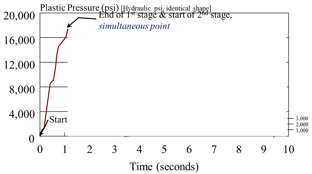
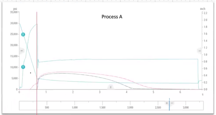
Label pressure output graph
X-axis = Time (seconds)
Fill time
Pack time
Pack Pressure
Injection pressure at transfer
Y-axis = pressure (psi) hydraulic or plastic
3 functions of molding machine injection unit
Heating (melts plastic)
Conveying (injections plastic)
Injecting (Pressurizes plastic)
Molding cycle phases
Mold close
1st stage filling
2nd stage pack and hold
Cooling —> Screw recovery delay, screw recovery, decompression
Mold open
Ejectors forward
Ejectors back
Why is pack pressure often limited in electric machines
High pressures requires high torque on the motor which could result in overheating and burning out the motor.
Why are 2-stage injection units often thought to be more precise
Screw does not reciprocate so heat history is more consistent
Plunger is less mass than a plasticizing screw so less overtravel
No check ring (eliminates variability)
Disadvantage: separate unit creates lots of bulk/length to injection unit so greater pressure loss through nozzle. Longer color changes.
3 zones of injection molding screw
Feed zone (deepest flight depth)
Compression zone - Most of the work done here. Squeezes pellets against barrel wall while rotating driving heat to melt plastic
Metering zone (shallowest flight depth. Fully flowable state to build shot)
Total injection forward time for a PARALLEL controller?
Injection time 6 sec
Pack time 4 sec
Actual fil time 1.3 sec
6 seconds
= Total screw forward time
Total injection forward time for a SERIES controller?
Injection time 6 sec
Pack time 4 sec
Actual fil time 1.3 sec
5.3 seconds
= set injection time limit
4 reasons sprue might stick to A side
Nozzle housing misaligned with sprue bushing (undercut to pull through tip)
Nozzle orifice larger than sprue diameter so can’t break free from nozzle tip
Incorrect sprue puller design
Sprue not cooled enough
Need 1in3/sec per cavity and going to 8 cavity mold. How does this impact choice of melt delivery system REGARDING PROCESS?
Hot or cold would need to support 8 in3/sec total. Cold would have bigger shot volume to maintain same vol flow rate so fill time would be longer
Need 1in3/sec per cavity and going to 8 cavity mold. How does this impact choice of melt delivery system REGARDING MACHINE?
Shot size vs machine capacity. Hot runners with small shot volume will lose process control. Cold runner with large shot volume may use all capacity
Minimum/maximum mold height and machine maximum daylight
Need larger screw diameter. One key factor regarding machine’s ability to mold based on larger screw diameter?
Machine max injection pressure. Screw diameter increase = injection pressure decrease which could interfere with parts ability to fill
Explain relationship between volumetric flow rate and larger screw diameter
Larger screw = increase volumetric flow rate = decreases mechanical advantage (intensification ratio)
Same force applied to a larger cross sectional area lowers plastic pressure capability and mechanical advantage
This lowers the injection pressure capacity
What force is clamp tonnage trying to overcome?
Must be greater than force acting on parting line of mold. Trying to overcome pressure needed to fill a specific part geometry/cross sectional area of cavity
Existing mold design and gate location cannot change. What 2 other factors will influence amount of clamp tonnage?
Material viscosity
Packing pressure
2 different parts with hot runner and same projected area onto parting line. Same material. Why might required clamp tonnage be different for the 2 parts?
Part thickness/geometry different for each of the parts
Material viscosity is different
Pressure distribution in the cavity — different gate location could lead to different flow lengths/pressure gradient during packing/filling
Experience lower injection pressure at transfer.
What changed in material?
Pressure in cavity?
Size of part?
Clamp tonnage?
Decreased
Increased
Increased
Increased
What is the recommended delta T for cooling systems?
<5°F or <2°F for critical dims
Identify nozzle tips
Full internal taper
General purpose
Nylon (reverse taper)
4 considerations when selecting nozzle
Material type/style
Length
Spherical radius
Orifice diameter
3 critical drying parameters
Residence time
Drying temperature
Dew point
Reasons why material might not be dry in desiccant dryer
Desiccant worn out or contaminated
Poor air flow
Wet desiccant at startup
Air flow not dispersed evenly within dryer
Bad moisture measurement
Blower motor turned backwards
2 concerns with a color change of same base material
Color package could impact nucleation
Colorant could have different viscosity
2 benefits of vacuum dryer
Decreased drying time (water boils out at lower temperature = faster and lower energy)
Reduces energy consumption
Why would using 87% of machine’s shot capacity lead to inconsistent processes?
Shorter residence time could risk unmelted pellets moving into compression zone of barrel leading to damage. Pellets could make it into part
How to improve chance of consistent parts if using 87% of machine shot capacity
Increase rear/midzone barrel temperatures to get heat in sooner/pre-heat the resin
Move to press with larger shot capacity
Put in 2-stage machine with plunger instead of reciprocating screw
New screw design
Within a family of materials, the higher the crystallinity the BLANK the melting point
Higher
Between families of materials, the most crystalline materials have the BLANK melting point
Lowest
Nylon 4/6 to Nylon 6/6 melt temperature should be BLANK
Decreased
Nylon 6/6 to Nylon 6 melt temperature should be BLANK
Decreased
Recommended temperature range for feed throat
130°F - 180°F
Avoids condensation but low enough to avoid binding from sticking/clumping
Running PVC material. What is one critical item of the screw you should review before you begin molding parts
Compression ratio. Different materials have different tolerances to shear heat which could lead to degradation
Explain how it might be possible to run above moisture limit and remain below 40% increase in MFI threshold for degradation
Lower residence time and lower melt temperature can tolerate some excessive moisture
Does AMORPHOUS or SEMI-CRYSTALLINE materials have a longer feed section in a screw. Why?
Semi-Crystalline. Take more energy to melt. Longer feed section will give more time for the material to melt before the compression zone
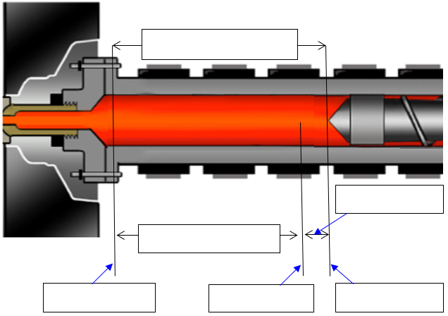
Label where the following are
Shot size
Decompression
Transfer Position
Fill Time
Shot Size Setting
Suck Back
Cut-off
Injection Start Position
Injection Time
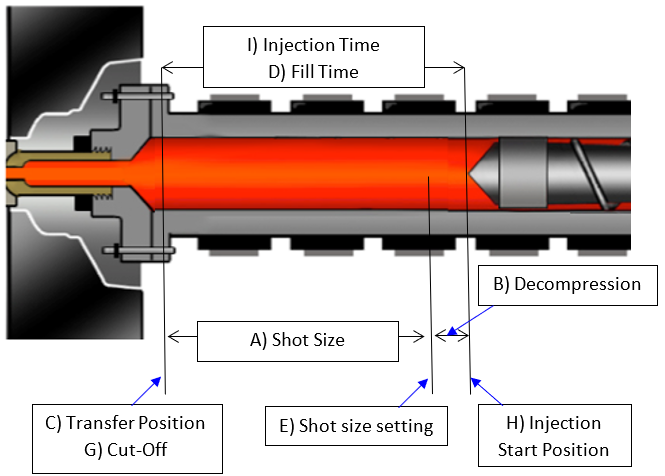
Theoretical Fill Time
= (Injected Volume) / (Volumetric Flow Rate Q)
OR
= (Injected Volume) / (Area * Injection speed)
Using Q, r, and Viscosity describe behavior of Hagen-Poiseuille graph
Slow fill times - thick frozen layer, viscosity increases = higher pressure. Very little shear thinning and shear heating
Medium fill times - viscosity decreases due to shear heating = lower pressure. Frozen layer decreases. Reductions in viscosity and frozen layer outweigh the increase in flow rate.
Fast fill times = Reductions in viscosity and frozen layer no longer outweigh the increase in flow rate
2 reasons why you may not want to begin your Fill Time Scan at max machine injection speed
Material degradation from over shearing
Damage the mold
Pressure limited at this speed
3 items to determine why fill time is no longer decreasing with faster speeds in Fill Time Scan
Achieved machine pressure limit
Met injection pressure limit
Machine cannot achieve set speed
Why not start at slowest speed during Fill Time Scan?
The faster you go, you gain momentum then the screw over travels and pushes more material into the mold (not safe for mold)
3 reasons to adjust transfer position during Fill Time Scan
Can see almost entire part every time to assess part filling and cosmetics
Better indication of mold, machine, and material capability
Less risk of parts sticking and mold damage. Can check for sticking at 95%
Adjust transfer will take place on next shot. Adjusting shot size setting may cause an error when it picks up the shot.
2 key factors to consider when setting injection pressure limit
Machine delta P
Normal viscosity variation
What is Delta P? Why is it important?
Machine’s pressure drop (Difference between set injection pressure limit and peak pressure during injection).
Important to understand so you’re not pressure limited without knowing it. Prefer mold to stop when there’s an issue instead of keep going until machine limit is hit.
Simulation pressure greater than reality. Nozzle accounted for. Why?
Simulation doesn’t account for screw overtravel which can cause different perceived 95% full parts. Simulation fills to 99% every time. Reality it does not.
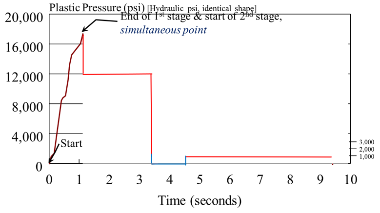
Complete graph for pack and hold, cooling, screw delay and recovery
Pack P 12,000 for 2.5 seconds
1 second screw delay
Back pressure 750 psi
Screw recovery ends at 9.5 seconds at 200 RPMs
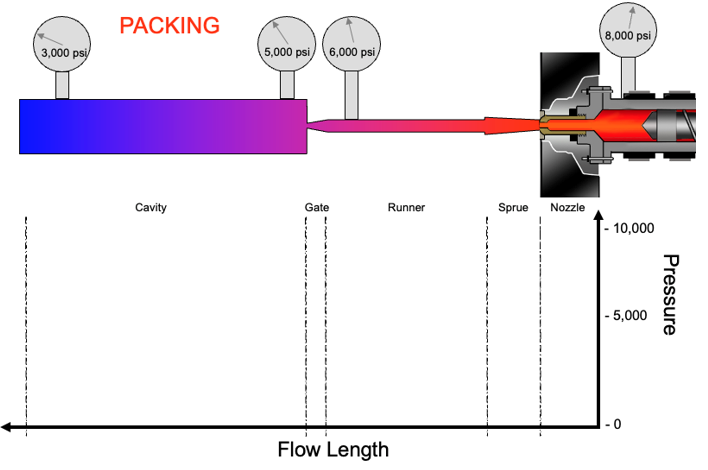
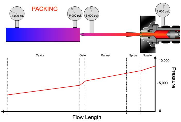
Draw pressure vs flow length line during pack and hold
Why would you run WITHOUT gate seal?
Relieve pressure and minimize stress at the gate which can be a failure point. May get better part performance if relieve pressure. May have more uniform shrink or reduce the shrink/warp.
Why would you run WITH gate seal?
Pressurize cavity to prevent material flow out which could lead to sink or voids.
2-Cavity mold artificially balanced for filling by tweaking a runner diameter feeding one of the cavities. Why might variations in cavity pressure exist between cavities during packing?
Weight balancing ensures cavities are filled to the same % full at the same time but they are not evenly packed out. Different pressure drops to each cavity so imbalanced packing which will lead to one cavity just packed out and the other one with flash/sticking

Sink on parts can’t eliminate with pack pressure without flash. Root cause related to PROCESS?
Low cushion
Pack velocity limited
Clamp tonnage set too low or not enough available
Pressure removed before gate was sealed
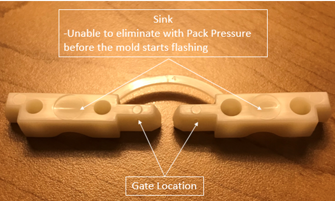
Sink on parts can’t eliminate with pack pressure without flash. Root cause related to MOLD?
Gate location on thin wall - Move
Gate too small and freezing before pack done
Ejector pin mark - no cooling & in thick area
Mold damage leading to flash before pressure
What studies are completed in the workbook?
Fill time scan
Pressure drop study
Pack pressure scan
Pack time scan
As you increase pack pressure to find the “Highest Acceptable Pack Pressure” you notice that as the pack pressure increases it is having no effect on the molded parts. What could cause this to happen?
No cushion left. Safe startup shot size calculations help prevent this.
When is gate seal on graph?
Part weight no longer gets heavier - go to next point even if weight increase looks small
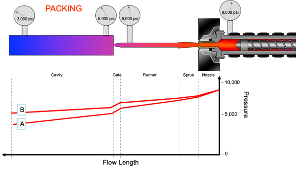
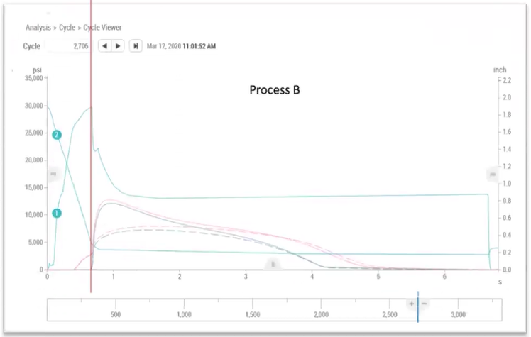
What changed to cause pressure gradient B?
Viscosity decreased

Why didn’t pressure at the nozzle change?
It’s a setpoint

How to adjust process to match B to A at end of cavity?
Decrease pack and hold time.
Can decrease injection speed and melt temperature to adjust viscosity but these can have significant side effects

When changing process to match B to A, what values from process sheet would you match?
Cavity pressure output
Fill only part weight
Critical dimensions
What is underdamped? What will the parts be like?
Pressure drops below set point
Parts will be under packed, lighter, smaller, sink, voids
What is overdamped? What will the parts be like?
More pressure during transfer so see more pressure in cavity
Parts will be over packed, heaving, larger, flash, stick
How to tell if plastic or hydraulic pressure on graph?
Hydraulic will be 2-3,000 psi or less
Plastic will be greater
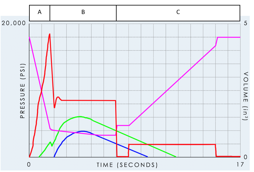
List 3 things happening in region C
Cooling
Screw Recovery
Suck back
Screw Delay

Describe what is happening with screw position over time
Turn 90°
Injection rate (slope)
Transfer position screw moves forward to pressurize/compensate for material shrinkage
Remove pack/hold pressure so screw springs back due to material compression
Delay to allow pressure to bleed off
Recover rate (slope)
Suck back to start position
If viscosity increases, how does FILLING pressure react?
Increase
If viscosity increases, how does CLAMP TONNAGE react and why?
Decrease
Lower cavity pressure
How to address an increase in viscosity?
Manipulate of compensate for viscosity
Easier to compensate
Manipulate: Inject faster (should have already studied) or raise barrel temperature (increase likelihood of degradation, increase cooling time/cycle time, takes time to raise temp)
Compensate: Decrease transfer position slightly and increase pack/hold pressure. Match cavity pressure, part weight, and/or critical dimensions —> Viscosity UP = Pressure to fill UP = Compression of material UP = screw bounce UP = fill cavity less during filling
Explain why flow grouping root cause is either shear or steel variation
Delta P = (8 Q l n) / (pi r4)
8 & pi are constants
Q is controlled by machine
l, n, and r are the remaining variables which are related to shear or steel
What mold design characteristics determine number of flow groups
Number of cavities
Number of gates
Runner layout (balanced?)
Part geometry relative to gate
Comparing data BETWEEN flow groups, what are you looking for?
Rheological variations
Comparing data WITHIN A flow group, what are you looking for?
Steel variations
Within a group should receive about the same melt properties
# Flow groups =
# Total cavities / # cavities in FG 1
# Regions =
= cavities in FG 1
2 reasons to fill 80% visually during mold balance analysis?
Reduce flow front hesitation effects
Avoid overfilling the cavity skewing the analysis
2 reasons to ignore recommendation to fill 80% visually during mold balance analysis?
Terminate flow before living hinge (flow front hesitation)
May need more than 80% to eject the part out especially in stripper plate so don’t have to dig each part out.
What are the risks to collecting shot weights directly out of a hot runner manifold without shooting into the cavities themselves?
Safety (purging hot material)
Damage to hot runner system causing a leaking issue
Damage to face mounted gate inserts due to excessive pressure behind them - Resulting force could blow the insert out of the mold
Reviewing flow grouping analysis data and it indicates parts in the region to the right of the sprue are heaving. What should you consider?
Hot sprue? What kind of tip? Ported could have inconsistencies
Is data average or just one shot?
Shot to shot consistency?
If consistent, verify runner sizing, venting
4 PLASTIC VARIABLES
Plastic melt temperature
Plastic cooling rate and time
Plastic pressure gradient
Plastic flow rate
5 process outputs
Recovery time
Cycle time
Pressure at Transfer
Cushion
Fill time
Why monitor recovery time?
May indicate worn screw or barrel
Screw turns until it hits shot size setting so material in barrel is sheared differently which can change melt temperature
Why monitor cycle time?
Process consistency
Why monitor cushion?
Shot size consistency
Short shot if low
Flash if high
Check ring issues
Why monitor fill time?
1st stage flow rate setting consistency
Why monitor pressure at transfer?
Assesses viscosity shifts (moisture, new lot of resin, heater band out, etc.)
Submitted parts are too small. What outputs and settings should you evaluate?
Outputs
Cushion (shot size consistency)
Transfer pressure (viscosity shift)
Cavity pressure sensors (if available)
Mold temperature
Settings
Pack pressure
Transfer position (still correct?)
Mold temperature
Moisture content
Other
Flow rate
Nozzle
Cooling circuits hooked up correct and correct flow rate
Cycle time varying 1-2 seconds over 30 shots with 30% regrind. What outputs and settings should you evaulate?
Outputs
Recovery time (regrind sizing)
Cycle time
Settings
Back pressure (may not feed material properly)
Feed throat temperature
Other
Regrind composition/degradation/sizing
Feed throat actual temperature - needs to be cleaned?
Mold open/close time (machine issue)
Hydraulic Pressure - Machine or Plastic Variable?
Machine
Velocity (in/sec or mm/sec) - Machine or Plastic Variable?
Machine
Fill Time - Machine or Plastic Variable?
Plastic
Shot Size (mm, cm, in) - Machine or Plastic Variable?
Machine
Shot Size (mm3, cm3, in3) - Machine or Plastic Variable?
Plastic
Barrel Temperatures - Machine or Plastic Variable?
Machine
Plastic Temperatures - Machine or Plastic Variable?
Plastic
Machine or Plastic Variable?
Hydraulic Pressure
Pressure in the Nozzle
Velocity (in/sec or mm/sec)
Fill Time
Shot Size (mm, cm, in)
Shot Size (mm3, cm3, in3)
Barrel Temperatures
Part Temperature
M
P
M
P
M
P
M
P
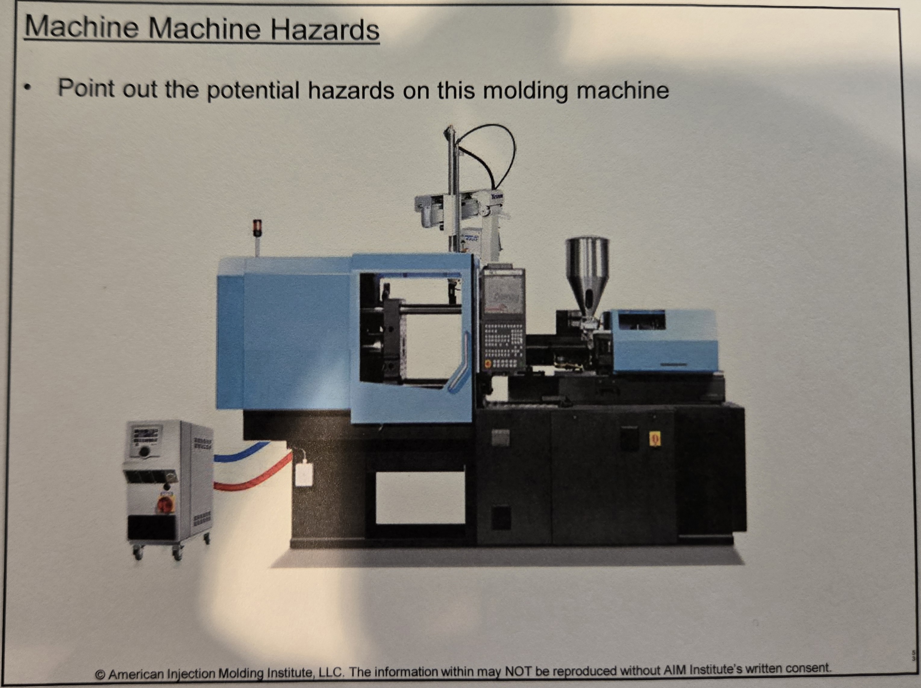
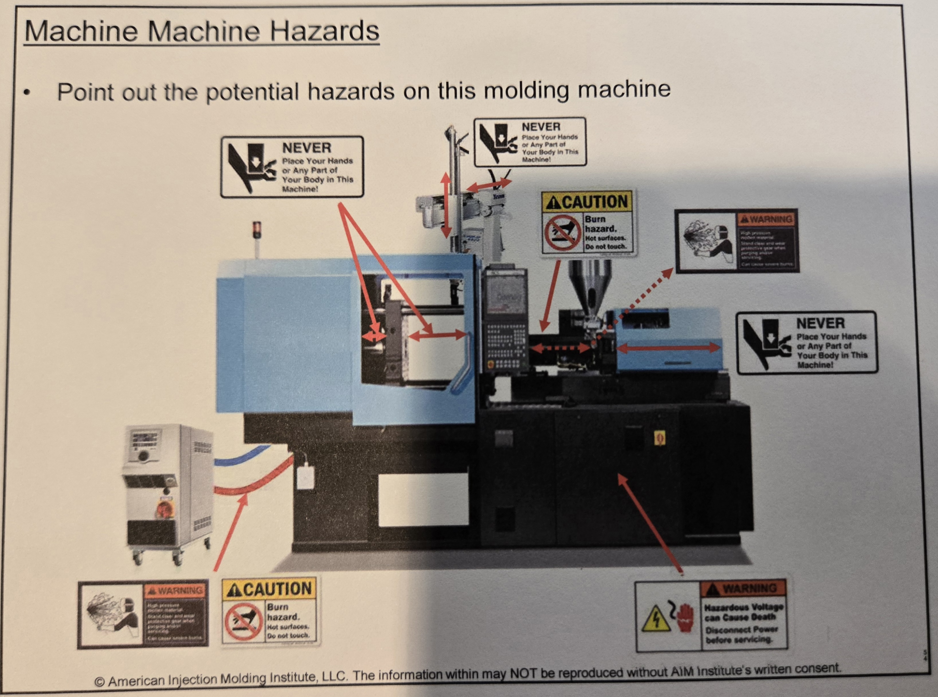
Identify potential hazards on this molding machine
Never place your hands or any part of your body in this machine
Caution Burn hazard. Hot surfaces. Do not touch.
Warning high pressure
Warning hazardous voltage can cause death
How are tie bars used to allow the clamp force to be maintained on the mold
As the moveable platen comes forward and applies clamp force, the force is transmitted to the stationary platen which forces the tie bars to stretch ever so slightly so the clamp force is applied to the mold face.
Advantage and disadvantage of reciprocating screw
Advantage: Single parrel. Plasticizing & plunger in one unit = less bulk = less pressure drop
Disadvantage: All pellets may not receive same heat history. Check ring is a wear item that needs to seal or you could have an inconsistent shot and run out of cushion. Mass of screw to move forward can over travel when it goes to transfer
Ejection stroke vs Mold open stroke
Ejection - enough to push part out (subtract wall thickness)
Mold open - 2.5*Part height + sprue height above part