1725 Computed Radiography
1/50
There's no tags or description
Looks like no tags are added yet.
Name | Mastery | Learn | Test | Matching | Spaced | Call with Kai |
|---|
No analytics yet
Send a link to your students to track their progress
51 Terms
Computed Radiography
The first commonly used digital system
Work flow is very similar to film/screen work flow
Can be used interchangeably with any radiographic imaging system
CR creates a latent image and uses the IR to store electrons in high energy traps
How are patients radiographed for computed radiography
Patient is radiographed exactly the same way as in conventional radiography.
Patient is positioned using appropriate positioning techniques
Cassette is place on the tabletop or within the bucky
Patient is exposed using the proper combination of kVP mAs and distance
Film/Screen Flowchart
Circuit → Tube → Beam → Subject → IR → Chemicals → View Box
Digital Radiography Flowchart
Circuit → Tube → Beam → Subject → IR → Computer → Display Monitor
Computed Radiography Flowchart
Circuit → Tube → Beam → Subject → IR → Reader → ADC → Computer → Display Monitor
IP
Imaging Plate
PD
Photodiode
PMT
Photomultiplier Tube
PSL
Photostimulable Luminescence
PSP
Photostimulable Phosphor
SP
Storage Phosphor
SPS
Storage Phosphor Screen
Two stage image acquisition
Latent image captured on PSP plate
Multiple images are allowed
Image data extracted in reader
Analog light conversion
Each plate is separate file in the computer
No matter how many images are on the plate
Even double exposure errors
Photostimulable Luminescence
The property of a material where light is emitted in response to external stimulation
Can be immediate; also can emit light at a later time when exposed to a different light source
Photostimulable Phosphors
Have the PSL property and are used to “store” the latent image in CR
Made of barium fluorohalide
Combined with europium as an activator
Responsible for the storage property of PSL
When x-ray interacts with barium fluorohalide atoms
They produce metastable electrons (Latent image occurs in the form of metastable electrons)
When metastable electrons return to ground state
Visible light is emitted
What stimulates returning to ground state
Exposing phosphor to intense infrared light from a laser
Why do SPS appear white
Because the small PSP particles scatter light (turbid)
SPS are
Mechanically stable
Electrostatically protected
Fashioned to optimize the intensity of stimulated light
CR Imaging Plate
Houses the PSP screen
Rugged cassette
CR can be substituted for screen film radiography and used with any x-ray system
Contains lead backing that reduces backscatter x-rays
Improves contrast resolution of the image receptor
Imaging plate barcode label
Cassette contains a barcode label on the cassette or the imaging plate viewed through a window on the cassette
Label enables technologist to match the image information with the patient identifying barcode on the exam request
PSL is similar to what
Optically stimulated luminescence (OSL)
Optically stimulated Luminescence (OSL)
One of the main radiation monitors
Light emitted with OSL crystal is illuminated
Thermoluminescent Dosimetry (TLD)
One of the main radiation monitors
Light emitted when TLD crystal is heated
Light stimulation-emission process Expose
The first of a sequence of events that results in an x-ray induced image forming signal
X-ray beam Exposes PSP
Energy transferred results in excitation of electrons
~50% of electrons return to ground state immediately = prompt emission of light
Remaining electrons return to ground state over time
Causes image ot fade
CR signal loss is objectionable after approx 8 hours
Light stimulation-emission process Stimulate
Stimulation of the latent image results from the interaction of a infrared laser beam with the photostimulable phosphor
Diameter of the laser beam determines spatial resolution of the CR system
As laser intensity increases, intensity of emitted signal (Image) increases
As laer beam penetrates, it spreads
Spread increases with PSP thickness
What does Laser stand for
Light Amplification by Stimulated Emission of Radiation
The laser
Creates and amplifies a narrow intense beam of coherent light
Requires a constant power source to prevent output fluctuations
Laser beam passes through beam-shaping optics to an optical mirror, which directs the laser beam to the surface of the imaging plate
Light Stimulation- Emission Process Read
The light signal emitted after stimulation is detected and measured
Laser beam causes electrons to return to ground state
Emission of shorter wavelength light in blue region of visible spectrum
Some signal is lost
Scattering of emitted light
Collection efficiency of photodetector
Photodiode are the light detector for CR
Light Stimulation-Emission Process Erase
Final step
Before plate reuse, any residual metastable electron are moved to the ground state by an intense light
The stimulation cycle does not return ALL electrons to ground state
If residual image remained causes ghosting
Any residual latent image is removed by flooding the phosphor with very intense white light from fluorescent lamps
Light Stimulation-Emission Process Erase Continued
The process of reading the image returns most of electrons to a lower energy state
Reading effectively removes the image from the plate
Imaging plates are extremely sensitive to scatter radiation
Plates should be erased to prevent a buildup of background signal
Plates should be run at least once a week under an erase cycle to remove background radiation and scatter
Systems automatically erase the plate by flooding it with light to remove any electrons still trapped after the initial plate reading
Cassettes should be erased before use if the last time of erasure is unknown
The CR PSP is sensitive to background radiation and can become fogged
The CR reader Mechanical features
CR inserted
IP is removed and fitted in a precision drive mechanism
Slow scan
The precision drive mechanism moved IP constant but slow along the long axis
Fast Scan
A deflection device (rotated polygon or oscillating mirror) deflects the laser beam back and for across IP
Optical features of the CR reader
Laser
Beam shaping optics
Light collecting optics
Optical filters
Photodetector
Laser
The source of stimulating light
Requires a constant power source to prevent output fluctuations
Small laser beam diameter = high spatial resolution
Beam Shaping Optics
Laser beam passes through beam shaping optics to an optical mirror, which directs the laser beam to the surface of the imaging plate
The more angles the beam, the more elliptical the shape of the beam
If this change in the beam shape were ignored, output of the screed would differ from the middle to the edges
Result would be differing spatial resolution and inconsistent output signal depending of the position and angle of the laser beam
To correct, beam is “shaped” by special optics that keep the beam size, shape, and speed largely independent of the beam position
Light collecting optics and optical filters
Emitted light (signal) from IP is channeled into a funnel like fiber optic collection assembly
Light is filtered before photodetection
Removed long wavelength stimulated emission light (noise)
Emitted light from the IP is the signal, stimulating light is the noise
Improves signal to noise ratio
Improves contrast resolution
Photodetector
The light is directed to the photomultiplier/charged coupled device that converts the light to an electronic signal
That electronic signal is digitized by an analog to digital converter (ADC)
The CR Reader Computer Control
Output of the photodetector is a time varying analog signal that is transmitted to a computer system
Sampling - Time between samples
Quantization - Value of each sample
Sampling and quantization are the tow processes of analog to digital conversion (ADC)
Spatial Resolution
How resolved your image is, how clear the image is, ability to distinguish parts from one another, how clear an edge is
Contrast Resolution
Visual differences from the shading, differences in all the shades of grey
Noise
A problem, comes in every piece of equipment because we have to convert. The goal is to reduce the amount of noise. It will affect the differences in the greys, it will add or detract from your image
Artifacts
Anything added to the image that’s not supposed to be there (ex: A scratch)
Dynamic Range
The number of grey shades that an imaging system can reproduce
Wide latitude
More leeway, allows for a bigger margin of error
Imaging characteristics
CR has large dynamic range and wide latitude
A 14 bit CR image has 16,384 grey levels
More tissue densities on the digital radiograph are seen in CR giving the appearance of more detail
Image receptor response function
Spatial resolution: Refers to the amount of detail present in any image
For example, an AP knee radiograph typically does not show soft tissue structures on the lateral aspects of the distal femur or proximal tibia or fibula
An AP knee digital image shows not only the soft tissue but also the edge of the skin. This is due to the wider dynamic recording range and does not mean that there is additional detail
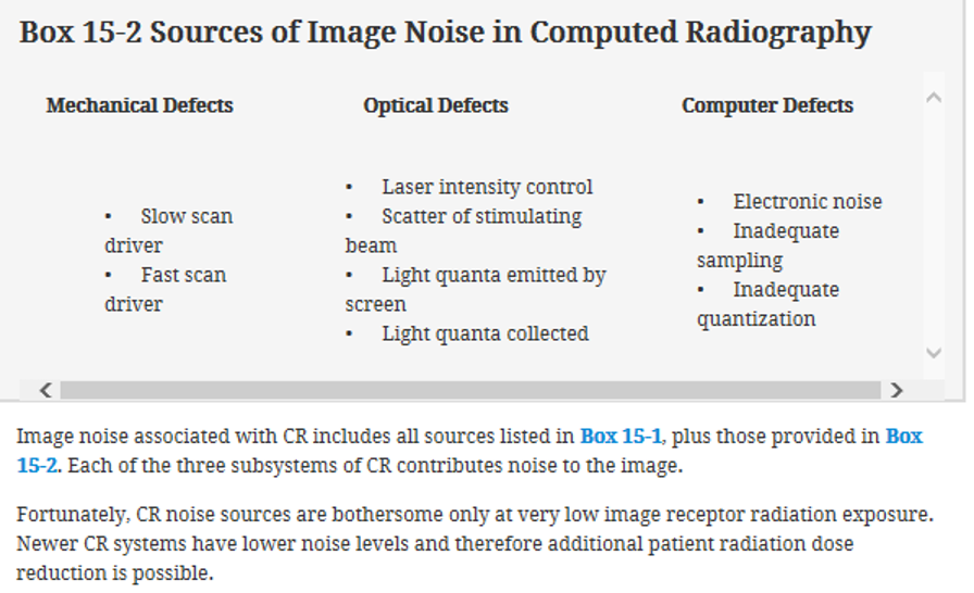
Image noise
Principle source is scatter radiation no matter what image receptor used
Patient radiation dose
CR is faster IR compared to film screen systems
CR should be performed at lower techniques than film screen radiography
Remember that increasing kVp will allow a decrease in mAs needed and will decrease exposure to the patient. Both the mAs that is necessary and the appropriate kVp value helps keep the dose ALARA