Arithmetic Logic Unit (taken from Chap. 4)
1/29
There's no tags or description
Looks like no tags are added yet.
Name | Mastery | Learn | Test | Matching | Spaced | Call with Kai |
|---|
No analytics yet
Send a link to your students to track their progress
30 Terms
register transfer language
encompasses the following:
the set of registers a digital computer contains and their functions
the set of micro-operations that can be done on the binary data stored in each register
the control signals that initiates the sequence of micro-operations
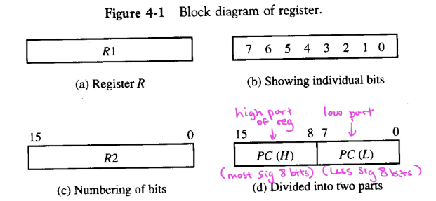
registers in the ALU
P(H) → H stands for HIGH, aka the “higher “ portion of the bits stored in the register
P(L) → L stands for LOW, aka the “lower portion of the bits stored in the register
basic symbols / notation for register transfer
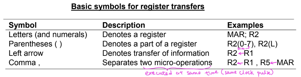
control signal for register transfer → what does the statement P : R2 ← R1 mean?
if (P = 1), then (R2 ← R1)
see “Summary of Chapter 4” notes, page 1 for a labelled diagram of the circuit logic behind this
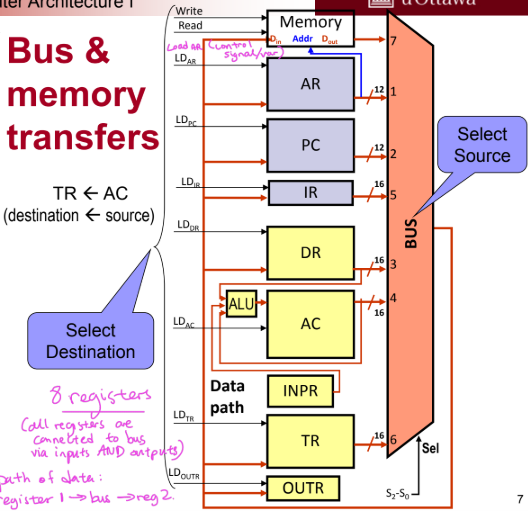
bus and register/memory transfers
every register is connected to the bus to allow registers to “communicate” with each other
the bus controls the “control inputs” and the transfer of info between registers
the register with LD = 1 is the DESTINATION of the data
the register sending data into the bus through the multiplexer system is the SOURCE of the data
basic logic diagram of a common bus with multiplexers
see “Summary of Chapter 4” notes, page 2
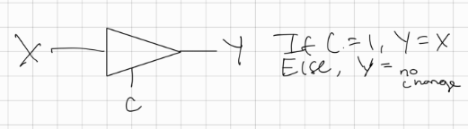
three-state buffer
the state where the output would have no change is called the “high impedance state”
the high impedance state makes the gate behave like an open circuit (as if the output of the gate is “disconnected” from the input of the gate. hence resulting in no change in the output no matter what the input was)
logic circuit of ONE bus line using three-state buffers
see “Summary of Chapter 4” notes, page 3
memeory transfer
a memory word is denoted by “M”
the address register holding the memory address of the word to be accessed in memory is denoted by AR (one of essential registers in any basic computer system)
the data register to hold the word to be read from or written into memory is denoted by DR
memory read operation: READ: DR ← M[AR]
the statement translates to: if the control function/signal READ is 1, then transfer the data of the word from the memory address stored in register AR into the register DR
memory write operation: WRITE: M[AR] ← DR
if the control function/signal WRITE = 1, then transfer the word (data bits) stored in register DR into the memory location whose address if stored in the register AR
types of micro-operations
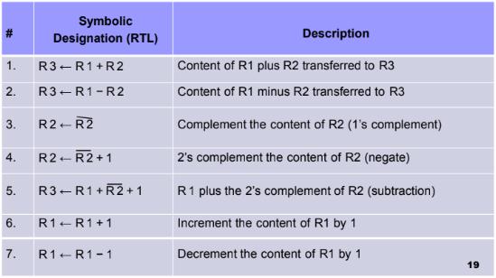
arithmetic → performing arithmetic operations like addition and subtraction on the data stored in registers
logic → performing boolean operations on data stored in registers
shift → performing shift operations on the bits of the data stored in registers
register transfer → transferring data between registers or between a register and the memory unit (which is made up of registers)
common arithmetic micro-operations
arithmetic circuit (AC): design procedure
see “Summary of Chapter 4” notes, page 2
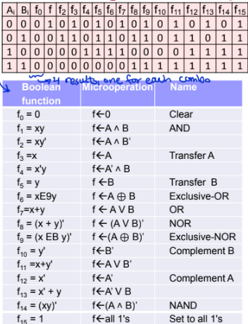
list of all possible 16 logic operations that can be performed on pairs of bits from two registers
logic circuit/unit (LC): design procedure
see “Summary of Chapter 4” notes, page 6
real-life applications of logic micro-operations
logic micro-operations are mainly used to manipulate individual bits/portions of a word stored in a register
examples:
selective-set
selective-complement
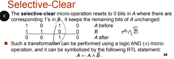
selective-clear
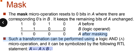
mask
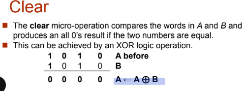
clear
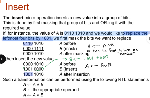
insert
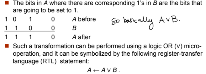
applications of using logic micro-operations to manipulate a set of bits: selective-set
defn: setting certain bits of A to 1 and leaving the other bits of A unchanged
the equivalent logic operation to achieve selection-set is A OR B
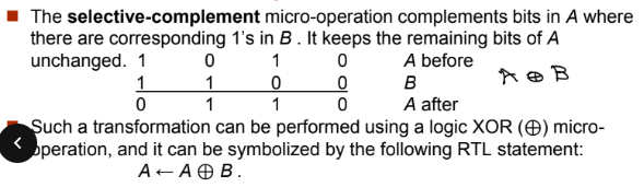
applications of using logic micro-operations to manipulate a set of bits: selective-complement
applications of using logic micro-operations to manipulate a set of bits: selective-clear
applications of using logic micro-operations to manipulate a set of bits: mask
applications of using logic micro-operations to manipulate a set of bits: clear
applications of using logic micro-operations to manipulate a set of bits: insert
three types of shift operations
logical shift
circular shift
arithmetic shift
all shift micro-operations and their notation/symbol
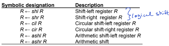
types of shift operations: logical shift
see “Summary of Chapter 4” notes, page 7
types of shift operations: circular shift
see “Summary of Chapter 4” notes, page 8
types of shift operations: arithmetic shift
an arithmetic shift is a micro-operation that shifts a SIGNED number left or right
the shift must be done in a way so as to not change the value of the SIGN BIT
see “Summary of Chapter 4” notes, page 9
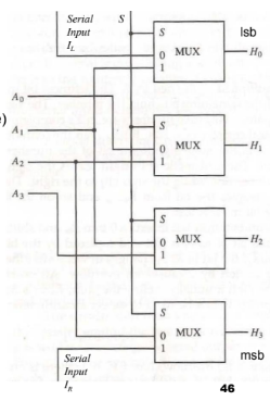
left/right shift circuit implementation
ALU circuit (arithmetic + logic unit combined)
see “Summary of Chapter 4” notes, page 10