Mass Analyzers
1/37
There's no tags or description
Looks like no tags are added yet.
Name | Mastery | Learn | Test | Matching | Spaced | Call with Kai |
|---|
No analytics yet
Send a link to your students to track their progress
38 Terms
Mass Analyzer
central component within the mass spec instrument that separates ions based on their m/z ratios
Separates, filters, or traps ions based on their specific values using electric or magnetic fields
Defines the resolution, mass range, and sensitivity of the mass spectrometer
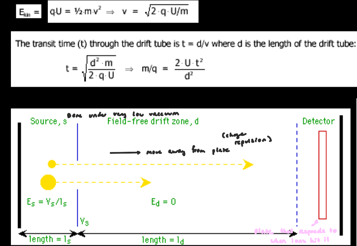
Time of Flight
a mass analyzer that separates ions based on how long they take to travel a fixed distance
often paired with ion sources like MALDI (MALDI-TOF) or ESI
all ions are given the same kinetic energy, so their speed depends on m/z ratio (e.g. ping pong vs bowling ball)
lower m/z (lighter ions) → move faster
higher m/z (heavier ions) → move slower
done in a vacuum to prevent ions from colliding w/ gas molecules
collisions w/ gas molecules would sow ions down and change their flight time
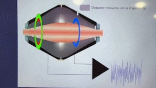
Time of Flight: How it works
ions are generated (ion source) and accelerated by an electric field
ions travel thru a flight tube toward a detector
a plate detects when ions hit it
the instrument records the exact time ions are accelerated and the time they hit the detector, which gives TOF
ions arriving at the same time = same m/z
Time of Flight Requirements for Accuracy
distance must be known
if flight path is longer, small differences in ion speed result in longer differences in arrival time → improves accuracy
time measurement must be prescise
operates under vacuum
temperature control is important (prevents expansion affecting distance)
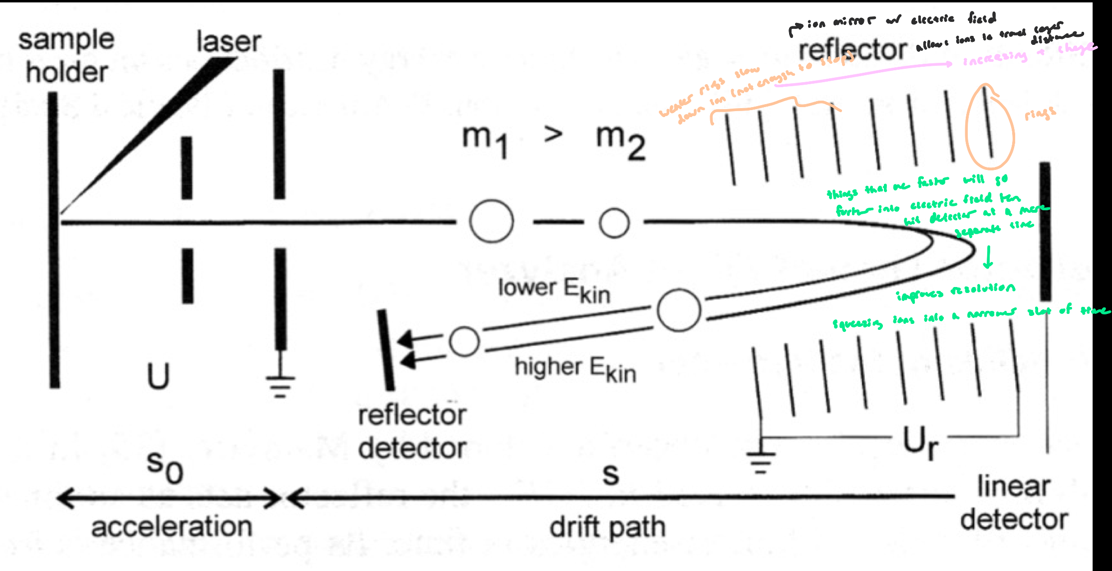
TOF Ion Mirror
a region with increasing (+) electric potential
acts like a mirror that slows, stops and reverses ions
ions enter the reflectron w/ diff kinetic energies
faster ions penetrate deeper into the electric field; travel a longer path before turning around
slower ions penetrate less deeply; travel a shorter path
ions w/ the same m/z but diff speeds would normally arrive at different times but are corrected to arrive closer together (signal is narrower)
e.g. ions starting at slightly diff positions in the source and the electric field isn’t perfectly uniform
TOF Ion Mirror
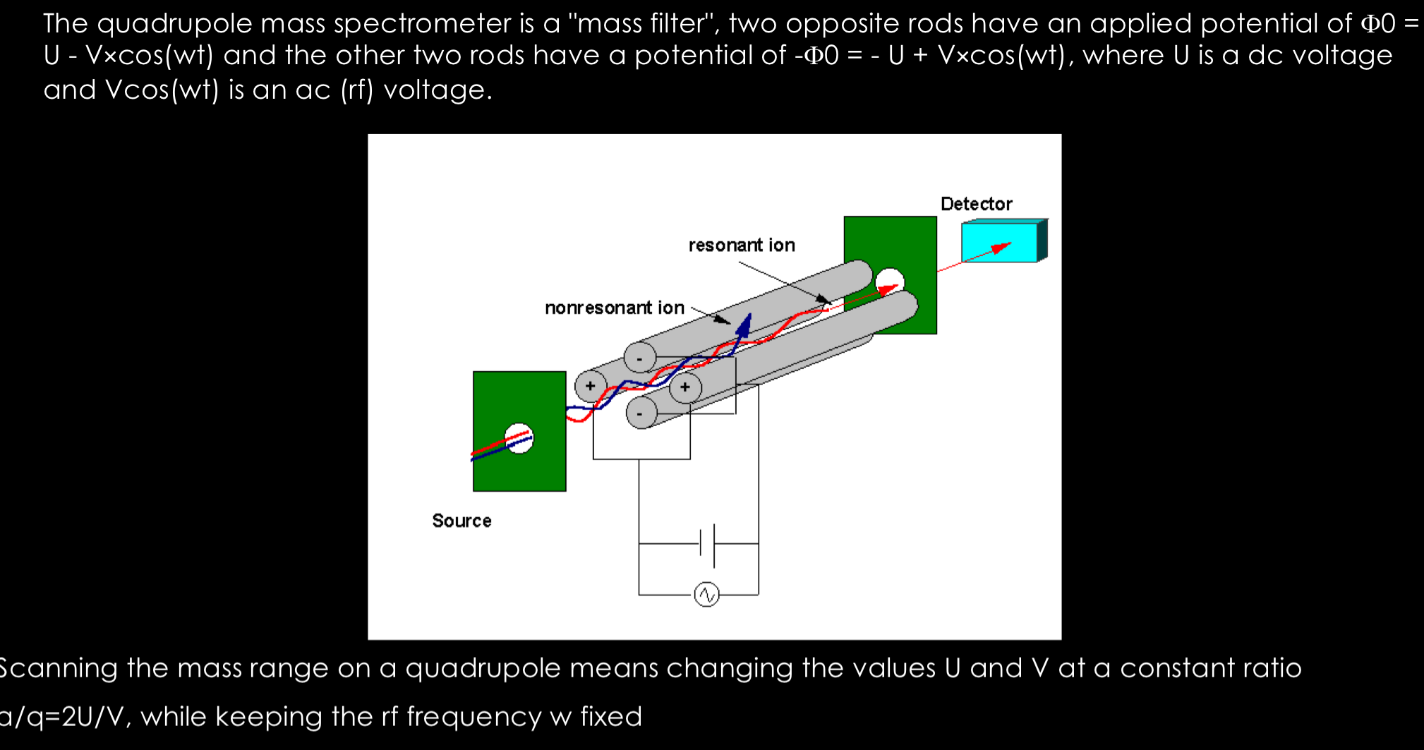
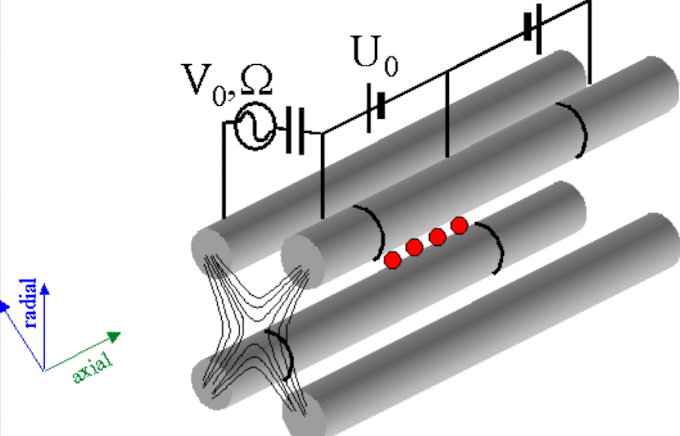
Quadropole Mass Analyzer
mass analyzer that acts as a mass filter
consists of 4 rods w/ applied voltages and opposite rods are paired:
two rods: + (U+RF voltage)
two rods: - (U+RF voltage, opposite sign)
ions travel between the ოთხ rods
a combination of DC voltage (U), oscillating RF voltage (V cos(ωt)) creates a dynamic electric field (electric field b/w the rods oscillates)
Quadropole Mass Analyzer: Key Principle
only ions w/ a specific m/z will have a stable path and pass thru
correct m/z → stable oscillation → passes thru
incorrect m/z → unstable path → collides w/ rods
Quadropole: Voltages
DC Voltage (U): a constant voltage, sets a steady electric field bias between opposite rods
Helps determine overall ion stability region
RF Voltage (V cos(ωt)): A rapidly oscillating voltage; alternates in time at frequency ω
Continuously changes the electric field direction/strength
without it, ions would drift and crash into rods
Combined effect: Rods carry a superposition of DC + RF voltage
This creates a time-dependent (dynamic) electric field
Quadropole: Changing the Voltages
by changing U and V (but keeping a constant ratio), diff m/z values become stable
allows the instrument to scan across masses
Why keep ratio constant? Ensures the shape of the stability region stays the same
Quadropole Parameters: a/q
a/q = 2U/V: determines ion stability in the quadropole
Combines: U = DC voltage (constant field contribution) and V = RF voltage amplitude (oscillating field contribution)
a/q defines which m/z ions have stable trajectories
Only ions with the correct balance of DC vs RF influence pass through
Quadropole Parameters: ±Φ₀ (±F₀)
Refers to the electrical potential on the rods
Rod pairs are set to opposite values
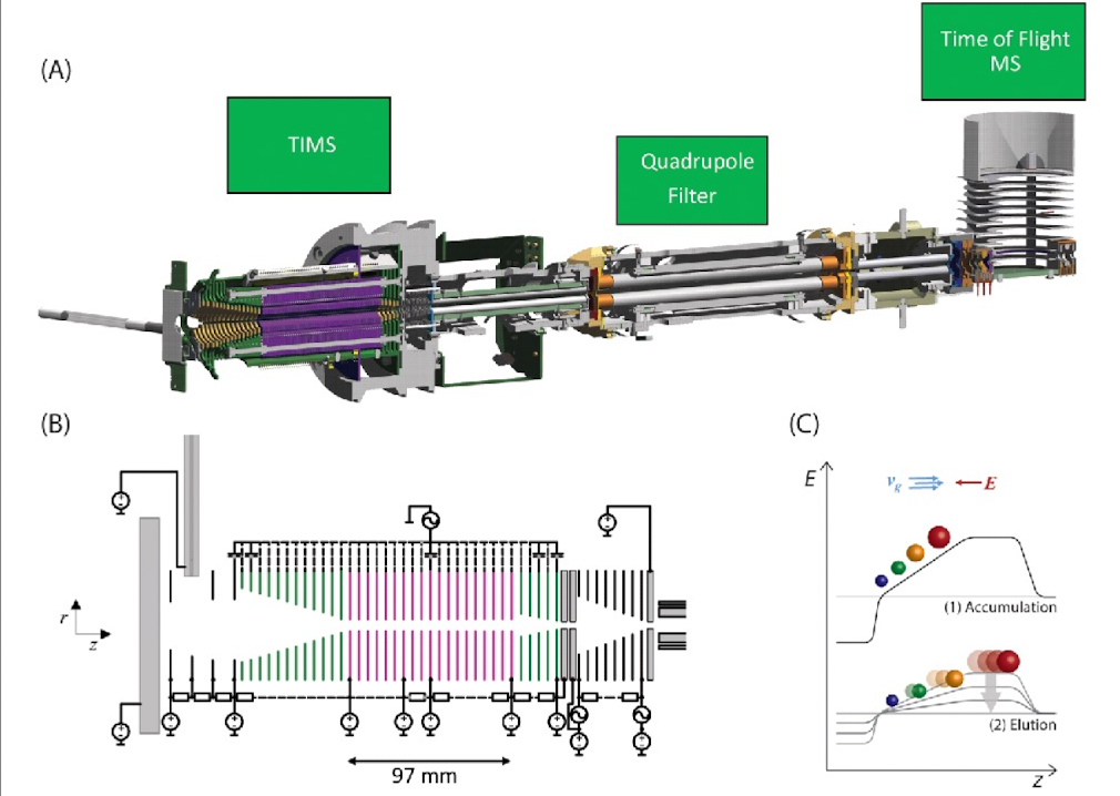
Trapped Ion Mobility
a technique that separates ions based on how they move thru a gas under an electric field
uses a controlled gas environment inside a vacuum gradient (small amount of gas is introduced, but instrument is still under high vacuum)
ions travel thru this region and repeatedly collide w/ gas molecules
“trapped”: ions are temporarily held and separated in a mobility region and then released in a more separated and organized way
Trapped Ion Mobility: Key Principle
ion motion depends on m/z and size/shape
smaller/lower m/z ions collide more w/ gas and lose more velocity → slower overall
larger/higher m/z ions have more momentum and are less effected by collisions → move faster
Trapped Ion Mobility + Time of Flight
Trapped ion mobility has limited resolution
it spreads out ions based on mobility and then feeds them into TOF mass spec, which improve separation and increases overall resolution
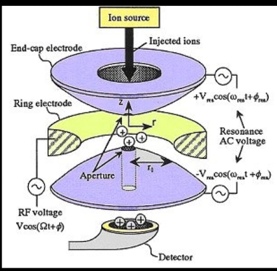
Quadropole Ion Traps
use radio-frequency (RF) electric fields to create regions were ions can be stably trapped in space depending on their m/z
instrument gradually changes RF conditions, and ions become unstable at specific m/z thresholds
unstable ions are ejected from the trap, they hit the detector and the signal recorded
stable ions stay trapped
3D Quadropole Ion Trap
has a ring electrode (middle), and two end-cap electrodes (top and bottom)
RF voltage are applied to create a 3D trapping field
the voltages continuously oscillates in polarity over time
ions are confined to a single central trapping region
2D Quadropole Ion Trap
four rods arranged like a quadropole
walls at both ends (end electrodes)
RF field trap ions in a line along the center axis
ions are confined radially, but an move along the axis unless capped
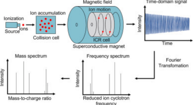
Fourier Transform-Ion Cyclotron Resonance: Key Principle
ions are trapped in a strong magentic field and forced into circular motion (cyclotron motion)
the frequency of this motion depends on mass-to-charge ratio (m/z)
a Fourier Transform (mathematical tool) converts detected signals into a mass spectrum
Fourier Transform-Ion Cyclotron Resonance: Why ions move in a circle
in a magnetic field, moving charge particles experience a force
this forces causes ions to move in a circular orbit
smaller m/z → faster motion
larger m/z → slower motion
Fourier Transform-Ion Cyclotron Resonance: Ion Excitation
Ion excitation: process where electrons within an atom or ion absorb energy, causing them to move to higher energy levels without leaving the particle
ions are excited in FT-ICR using a radiofrequency (RF) pulse
this increases their orbital radius and synchronizes motion
motion frequency depends on m/z
creates a stronger signal that can be detected
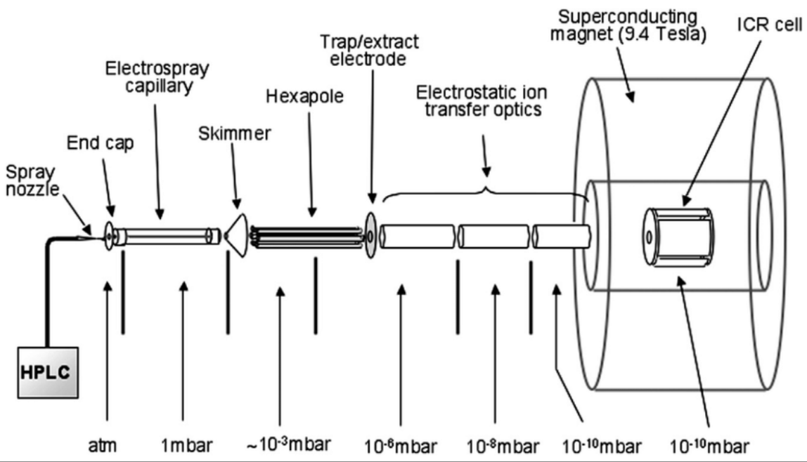
Fourier Transform-Ion Cyclotron Resonance: Vacuum Conditions
requires the lowest (most extreme) vacuum among mass analyzers
prevents ion collisions
allows ions to orbit for long periods → high resolution
the only thing that limits the time period is collisions with gas molecules
when ions collide, they lose energy and their motion becomes less coherent → signal decays faster
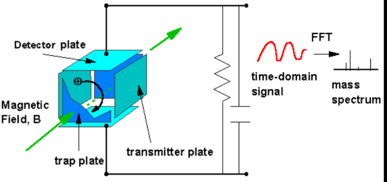
Fourier Transform-Ion Cyclotron Resonance: Detector Plates
metal plates placed on either side of ion motion
detect induced current as ions pass by; their motion causes a change in electric field, which induces a small current in the plates
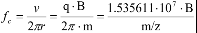
Cyclotron Frequency Equation
frequency depends on magnetic field (B): ↑ B => ↑ frequency & mass to charge (m/z): ↑ m/z = ↓ frequency
frequency = how fast an ion completes one full circle
the detector measures a wave (frequency signal), and that frequency is plugged into the equation to determine m/z
FT-ICR Figure
Orbitrap: Core Idea
mass analyzer
ions are trapped in an electric field (no magnet)
they oscillate in space (back and forth along central spindle axis, while also rotating it) at frequency that depends only on m/z
that motion produces a detectable current signal
easier to use than FT-ICR b/c no need for strong magnet, and still achieves high resolution via frequency detection
Orbitrap: Structure
central spindle-shaped electrode with a surrounding outer electrode
ions are injected into the space between them
the electrodes are typically oppositely charged
Orbitrap: Signal Generation
as ions oscillate, they induce a current in the outer electrode
this produces a time-domain decay signal (called an image current)
the signal decays b/c ions spread out in phase (exact position of each ion in its oscillation at a given moment) over time and don’t all oscillate perfectly together forever
at first, ions are in phase (moving tgt in sync), but over time, tiny differences make them drift apart
when ions are in phase their signals add up strongly
when they become out of phase, their signals start cancelling each other out
Orbitrap: Are they high yield?
Yes! The measured frequency depends only on [figure]
lower m/z → higher frequency
higher m/z → lower frequency
![<p>Yes! The measured frequency depends only on [figure]</p><ul><li><p>lower m/z → higher frequency</p></li><li><p>higher m/z → lower frequency</p></li></ul><p></p>](https://assets.knowt.com/user-attachments/fcfa92b7-1038-4c38-840a-80d0518183f1.png)
Orbitrap: What determines resolution in Orbitrap?
how long the ion signal can be measured before it decays
longer measurement → more precise frequency → higher resolution
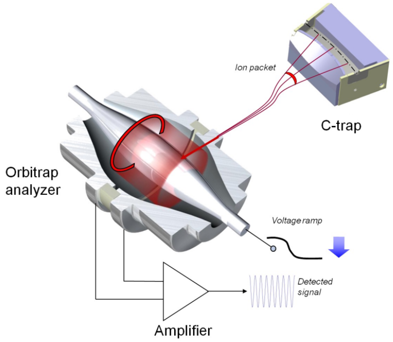
Orbitrap Figures