Eng Graphics - chapters 1-9
1/213
There's no tags or description
Looks like no tags are added yet.
Name | Mastery | Learn | Test | Matching | Spaced |
|---|
No study sessions yet.
214 Terms
What is design?
A strategic approach to problem solving
A sketch
Quick freehand drawing thats purpose is to communicate a design
How do you communicate your completed design that
needs to be manufactured or used as a legal document?
Create a technical/engineering drawing
what is a technical engineering drawing?
a set of drawings that communicate an idea, design, schematic, or model that fully and clearly define requirements for an engineered part or system
provide tolerancing, annotations, parts lists, etc. essential for manufacturing and quality control
What is the variation within each field of engineering’s drawings?
Electrical engineers draw circut schematics and circut board layouts
civil engineers draw plans for bridges and road layouts
Mechanical engineers draw parts and assemblies that need to be manufac
what is CAD’s brief history?
made in 1982 by John Walker
Solidworks brief history?
made in 1993 by Jon Hirschtick (first with 3D modeling)
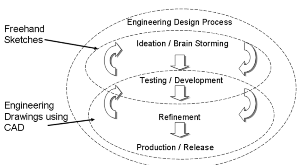
What are the four key stages of the engineering design process
What are the two main organizations that set blueprint standards?
ASME and ISO(International Organization for Standardization)
Technical drawings in the past were blue T/F?
True
What are the Drawing aspects of blueprints?
what are the Engineering Drawing Format and Contents?
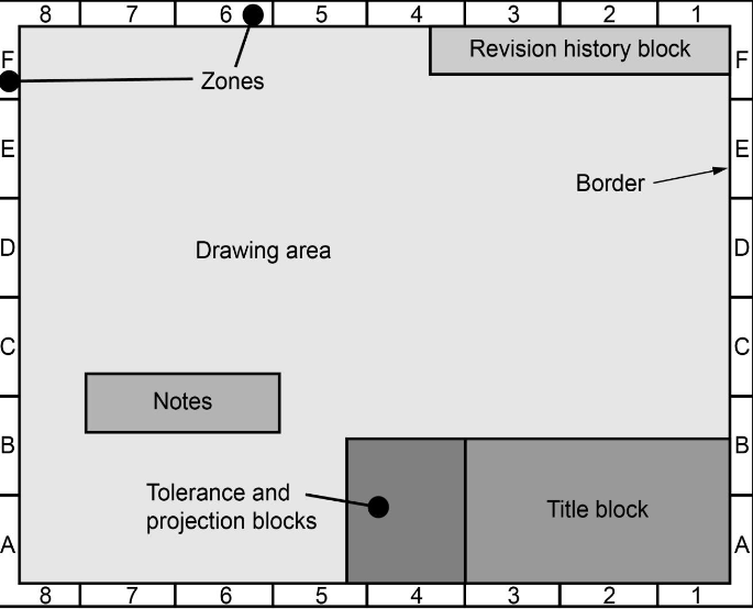
Zoning: The letter-number combinations allow you to indicate a specific location on an engineering drawing
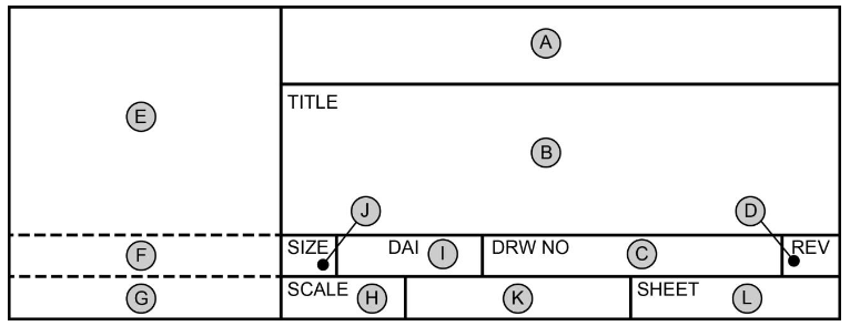
Title block
A) Company name and address
B) Drawing title
C) Drawing number
D) Sheet revision (May be omitted when revision history block is included)
E) Contains sub blocks (DRAFTER, CHECKER, & ENGINEER)
F) Approval of design when different from source preparing drawing (nescicary when contractor/subcontractor condition exists)
G) Approval for activity other than described in E & F
H) scale
I) DAI (Design activity identification
J) Drawing Size
K) Actual/Estimated weight of item
L) Sheet #
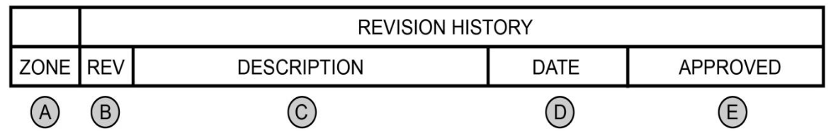
Revision history block
A) Zone location of revision
B) Revision Letter or #
C) Brief description of change
D) Revision date (year-month-day)
E) Initials of approval
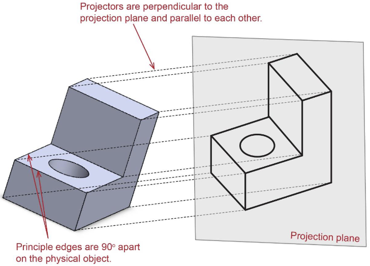
What is an orthographic projection?
An orthographic projection is a 2-D representation of a 3D object
Which one is the orthographic projection?
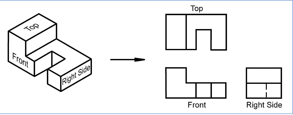
How many principal views are there?
6
Projection Lines are viewed at an _______ distance
infinate
Every object requires 6 orthographic projections to accuratley depict an object T/F?
False, the only needed projections are the ones that present new/useful information
what are the drafting standards for
- sheet formats
- Line conventions and lettering
- multiview an sectional view drawings
- dimensioning and tolorencing
1) ASME Y14.1-2005
2) ASME Y14.2M-1992
3) ASME Y14.3M-1994
4) ASME Y14.5M-1994
Key volume formulas to remember
a) extruded volume = base*height
b) Sphere (4/3)(pi)(r³)
c) Cone (1/3)(pi)(r²)(h)
d) 2(pi²)(r²)(R)
What are all the line types in orthographic projections?
Visible line
Hidden
Center
Phantom
Break
Section
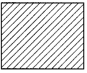
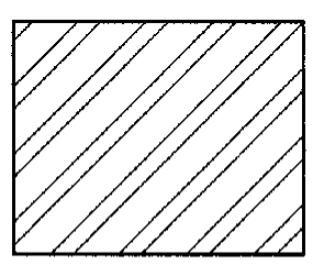
What are section lines used for?
Show cut lines and show the type of material
What are visible lines used for? ——————
represent visible edges and boundaries (0.5-0.6 mm)
What are hidden lines used for? - - - - - - - -
Reprsent edges and boundaries that cannot be seen, dashed and medium thick (0.35 - 0.45 mm)
What are center lines used for? —— — ——
Represent axes of symmetry and paths of motion, long and short dashes (about 0.3mm)
What are Phantom lines used for? —— — — ——
Used to indicate imaginary features such as 1) alternate positions of moving parts, 2) adjacent positions of related parts
lines are about 0.3mm
What are break lines used for?
show imaginary breaks in objects, made up of a series of connecting arcs ~ continuous and thick (0.5 - 0.6mm)
what are the Rules for the hidden lines?
1)length of the hidden line dashes may vary as the size of the drawing changes
2) hidden lines should always begin or end with a dash except when parallel to a visible hidden line —-| - - - -
3) dashes should join at corners
what are the Rules for the Center lines?
1) must start and end with long dashes
2) Center lines should intersect by either long or short dashes
3) lines should extend a short distance beyond the object/feature
4) can be connected within a single view to show that the features lie within the same plane
what are the Rules for the Phantom lines?
1) Phantom lines should start and end with a long dash
what are the Rules for the Break lines?
1) if the distance is short than a series of connecting arcs ~
2) if the distance is long then long thin straight line with jog is used
If two lines ocour in the same place then the less important line is omitted
cutting plane line (most important)
Visible line
Hidden line
Centerline (least)
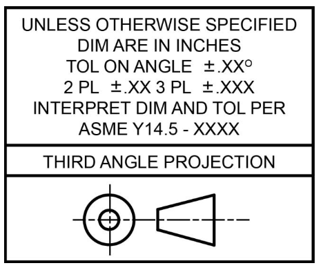
United States = 3rd angle projection
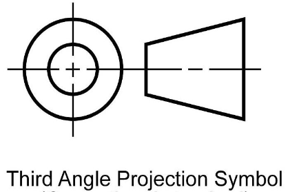
Europe = 1st angle projection
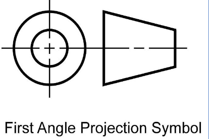
Diference between 1st and 3rd angle projections
when converting from one to another the top & bottom and left & right are switched
Tolerance and projection blocks
What are the line types used in dimensioning?
Dimension lines
Extension lines
Leader lines
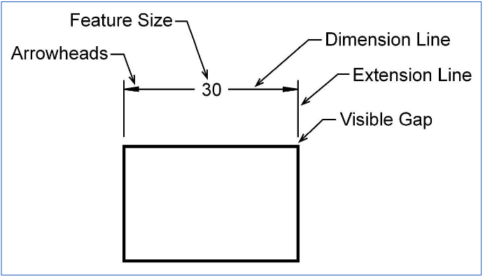
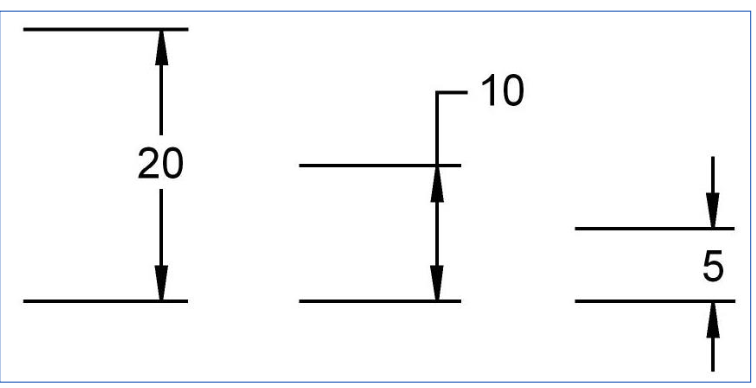
What are Dimension Lines used for?
indicates the extent of a dimension
What are Extension Lines used for?
indicates what feature is being dimensioned
What are Leader Lines used for?
adding notes on the blueprints
What are the rules for leader lines?
Crossing leaders
Long leaders
leaders that are parallel to an adjacent dimension
small angles between the leads and the terminating surface
Arrowheads
if space is limmited between the extension lines then they may be drawn outside
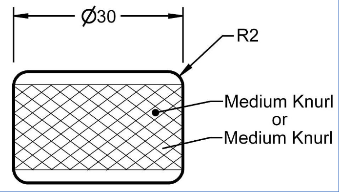
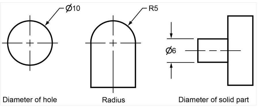
Dimensioning circulear items
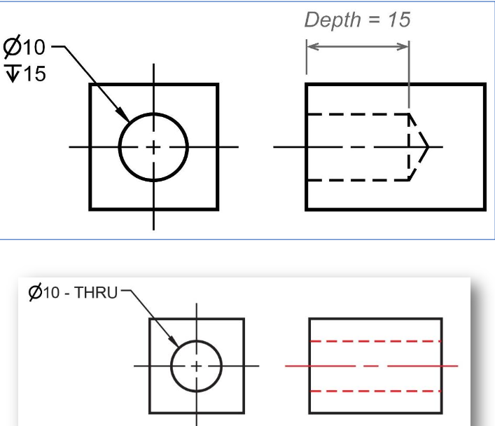
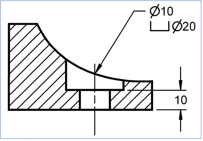
Dimensioning a blind hole
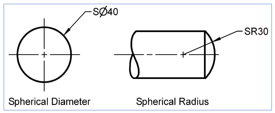
A complete sphere is dimensioned by its diameter and an incomplete sphere by its radius.
Rules for Dimensioning
1) Do not dimension inside an object unless clarity is gained
2) Dimension text should be horizontal to bottom of drawing
3) dimension text should not cover any lines or information
4) extension lines can cross other extension lines
5) dimension lines should not repeat information
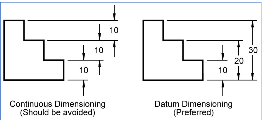
What is the prefered datum?
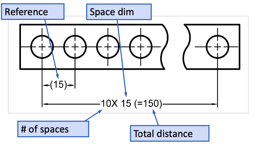
Dimensioning repetitive features
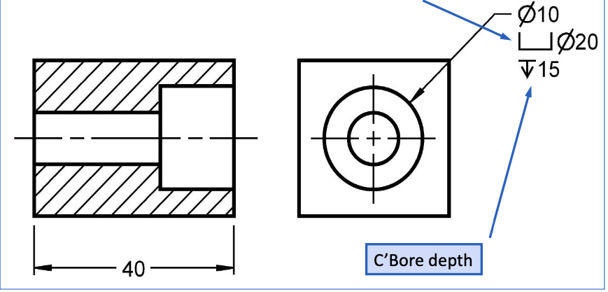
Spotfaced Hole
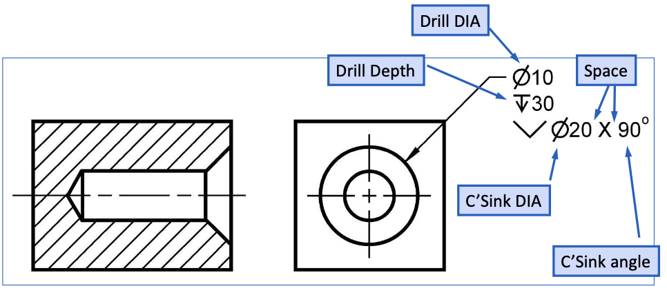
Countnter Sink hole
Counterbored Holes
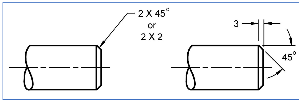
Chamfers (safety and to improve engagement of mating parts)
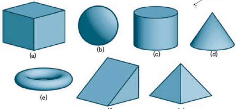
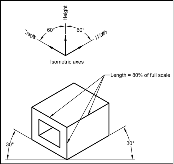
what are the pictoral types?
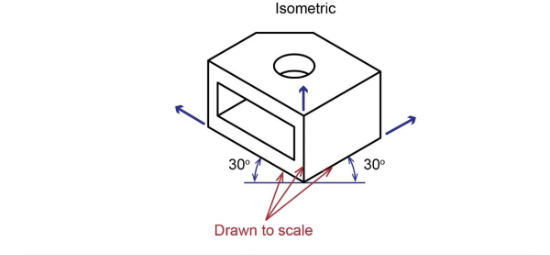
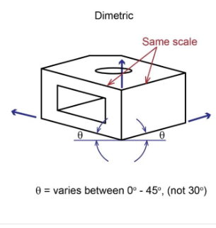
Axonometric (most common: Isometric)
Oblique (most common: Cabinet oblique)
Perspective
3 Axonometric Projections
Isometric
Dimetric
Trimetric
Axonometric - Isometric
Axonometric - Dimetric
Axonometric - Trimetric
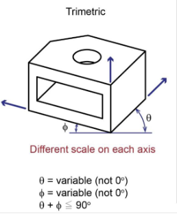
Axonometric projections have ____
projector that are perpendiculear to the projection plane and parallel to each other
Principal edges 90 degrees appart on the physical objec
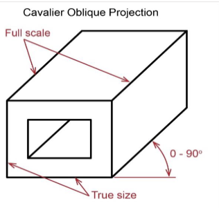
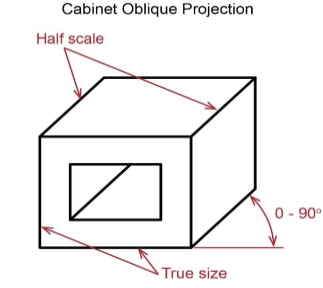
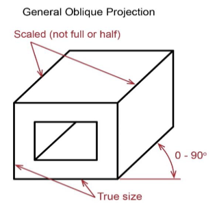
3 Oblique projections
cavalier
cabinet
general
Oblique projections are ______
not perpendiculear to the projection plane but are parallel to each other
Cavalier Oblique
Cabinet Oblique
General Oblique
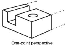
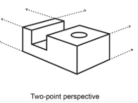
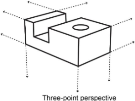
3 Perspective projections
one-point
two-point
three-point
Perspective - one-point
Perspective - two-point
Perspective - three-point
Isometric Pictoral
Sectioning
Part is cut using an imaginary cutting plane the unwanted part is mentaly discarded
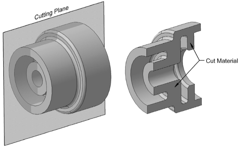
2 Cutting plane lines
Phantom (long distances)
hidden (short distances)
In section views the arrows represent ________
the portion being used
Section lines are used to indicate ___________
the cutting planes material
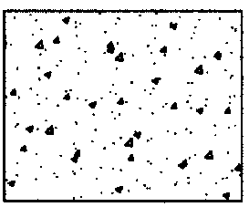
Cast Iron
Steel
Brass, Bronze, Copper
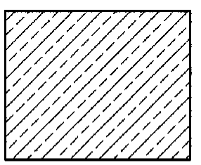
Rubber, Plastic, electrical Insulation
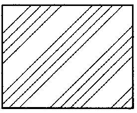
Zinc, Lead
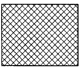
Concrete
Rules for Sectioning
1) Section line area is always bounded by a visible outline
2) Section lines in all areas are parallel (opposite lines indicate different part)
3) all the visible edges behind the cutting plane line should be shown
4)Hidden features should be omitted (except when threads or broken out sections)
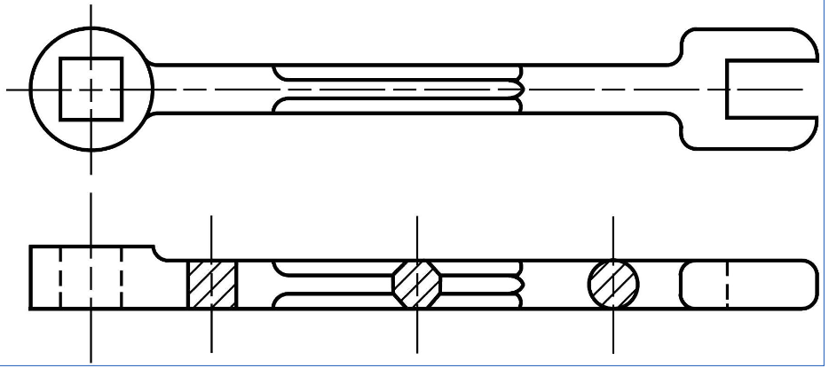
6 types of sections
Full
half
offset
broken-out
Revolved (aligned section)
Removed section (detailed section)
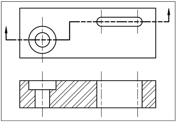
Full section
cutting plane line passes fully through object
commonly used to avoid having to dimension hidden lines
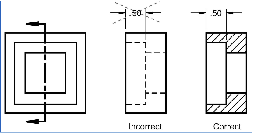
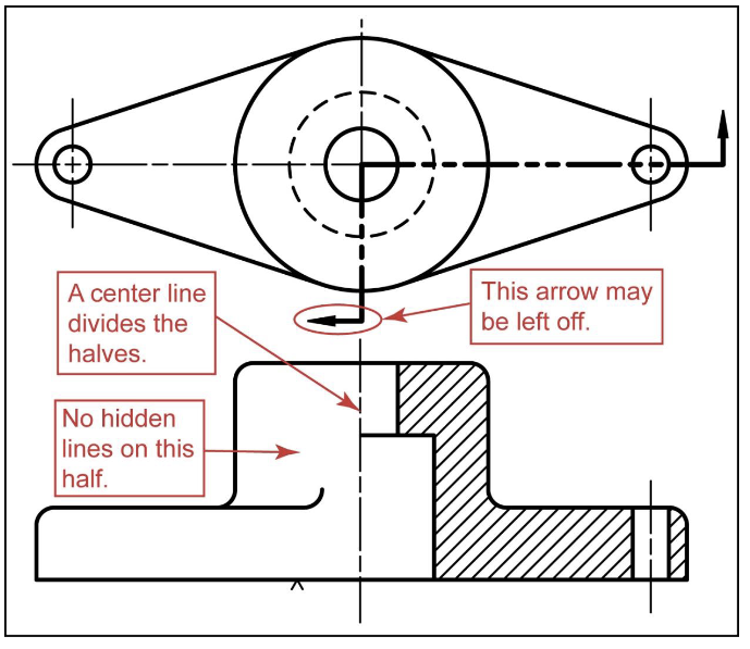
Half Section
used mainly for symetric sections
one half is sectioned
centerline is used to sepperate halves
Offset section
bending cutting plane to show features on diferent planes
Aligned section
cutting plane is bent so it passes through all features
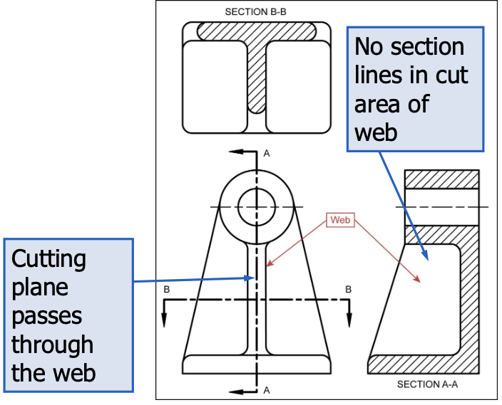
Rib and Web sections
to avoid false impression of thickness (ribs are not sectioned)
if the cutting plane passes crosswise through the rib or web we include their section lines
Broken sections
hidden lines are shown in the non-sectioned area of a broken section
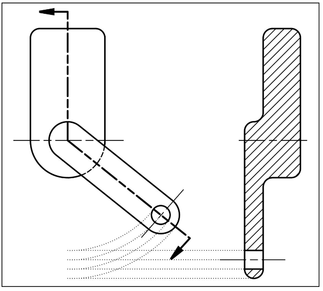
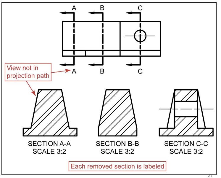
Removed section
a removed section is not in direct projection of the view containing the cutting plane
Revolved section
the cross sectional shape of an object may be shown in the longitudinal view by means of a revolved section
Non-sectioned parts
nuts
bolts
rivets
shafts
screws
for extremely thin parts less than 4mm thickness the parts should be shown __________________________
in solid black without section lines
ex:
- sheet metal
- washers
- gaskets
What are Advanced Drawings?
Are any view or part that is drawn using special rules.
What are the 4 types of advanced drawing techniques?
1) Removed and Revolved Views
2) Detailed Views
3) Partial Views
4) Auxilary Views
What do removed and revolved views look like?
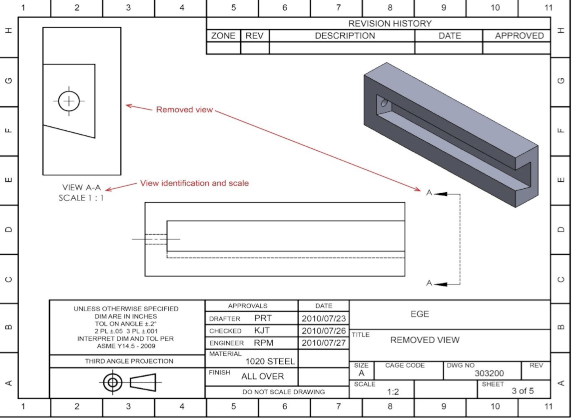
When do you use Removed and revolved views?
When Space Is limited
What do Detail Drawings Look Like ?
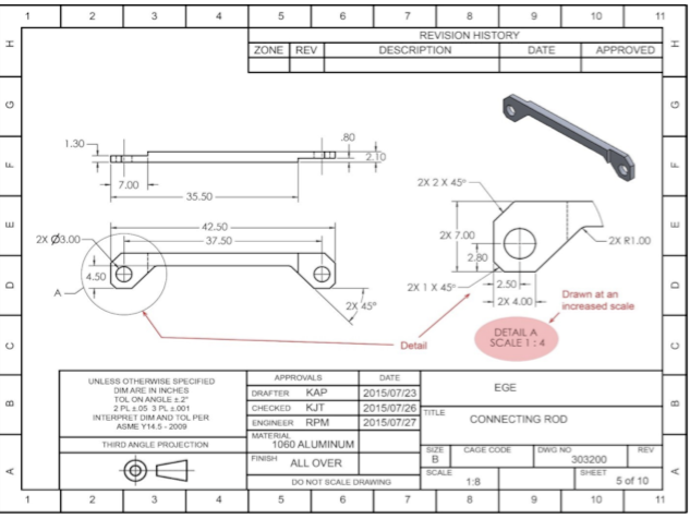
When do we use Detailed Drawings?
Used for Small Features
What do partial views look like?
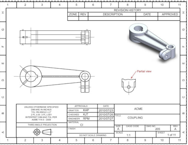
When are partial views used?
Used to show only pertinent features
What is an Auxiliary plane?
the view is created using a projection plane different from one of the six principal planes