PHYS10101 - Dynamics
1/50
There's no tags or description
Looks like no tags are added yet.
Name | Mastery | Learn | Test | Matching | Spaced | Call with Kai |
|---|
No analytics yet
Send a link to your students to track their progress
51 Terms
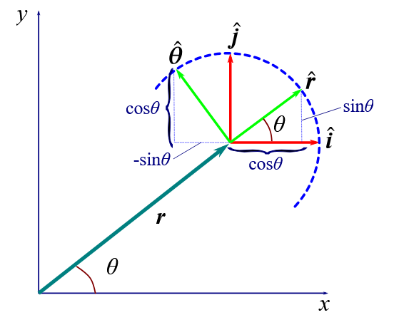
How can unit vectors of polar coordinates be written as Cartesian coordinates?
both r^ and \theta^ are functions of \theta: they change as angle changes
r^ is in the direction of r (where r =r\left(\cos\theta i+\sin\theta j\right) due to x=r\cos\theta and y=r\sin\theta)
i.e it is a vector from the centre to a point on the circumference of a unit circle. Therefore (see diagram):
r^=\cos\theta i+\sin\theta j
the direction can also simply be written as dr/dr, i.e rate of change of total vector r with respect to rate of change of magnitude of vector r
the unit vector of \theta (\theta^) must correspond to the effect that a change in angle \theta has on r, therefore
\theta^ \cdot r = \frac{dr}{d\theta}=r\left(-\sin\theta i+\cos\theta j\right)
\theta^ =-\sin\theta i+\cos\theta j
note this proves mathematically that they are always perpendicular to each other
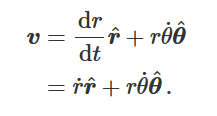
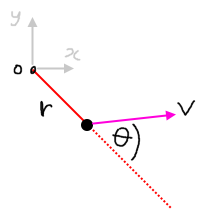
Velocity in polar coordinates
v = dr/dt, written in polar coordinates this becomes v = d/dt (rr^)
using product rule we get:
v =\frac{dr}{dt} r^ + r\frac{d}{dt}(r^)
therefore we get: (see diagram)
the first term is the radial component of velocity, the second term is the tangential component (in direction of \theta^) and can be easily found by differentiating \frac{d}{dt}(r^) and showing it is \theta^ multiplied by \frac{d\theta}{dt}
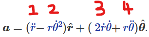
Acceleration in polar coordinates
a=\frac{dv}{dt}
(from now R will be used to represent r^ and \Theta to represent \theta^)
using equation for velocity in polar, we can write this as:
=\frac{d}{dt}\left(\frac{dr}{dt}R+r\frac{d\theta}{dt}\Theta\right)
=\frac{d^2r}{dt^2}R+\frac{dr}{dt}\frac{dR}{dt}+\left(\frac{dr}{dt}\frac{d\theta}{dt}+r\frac{d^2\theta}{dt^2}\right)\Theta+r\frac{d\theta}{dt}\frac{d\Theta}{dt}
from finding velocity we know \frac{dR}{dt}=\frac{d\theta}{dt}\Theta. by using the definition of \Theta
in a similar way to how we found this expression, we can also prove \frac{d\Theta}{dt}=-\frac{d\theta}{dt}R. Therefore, we can finally conclude: (see diagram)
in this equation, part 1 gives the linear acceleration in the radial direction (results in change in radial component of particle’s velocity), part 2 gives the centripetal acceleration directed radially inwards (note the negative!! this is VERY key for vertical circular motion questions), part 3 gives the Coriolis acceleration - a fictitious force that appears to act on a particle only if it is in motion with respect to a rotating reference frame, and part 4 gives the linear acceleration in the tangential direction (results in change in magnitude of angular velocity)
Static and dynamic friction
Static friction is the frictional force that prevents an object experiencing another force from sliding along a rough surface. It will be equal and opposite to the force trying to slide the object until the force becomes too large and the object begins to slide. The max value is called limiting static friction, Fs, and is given by Fs=\mu sN, where \mu s is the coefficient of static friction
Dynamic friction is the frictional force experienced by an object that is sliding/moving over a rough surface. It is given by Fk=\mu kN
For the same object sliding over the same surface, the coefficient of dynamic friction will be LESS than the coefficient of static friction. This means that the dynamic frictional force experienced when the object is moving can actually be less than the limiting static frictional force that has to be overcome to make the object move to begin with!
Explanation of friction: Why is it proportional to the normal reaction force, and why is the coefficient for dynamic friction less than the one for static friction?
Surfaces are never truly ‘flat’ - on a microscopic scale they are rough and bumpy.
When one surface is placed on another, the area of true contact is therefore actually very small - as little as 1/10,000th the area of the surfaces that are supposedly in contact! This means the pressure at contact points is very high leading to the contact points becoming flattened until the weight of the upper solid is supported.
at these contact points, the atoms/molecules of the two surfaces are so close together that the strong force can actually act between them, and in some cases they even become ‘cold welded’ together. These strong cohesive forces are responsible for friction.
Increasing the weight/force pushing the objects together (i.e increasing the normal reaction force!!) will increase the pressure experienced at these contact points. This means they are flattened even further and the true area of contact is increased. This means more atoms/molecules are held together by the strong force - and means that more ‘cold welding’ may take place, leading to even stronger cohesive forces = larger frictional force!
When you try to move one surface across another, you have to overcome the tiny contact points that have been ‘cold welded’ together. However, once broken, the bumps will skim over one another while one surface moves across the other and won’t ‘cold weld’ back together, hence dynamic friction is less than the limiting static friction!
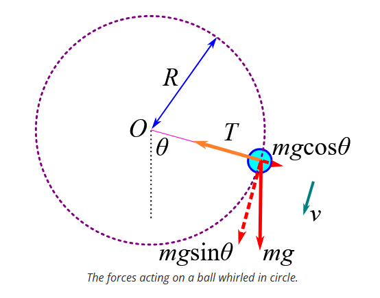
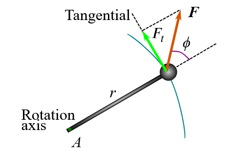
Motion in a vertical circle: Equation for tension at a given point in the circle
See diagram for visualisation of motion in a vertical circle.
We can see that here the radial components of the resultant force on the ball is given by Fr=mg\cos\theta-T
The centripetal acceleration for an object moving in circular motion is given by ar=-r\omega^2=-\frac{v^2}{r} . This can be seen from the polar coordinate equation for acceleration (see flashcard on acceleration in polar coordinates.
Newton’s second law states F=ma thereforear=\frac{\left(mg\cos\theta-T\right)}{m}=-\frac{v^2}{r}
rearranging this equation gives an expression for the tension required for circular motion at different velocities and angles of rotation:
T=m\left(\frac{v^2}{r}+g\cos\theta\right)
(note due to cos term will be max at bottom of circle when\theta=0,T=m\left(\frac{v^2}{r}+g\right) and will be min at top of circle when \theta=\pi,T=m\left(\frac{v^2}{r}-g\right))
Motion in a vertical circle: Critical velocity at highest point of particle’s motion for it to continue moving in circular motion
See diagram for visualisation of motion in a vertical circle.
recall the equation for tension/force acting radially inwards for object in vertical circular motion:
T=m\left(\frac{v^2}{r}+g\cos\theta\right)
at top of path, this radially inwards force (tension in this case) must be greater than 0, otherwise the object will no longer travel along a circular path (in this case string would go slack). Therefore, to find the critical speed, we set T = 0 and \theta=\pi (as at top of path):
0=m\left(\frac{v^2}{r}-g\right)
v=\sqrt{rg}

Work: calculating work done from non-constant force
W=\int_{x0}^{x1}\!F\,dx
i.e, work done by a spring pushing a horizontal block (on smooth surface) from x0 to x1 gives:
W=\int_{x0}^{x1}kxdx
W=\frac12k\left(x1-x0\right)^2 , if x1 = x, x0 = 0, gives
W=\frac12kx^2 - Elastic potential energy!! (as W = total energy)
Work: Calculating work with vectors (3D space etc)
W=\int_{r0}^{r1}F\cdot dr , where F is a vector force and is a function of (vector) r.
Therefore, as a\cdot b=\left|a\Vert b\right|\cos\theta,
W=\int_{r0}^{r1}F\left(r\right)\cos\left(\theta\right)dr , note here that F is a scalar and will give scalar answers when r1 and r0 are subbed in
This is called a line intergral.
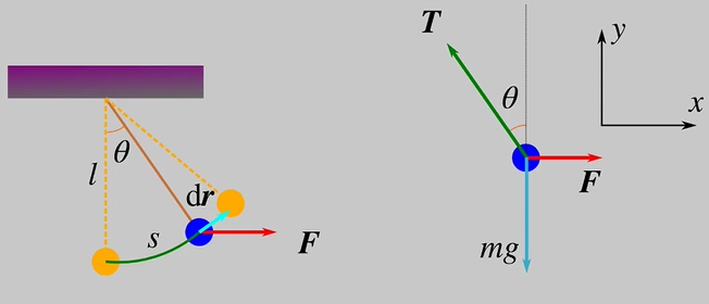
Work: Simple pendulum example
See diagram for sketch of pendulum and free body diagram
We can see that F=T\sin\theta and mg=T\cos\theta, therefore F=mg\tan\theta, giving us an expression of F as a function of theta.
From the line integral for work, we know that W=\int_{r0}^{r1}F\left(r\right)\cos\theta dr. This is in terms of r, so we want to find in terms of theta. Therefore, we need expressions linking r to theta and dr to d(theta):
r to theta: From diagram we can see r is unchanging. Therefore, at r0, we can just say \theta0=0 and at r1, \theta1=\theta (where theta is the final angle reached)
dr to d(theta): From diagram we can also see s=l\theta (simple circle stuff in radians!). We can also see that dr = extra s added on, meaning
dr=ld\theta
So, W=\int_{r0}^{r1}F\cos\theta dr=\int_0^{\theta}Fl\cos\theta d\theta
W=\int_0^{\theta}mg\tan\theta\cos\theta ld\theta=mgl\int_0^{\theta}\sin\theta d\theta
W=mgl\left(1-\cos\theta\right)
Work: The Work-Energy Theorem
States that the work done by a resultant force on a particle = the change in kinetic energy of the particle
When resultant force is constant, a = constant so this can easily be proved with SUVAT, W = Fx, and F = ma. When F is not constant in magnitude but is constant in direction, we can use the simple W=\int_{x0}^{x1}F\left(x\right)dx and F=ma=mv\frac{dv}{dx} to get W=\frac12m\left(v1^2-v0^2\right), but when F is not constant in both direction and magnitude, things are a bit more complicated:
General case: (called general case as also works for previous 2 cases)
F=m\frac{dv}{dt} where both F and v are vectors.
We must use line intergral W=\int_{r0}^{r1}F\cdot dr with this which gives:
W=\int_{r0}^{r1}m\frac{dv}{dt}\cdot dr=\int_{t0}^{t1}m\frac{dv}{dt}\cdot vdt
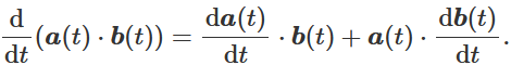
Integration by “looking at it” (reverse product rule in this case!) shows us:
\frac{dv}{dt}\cdot v=\frac12\frac{d\left(v^2\right)}{dt} (see diagram for definition of product rule. What happens if a(t) = b(t) = v ?). Note that v is no longer a vector here (dot product has been used!)
Therefore:
W=\int_{t0}^{t1}\frac12m\frac{d\left(v^2\right)}{dt}dt=\int_{\frac12mv0^2}^{\frac12mv1^2}d\left(\frac12mv^2\right)=\frac12m\left(v1^2-v0^2\right)
Work: What is power?
Power is the total work done over total time taken, i.e work done per unit time:
P=\frac{dW}{dt} ,W=\int_{r0}^{r1}F\cdot dr , so P=\int_{v0}^{v1}F\cdot dv (F is vector function of r/v)
When v is constant, P=F\cdot v
CoM: Finding centre of mass of a rigid body
We consider the rigid body as a system of closely packed particles: We divide it into n small elements, each with mass \Delta mi, located at points ri=\left(xi,yi,zi\right)
The coordinates of the centre of mass for the x coordinate is given by:
\left(\sum_{i=1}^{n}\Delta mi\right)xcm=\sum_{i=1}^{n}\Delta mixi (and same for y and z coordinates)
If we increase n, the number of elements, to infinity, \Delta mi will tend to 0, therefore (for x as example but same for each coordinate):
xcm=\lim_{\Delta mi\to0}\frac{\sum_{i=1}^{n}\Delta mixi}{\sum_{i=1}^{n}\Delta mi}=\frac{\int xdm}{\int dm}=\frac{1}{M}\int xdm
Therefore equivalent vector equation is:
rcm=\frac{1}{M}\int rdm (r as vector)
This centre of mass is useful as we can use it as the point that all external forces act
CoM: Mass per unit length and it’s uses
Mass per unit length is.. the mass of an object.. per, it’s.. unit length
depicted with symbol \lambda where for uniform objects, \lambda=\frac{M}{L} (L is total length) and for non-uniform objects, \lambda will equal some function of r (or x if 1D rod), usually over L (as mass varies with x position along L so M/L becomes f(x)/L). This will be given in question (hopefully)
It is useful as it allows us to rewrite the rigid body equation, rcm=\frac{1}{M}\int rdm (or it’s version for individual coordinates, i.e x), as an integral of dr:
\int dm=\int_0^{L}\lambda\left(x\right)dx when working with rods with length along x axis (note when uniform, lambda(x) will simply equal lambda, as it is not a function of x as mass per unit length is same at all points of x)
therefore xcm=\frac{1}{M}\int xdm becomes xcm=\frac{1}{M}\int_0^{L}x\lambda\left(x\right)dx
CoM: Proof that all external forces can be thought of acting on the centre of mass
We know Mrcm=m1r1+m2r2+\cdots . Differentiating this gives us M\frac{d}{dt}rcm=m1\frac{d}{dt}r1+m2\frac{d}{dt}r2+\cdots=Mvcm=m1v1+m2v2+\cdots
Differentiating again will give us:
Macm=m1a1+m2a2+\cdots+mnan . Using F = ma, we see:
Macm=F1+F2+\cdots Fn
i.e, the total mass of the system * by the acceleration of system at CoM is equal to the vector sum of all the forces acting on the group of particles
Among these forces, some will be internal forces, i,e if system is system of planets and stars, gravity, or if system is a solid rock, intermolecular forces between the atoms of the rock. N3 shows us these internal forces occur in equal and opposite pairs, so cancel each out.
Therefore,
Macm=\sum_{i=1}^{n}Fi=Fext , where Fext is the vector sum of external forces acting on the system, and can be thought as all acting at the CoM.
CoM: The kinetic energy of a system of particles - theorem and proof
Theorem:
“The kinetic energy of a system of particles equals the kinetic energy associated with the motion of the centre of mass PLUS the kinetic energy associated with the motion of the particles relative to the centre of mass”
K=Kcm+Krel
Kcm=\frac12Mvcm^2
Krel=\sum_{i}\frac12miui^2 (where ui is velocity of ith particle relative to CoM)
Proof:
KE of system = sum of KE of individual particles, i.e K=\sum_{i}\frac12mivi^2
As ui is the velocity of ith particle relative to CoM velocity, vi can be written as vi=vcm+ui
Therefore:
K=\frac12\sum_{i}\operatorname{mi}\left(vcm+ui\right)^2=\frac12vcm^2\sum_{i}\operatorname{mi}+vcm\cdot\sum_{i}\operatorname{mi}ui+\frac12\sum_{i}\operatorname{mi}ui^2
As Mvcm=\sum_{i}mivi and vi=vcm+ui, \sum^{i}miui must equal 0 (to keep definition of vcm true)
Therefore:
KK=\frac12Mvcm^2+\frac12\sum_{i}\operatorname{mi}ui^2
CoM: The reduced mass
For two particles,
vcm=\frac{m1v1+m2v2}{m1+m2}
vrel=v1-v2
Rearranging gives expressions for v1 and v2:
v1=vcm+\frac{m2}{M}vrel
v2=vcm-\frac{m1}{M}vrel
Expressing Kinetic energy (\frac12m1v1^2+\frac12m2v2^2) in terms of vcm and vrel using these equations gives:
K=\frac12Mvcm^2+\frac12\mu vrel^2
where mu is the reduced mass and is given by:
\mu=\frac{m1m2}{m1+m2}
Reduced mass describes the relative motion of two particles. This is useful for looking at forces that only depends on separation (i.e electron “orbiting” proton, Earth orbiting Sun), as the associated Ek is the relative kinetic energy, governed by the reduced mass.
If one mass is significantly larger than the other, i.e m1 « m2, we find that \mu\approx m1, so the reduced mass approximately equals the smaller of the two masses (i.e in electron-hydrogen example, the reduced mass would be almost the mass of the electron)
Energy: Using Work-Energy principle to find work done by other forces (than wd by potential energies)
If other forces than gravity and elastic forces do work on a body,
Wtotal=Wgrav+Wel+Wother
Total work done = change in kinetic energy (Work-Energy theorem):
Wgrav+Wel+Wother=\Delta K=K2-K1
Wgrav/Wel is equal to the change in their respective potential energies, so:
\left(Gpe1-Gpe2\right)+\left(Epe1-Epe2\right)+Wother=K2-K1
rearranging gives:
Wother=\left(K2+Gpe2+Epe2\right)-\left(K1+Gpe1+Epe1\right)
Wother=\left(K2+U2\right)-\left(K1+U1\right)
Wother= Final total energy - Initial total energy
Wd by all other forces than gravitational and elastic ones equals the change in total mechanical energy of the system
Energy: Conservative and non-conservative forces
Conservative forces are forces which produce a reversible energy change, i.e force does work to change the configuration of the system and then does work to put the system back to how it was originally, if the force is conservative then the energy of the system should be identical before and after the “round trip” occured - total work done is zero.
Properties:
1) Work done by a conservative force is reversible
2) Work done on moving round a closed path under influence of conservative force is zero
3) Work done by a conservative force is independent of path, depending only on starting and ending points (i.e GPE is only dependent on height between two points, not the path the object takes between two points)
Both GPE and elastic potential energy are conservative forces. i.e when ball is dropped from height h, GPE converts to Ek. Assuming at surface it bounces perfectly elastically, it will reach height h again and all Ek will have been converted back into GPE - total work is zero.
Non-conservative forces do not do work that is reversible, i.e friction and air resistance: Imagine mass connected to horizontal spring oscillating along a smooth surface - Elastic force is conservative so total energy is NOT changed (energy just converted between Epe and Ek) and the total work done from moving the mass from max compression to max extension and back again (one “round trip”) is zero. Now imagine surface is rough - No matter how the mass is moving (i.e away or towards spring), friction always opposes motion so does negative work, meaning energy is “lost” to friction - total work done is not zero after a round trip.
Non-conservative forces are also not independent of path taken: Imagine two points, A and B on a rough surface. Work done by friction when moving a mass from A to B will be different depending on path taken - will be minimal if mass takes a perfectly straight path from A to B, but will be larger if mass takes a longer (curved) path.
Remembering that total work done on an object equals the total change in mechanical (kinetic) energy, we can therefore write:
Wtotal=Wcons+Wnoncons=\Delta Ek
Note that this is just another way of saying work done by forces other than Gpe/Epe and Ek equals the change in mechanical energy, as when you have Gpe/Epe and Ek as a pair, the energy loss from one equals the energy gain from the other so work done by conservative forces equals 0
Energy: Force and potential in 3D
Imagine you have a conservative force where F = (Fx, Fy, Fz). As force is conservative:
\Delta U=-\int_{r0}^{r}F\cdot dr
This can also be written as:
F\left(r\right)=-i\frac{\partial U}{\partial x}-j\frac{\partial U}{\partial y}-k\frac{\partial U}{\partial z}
Energy: Going from a potential energy function to a force - what does this show us about conservative forces?
We’ve seen going from a force function to a potential energy as \Delta U=-\int_{x0}^{x}F\left(x\right)dx. What about if we want to find F from U(x)?
Consider 1 dimension: we know for conservative forces, W=-\Delta U . This can be written as, for a small displacement \Delta x (so that F(x) is reasonably constant over the interval),
W=F\left(x\right)\Delta x=-\Delta U
F\left(x\right)=-\frac{\Delta U}{\Delta x}As change tends to zero,
F\left(x\right)=-\frac{dU}{dx}
Simple derivative (duh)
However, this is still somewhat relevant - the negative shows us that A conservative force always acts to push the system towards lower potential energy: If F(x) is in same direction as displacement (x), U(x) decreases. If F(x) is in the opposite direction to displacement, potential energy increases with increasing x
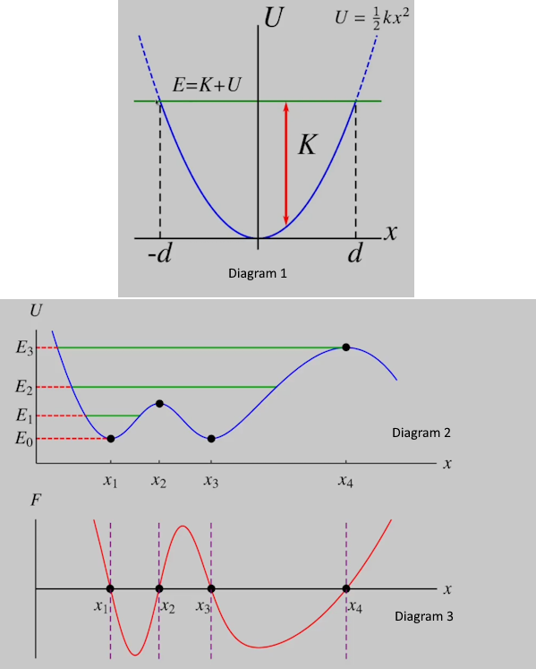
Energy: Potential energy diagrams
Graphs of potential energy as a function of position (x). Can be used to visualise details about the dynamics of a system.
i.e, in diagram 1, the potential energy diagram for a mass on a spring that can oscillate between max extensions of d to -d, we see the total energy of the system (will equal U at d or -d, as at this point all energy is potential energy). Knowing that total energy = U + Ek, and plotting a line at the total energy, gives us an easy way to visualise the kinetic energy of the system at a given x value (equal to difference between E and U)
Diagram 2 shows an example of a potential energy diagram with multiple stable and unstable equilibrium positions. Stable equilibria (at x1 and x3) are points where derivative is 0 - force will always return to these points. Unstable equilibria (at x2 and x4) are points where the derivative is 0 but the force will always push away from, i.e if an object was at x2 or x4, it would move away back towards either x1 or x3 (whichever was closer). At energy = E0, the object would be in stable equilibrium and would not move. At E1, the object would move towards x1 as it is the only reachable stable equilibria (i.e x3 here is NOT stable as to get there it would have to first increase potential energy above the total energy! = not doable). At E2, both stable equilibria are reachable - object oscillates between them! E3 is the max energy the system can have and still oscillate - if energy was higher, the object would “move away to infinity” and escape the “potential well”. Diagram 3 shows the plot of force against position for this potential energy diagram, showing why this would be the case.
Momentum: Linear momentum of a system of particles
Imagine system of n particles of masses mi. Assume no mass enters or leaves so that M=\sum_{i=1}^{n}\operatorname{mi}
Total momentum will be P=m1v1+m2v2+\cdots+m_{n}v_{n}
We know from CoM stuff that v_{\operatorname{cm}}=\frac{m1v1+m2v2+\cdots+m_{n}v_{n}}{M}
therefore we can see that:
P=Mv_{\operatorname{cm}}
Differentiating this also shows us the idea that all external forces could be thought of acting through the CoM, i.e
\frac{d}{dt}P=Ma_{\operatorname{cm}}=F_{ext}
Momentum: Conservation of momentum
If no external forces act on a system, momentum is conserved.
Note momentum is a vector so if no external forces act in x direction (for example) but there are external forces acting in y and z direction, momentum in x direction is conserved, but momentum is not conserved in the other directions - this is key in glancing collisions (where there will be both an x and y component for final velocities)
This can obviously be seen by F = ma = d/dt(P) - if no forces act, then d/dt(P) = 0, momentum is not changing!
Momentum is conserved in collisions as no external forces act - forces exerted on each object by the other object as they collide make equal and opposite pairs within the system.
Momentum: Impulse
Defined as time integral of force:
I=\int_{ti}^{tf}Fdt , i.e
I=\Delta P , Impulse is change in momentum of a collision
Momentum: Coefficient of restitution and (in)elastic collisions
Coefficient of restitution Is a measure of the elasticity of a collision - in perfectly elastic collisions (e = 1), Ek is conserved, but it is not in all other collisions. e = 0 gives a perfectly inelastic collision - objects stick together and move with a common velocity (i.e m1v1i+m2v2i=\left(m1+m2\right)vf). e of any other value between 0 and 1 gives a partially inelastic collision - Ek is not conserved and particles do not move together after the collision (v1f does not equal v2f)
equation given by:
e=\frac{\left|vf2-vf1\right|}{\left|vi2-vi1\right|} , i.e separation speed over approach speed. (easier to think logically than try and do equation)
Circular motion: Angular motion parameters (and equations linking them to linear ones)
d\theta = angular displacement (\theta is angular position, see polar coords)
\omega=\frac{d\theta}{dt} = angular velocity (note this is a vector quantity, i.e could be rotation around x, y, or z axis)
\alpha=\frac{d\omega}{dt} = angular acceleration (again vector quantity)
If angular velocity and angular acceleration have same sign (in same direction), rotation speeding up. if opposite sign, rotation slowing down
SUVAT can be done with these angular parameters just like it can be done for linear ones.
conversions:
v=r\omega
a_{r}=r\omega^2=\frac{v^2}{r} - centripetal acceleration, i.e acceleration radially inwards towards centre of circular motion (causes turning effect)
a_{t}=r\alpha - tangential acceleration, i.e acceleration tangent to radius of circular motion
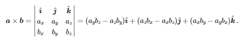
Circular motion: Vector product
Written as a × b
Gives a vector that’s direction is perpendicular to the two vectors used in calculation
The magnitude of the vector is given by \left|c\right|=\left|a\Vert b\right|\sin\theta (theta is angle between vector a and b)
Can be calculated by hand using a 3×3 matrix with unit vectors in first row, values of ax, ay, and az in second row, and values of bx, by, and bz in third row. The determinant of this matrix gives the vector product, c (see diagram) Note: remember alternating signs.
Circular motion: Moment of inertia (definition)
Moment of inertia is the “rotational equivalent of mass” - basically it tells you how hard it is to rotate something, just like mass tells you how hard it is to move something (due to momentum)
I=mr^2 (or I=\sum_{i=1}m_{i}r_{i_{}}^2 for a collection of particles / rigid body)
Units are kg m²
Circular motion: Moment of inertia (derivation)
We can derive it from the kinetic energy of a particle moving in circular motion:
particle of velocity v and mass m that is moving in circle of radius r has kinetic energy given by
Ek=\frac12mv^2
This can be written in terms of angular velocity as
Ek=\frac12mr^2\omega^2
We then define moment of inertia = I=mr^2 (or I=\sum_{i=1}m_{i}r_{i_{}}^2 for a collection of particles / rigid body)
Therefore Ek can also be written as
Ek=\frac12I\omega^2, showing us how it is the rotational equivalent of mass mathematically (replaces m when we replace v with it’s rotational equivalent)
It’s units are kgm²hh
Circular motion: Moment of inertia of rigid bodies
For rigid bodies, we saw that the moment of inertia of the body is calculated from I=\sum_{i=1}m_{i}r_{i_{}}^2. This shows that it depends on the distribution of the mass of the object about the axis, i.e if all the mass is distributed further from the axis (r is on average larger) than an object of identical mass but different distribution (r is on average less), the first object has a larger moment of inertia despite having the same mass.
This can best be shown by comparing the moment of inertia of a hoop and disc of equal mass (see diagram) For the hoop, all of it’s mass is approx. R from the rotation axis, whereas the disc mass is distributed evenly between r = 0 and r = R, meaning ri in the expression for moment of inertia of the disc will be substantially less than that of the hoop - hoop has larger moment of inertia.
Circular motion: Moments of inertia for various key shapes
Rod:
about centre:I=\frac{1}{12}ML^2
about end: I=\frac13ML^2
L is length of rod. Assuming rod as 2D (i.e has no radius - see cylinder section for “rods” with radius, a.k.a cylinders)
Cylinder/disc:
About symmetry axis (i.e through centre of flat face): I=\frac12MR^2
KEY POINT!!! Remember that flywheels are often cylinders!!! hence they have moment of inertia equal to this!
About diameter (i.e parallel to flat face, through centre of cylinder): I=\frac14MR^2+\frac{1}{12}ML^2
L is length of cylinder (does NOT equal 2R!!!!!!). Note how the second part of this equation is the inertia about centre of rod, as this is basically just a rod with radius now. Also note how a disc will have L = 0. In this case, inertia about symmetry = 2* inertia about diameter, much like that of a hoop (see below)
Hoop:
About symmetry axis: I=MR^2 (as hoops assume all mass located R away from centre)
KEY POINT!!! Remember that pulleys are often hoops (= thin cylindrical shells)!!! hence they have moment of inertia equal to this!
About diameter: I=\frac12MR^2
note about symmetry axis = 2* about diameter
Spheres:
SOLID sphere: I=\frac25MR^2
HOLLOW sphere: I=\frac23MR^2
Circular motion: Kinetic energy expressed in terms of rotational parameters and why this is useful (solving circular motion questions with energy conservation).
Ek=\frac12I\omega^2
This is really useful for problems to do with rotating flywheels etc, or objects like rods that are connected to a pivot and “fall” from a horizontal to vertical position. Conservation of energy still holds, so E = Ek + Ep. This Ek can be written in angular form to find kinetic energy of rotating objects much easier.
Example:
Light cable is wound around a flywheel of mass M and radius R. A block of mass m is connected to the other end of the cable and is released a distance h above the floor. (see diagram). As it falls, the cable does not slip. (hence speed, v, of both the flywheel’s motion and block’s motion is equal)
We can use conservation of energy to find the speed of the block AND angular velocity of flywheel once the block hits the ground:
Initially, Ek = 0 and Ep = mgh
Finally, Ek = Ek of mass + Ek of flywheel (remember it’s TOTAL Ek of combined system) and Ep = 0
Hence,
mgh=\frac12mv^2+\frac12I\omega^2
As flywheel is just glorified cylinder, I=\frac12MR^2. Remember that the speed that both objects move at will be equal (as cable does not slip) so omega can also be written in terms of v using \omega=\frac{v}{R} (as rope does not slip over flywheel - if it did we couldn’t use this)
mgh=\frac12mv^2+\frac12\left(\frac12MR^2\frac{v^2}{R^2}\right)=v^2\left(\frac12m+\frac14M\right)
This allows us to find v, the speed of the block when it hits ground. We can then use the conversion \omega=\frac{v}{R} to find the rotational velocity of the flywheel.
Circular motion: Torque (definition)
Torque is the analouge for force in rotational motion, and is defined by a vector product:
\tau=r\times F , where F is force acting on a point and r is the distance between that point and the axis of rotation.
Note how this is similar to the definition of a moment, but is NOT a moment! Moment does not have to cause rotation and is just a normal force, whereas torque is specifically a rotational force (which can be caused by a moment).
Circular motion: How is torque and inertia linked? (Using torque and N2 to link torque and inertia)
Imagine a particle of mass m on a massless rod of length r, where the other end is pivoted about an axis perpendicular to the rod. A force F acts to the particle (as shown in diagram)
N2 shows us that Ft=ma_{t} (subscript t denotes tangential direciton, i.e perpendicular to rod)
The torque is \tau=Ftr=ma_{t}r
We know that a_{t}=r\alpha, so \tau=mr^2\alpha
Note that for this system (1 particle), I=mr^2 , hence \tau=I\alpha !!
This also applies for rigid bodies: Consider a rigid body of lots of particles rotating about a fixed axis. Each particle has the same angular velocity, so same angular acceleration. This means we can write:
\tau_{net,i}=m_{i}r_{i}^2\alpha , where the net subscript identifies the torque as the net force on the particle
For all particles in the body, the sum of all their net torques is equal to the net external torque acting on the system (much like net force acting on a system is equal to net external force, as seen with Newton’s laws). Therefore, we can write:
\sum_{i}\tau_{net,i}=\sum_{i}m_{i}r_{i}^2\alpha=\tau_{ext}
Remember that for rigid bodies, I=\sum_{i=1}m_{i}r_{i_{}}^2. This means that this also simplifies to:
\tau_{ext}=I\alpha !!
Circular motion: Finding angular acceleration of pulleys when a force is acting on them.
Remember definition for Torque:
\tau_{}=F\times R=F_{\tan}R=I\alpha
Imagine a pulley of radius R and mass M which is a thin cylindrical shell (i.e hoop so I=MR^2)
A rope runs over the pulley. Before the pulley, the tension is T1, after it is T2. This means a force of F = T2 - T1 acts to rotate the pulley.
This force will be acting perpendicular to the pulley at a distance of R (as force acts parallel to rope, and as rope wraps around circumference of pulley, rope will always be perpendicular to the pulley)
Hence, \tau=FR=\left(T2-T1\right)R and \tau_{}=MR^2\alpha
Setting these equal allows us to find angular acceleration of the pulley!
note that above equation is only true for pulleys that are thin cylindrical shells. For example, if instead the question states the pulley is a cylindrical disc (i.e full cylinder), inertia will instead equal I=\frac12MR^2, and etc for other shapes.
Circular motion: torque on a rigid body due to gravity
See diagram. The torque on an individual particle of mass mi due to gravity is mig * xi , where xi is the lever arm of the force
Therefore, net gravitational torque on a body is given by:
\tau_{g}=\sum_{i}m_{i}x_{i}g
Remember that \sum_{i}m_{i}x_{i}=Mx_{\operatorname{cm}} !! Therefore, we can see that the net gravitational torque on a body is simply calculated by considering the entire weight of the body acting through the centre of mass!
\tau_{g}=Mx_{\operatorname{cm}}g
Circular motion: Moment of inertia in integral form
I=\sum_{i}m_{i}r_{i}^2 (sum form)
This can be rewritten as an integral with respect to change in mass:
I=\int r^2dm
This is useful for finding moment of inertia of continuous rigid bodies, by considering the object is made up of lots of small elements of mass dm
Circular motion: Deriving moment of inertia for a cylinder (disc) rotating round it’s symmetry axis (axis perpendicular to it’s plane face)
Recall integral form of moment of inertia: I=\int r^2dm
a cylinder of mass m, radius R, length z (which we need even though it will cancel out later) has dm=\rho dV
density can be written as total mass * total volume=\frac{M}{\pi R^2z} (assuming is constant density as r changes)
dV can be expressed as dAdr, aka the integral of dV: \int_{o}^{R}2\pi rzdr
So, I=\int_{o}^{R}r^2dm can be rewritten as:
I=\frac{M}{\pi R^2z}\int_{o}^{R}r^2\cdot2\pi rzdr
I=\frac{M2\pi z}{\pi R^2z}\int_0^{R}r^3dr
I=\frac{2M}{R^2}\left(\frac14R^4\right)=\frac12MR^2 , which is the equation for moment of inertia of a disc!
(this is harder for rings - it involves \Delta R terms (for ring, outer radius is R, inner radius is R-\Delta R), which when put to a power are ignored as it is assumed that the ring is very thin so \Delta R is very small. Rest of steps are same but just remember to set powers of \Delta R equal to 0)
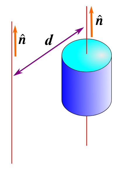
Circular motion: The parallel axis theorem (definition)
States that the moment of inertia about an axis through the centre of mass of an object is related to the moment of inertia about another parallel axis by the equation:
I=I_{\operatorname{cm}}+Md^2
where M is the total mass of the object and d is the distance between the parallel axes (distance between axis through CoM that produces inertia Icm to the axis parallel to it that produces inertia I)
Circular motion: The parallel axis theorem (derivation/proof)
Recall parallel axis theorem, moment of inertia through centre of mass is linked to the moment of inertia through a parallel axis distance d away by the equation. I_{d}=I_{\operatorname{cm}}+Md^2. This is what we want to prove.
Proof uses vector product
define ri as the position of each particle (of the object) relative to the centre of mass of the object.
Remember that \sum_{i}m_{i}r_{i} gives the position of the centre of mass. As we have defined ri as relative to the centre of mass, this will actually equal zero!
\sum_{i}m_{i}r_{i}=0
Let the direction of both rotation axis (one through CoM and one parallel to it) be unit vector n. Assume the axes are a perpendicular distance d from each other (i.e n and d are perpendicular, see diagram)
We now define ri’ as the position of each particle relative to a point on the new rotation axis, i.e ri’ = ri + d (again, see diagram - imagine +ve direction of d runs from new axis to axis through CoM and matches +ve direction of ri).
ri’ may not be perpendicular to the direction vector n (because ri might not have been either). To ensure that when calculating the inertia around this axis the distance we use is perpendicular, we use the vector product, as shown. The moment of inertia around the new rotation axis will therefore be given by:
I_{d}=\sum_{i}m_{i}\left(n\times r_{i}^{\prime}\right)^2
I_{d}=\sum_{i}m_{i}\left(n\times\left(r_{i}+d\right)\right)^2
This can be expanded like a usual quadratic:
I_{d}=\sum_{i}m_{i}\left(n\times r_{i}^{}\right)^2+2\sum_{i}m_{i}\left(n\times r_{i}\right)\cdot\left(n\times d\right)+\sum_{i}m_{i}\left(n\times d\right)^2
first term: Note here that \sum_{i}m_{i}\left(n\times r_{i}^{}\right)^2 is the moment of inertia around the centre of mass, I_{\operatorname{cm}}, as \left(n\times r_{i}\right) gives the distance of the point ri that is perpendicular to n.
last term: Note here that as n and d are defined as being perpendicular, n X d = d, so this term becomes \sum_{i}m_{i}d^2. This simply equals Md^2!
middle term: 2\sum_{i}m_{i}\left(n\times r_{i}\right)\cdot n\times d can be rewritten as \left(n\times2\sum_{i}m_{i}r_{i}\right)\cdot\left(n\times d\right).
Note from before that \sum_{i}m_{i}r_{i}=0, meaning this term simplifies to \left(n\times0\right)\cdot\left(n\times d\right)=0
Therefore, the expression can be simplified to:
I_{d}=I_{\operatorname{cm}}+0+Md^2
I_{d}=I_{\operatorname{cm}}+Md^2
Circular motion: Expressing work done in terms of Torque
Consider a force, F, acting to rotate an object through an angle of d\theta.
The point of application of the force would move a distance of s=rd\theta, so in terms of normal force, the change in work done would be given by:
dW=F\cdot ds=F_{\tan}rd\theta
(note how in first equation, F is vector, whereas Ftan is the magnitude of the F vector that is perpendicular to distance rd\theta)
Remember definition of torque: \tau=F\times r as a vector, meaning the magnitude is given by \tau=F_{\tan}r. We have this in our equation!! Therefore:
dW=\tau d\theta , so work done during a finite (angular) displacement given by:
W=\int_{\theta1}^{\theta2}\tau d\theta=\tau\theta_{total}
note how this is literally analogous to the translational equation W=\int_{x1}^{x2}Fdx; we have just replaced the translational factors with their rotational counterparts (force for torque, displacement for angular displacement)
Circular motion: Expressing power in terms of Torque
Remember that in angular terms, the work done is given by dW=\tau d\theta (W=\tau\theta_{total}).
Remember that power is simply rate of work done, i.e P=\frac{dW}{d\theta}. Therefore power is simply:
P=\tau\frac{d\theta}{dt}=\tau\omega
note how, yet again, this is just analogous to the translational equation for power, P = Fv
Circular motion: Work-energy theorem for rotational movement
Recall that kinetic energy for a rotating object can be expressed as Ek=\frac12I\omega^2
Remember the work-energy theorem (for translational motion) states that the work done by a force on a body is equal to the change in kinetic energy of that body. In rotational motion, torque is analogous to force, so for a rotational body:
“work done by a torque on a body is (also) equal to it’s increase in kinetic energy”
W=\Delta Ek=\frac12I\left(\omega_2^2-\omega_1^2\right)
Circular motion: What is the non-slipping condition and what does it mean? (rolling without slipping)
The non-slip condition states that for an object rotating along a path without slipping, v_{\operatorname{cm}}=r\omega (vcm = v if particle or object that acts like particle, like a uniform density ball)
If something (i.e a wheel) is rolling without slipping along a surface, a point on the circumference of the object would have moved S metres (in a circular path) when the object itself has moved S metes along the path (see diagram).
This means:
S=r\theta=vt , where r is the radius of the object and v is it’s translational velocity (i.e Vcm)
From this we can differentiate and then differentiate again to find the equations:
v=r\omega
a=r\alpha
which allow us to link rotational movement to translational movement. Note that these equations can only be used in situations where object is rolling without slipping.
Circular motion: Angular momentum
2 ways of writing:
Way 1:
“Normal” momentum defined as p = mv. Angular momentum is defined as:
L=r\times p
L=m\left(r\times v\right)=mrv_{}\sin\theta ,
where theta is angle between direction of v and direction of r (often extended to make it clearer, see diagram)
Note that like torque, angular momentum is also defined in reference to a specific point, in the diagram for example, L=mrv_{}\sin\theta defines it in reference to the origin.
Way 2:
Like the rate of change of linear momentum is equal to the net force acting on the object, the rate of change of angular momentum is equal to the net torque acting on it:
\frac{dL}{dt}=\tau (or \frac{dL_{sys}}{dt}=\tau_{ext} if a rigid body)
Torque can be written as \tau=I\alpha, therefore angular momentum can also be written as
L=I\omega
This can be seen below:
\frac{dL}{dt}=m\frac{d}{dt}\left(r\times v\right)=m\left(\frac{dr}{dt}\times v+r\times\frac{dv}{dt}\right) (using product rule)
\frac{dL}{dt}=m\left(v\times v+r\times a\right)=m\left(0+r\times a\right)=r\times ma
r\times ma=r\times F=\tau , therefore
\frac{dL}{dt}=\tau
Circular motion: Conservation of angular momentum
“If no external torques act on a system, angular momentum is conserved” (analogous to linear momentum being conserved if no external forces)
Ice skater example:
Ice skater rotating on (frictionless) ice around the axis of symmetry (axis through CoM). Only forces acting on them are weight and normal reaction force, which both go through CoM, so no external torques acting on the skater.
Angular momentum therefore must be conserved. Angular momentum can be written as L=I\omega. By bringing in their arms, skater reduces moment of inertia, I, so rotational speed, omega, must increase and they rotate faster.
Circular motion: Rolling WITH slipping
When slipping, the non-slip condition v_{\operatorname{cm}}=r\omega no longer applies (means cannot use a=r\alpha either)
vcm will be greater than romega, but as it slides (assuming no other forces acting on ball), kinetic friction opposing it’s linear motion will decrease the value of vcm, and also increase the value of omega (as induces a torque on the ball, see diagram) until the non-slip condition is satisfied again and the ball rolls without slipping.
Example:
Solid ball of mass m and radius R is thrown so instant it touches the floor it is moving horizontally with speed v0 and is NOT rotating. coefficient of kinetic friction =\mu_{k}.
Find time ball slides for, distance it slides, and the speed when it begins to roll without slipping.
linear: F=\mu_{k}mg=-ma , a=-\mu_{k}g ,
v=v_{o}-\left(\mu_{k}g\right)t
x=v_{o}t-\frac12\left(\mu_{k}g\right)t^2
angular: \tau=\mu_{k}mgR=I\alpha , I=\frac25mR^2 (solid sphere),
\alpha=\frac52\frac{\mu_{k}g}{R}
\omega=\omega_{o}+\frac52\frac{\mu_{k}g}{R}t (note omegao is 0 as stated in Q)
Ball stops slipping when v_{\operatorname{}}=R\omega holds:
v_{o}-\mu_{k}gt=\frac52\mu_{k}gt , t=\frac27\frac{v_{o}}{\mu_{k}g}
Subbing this into distance equation gives:
x=\frac{12}{49}\frac{v_{o}^2}{\mu_{k}g}
Subbing into v_{\operatorname{}}=R\omega using equation for omega gives velocity at that point:
v=\frac52\mu_{k}g\cdot\frac27\frac{v_{o}}{\mu_{k}g}=\frac57v_{o}
This is now the uniform speed at which the ball will travel at (when rolling without slipping on flat surface, point of ball in contact with surface is at rest relative to surface = no friction force / torque!)
Gravity: Kepler’s 3rd law
T^2=\frac{4\pi^2}{GM}r^3
Gravity: Spherical shells of mass (finding equation of Fg relative to r)
imagine sphere of mass M and radius r. Imagine sphere has mass density \rho\left(r\right). How does the gravitational force that this sphere change with it’s radius?
Now imagine we add a spherical shell around the sphere of width = dr. As we have added a shell, M has changed!!! hence there has been a change in the force (dF).
We can express this by imagining a mass m which is a distance of R from the centre of the sphere. We can now write an equation for dF:
dF=\frac{-GmdM}{R^2}
Note that we can write dM=\rho dA=\rho Adr , which in this case is dM=4\pi r^2\rho\left(r\right)dr. Note how we have used r here, as we want area of sphere, and it being multiplied by dr will make it account for both sphere and shell (aka make it dA, see equation)
Now we have the final equation: (for when R > r, remember that R < r, F will just = 0)
dF=\frac{-Gm4\pi r^2\rho\left(r\right)}{R^2}dr
Assuming we are given an equation for the density function, we can now integrate from r = 0 to r = R to find the total force, F.
Gravity: Gravitation inside Earth (assuming constant density)
As you travel inside the Earth, you’d expect two things to happen to the gravitational force:
1) It would increase as r decreases
2) it would decrease as M (below you) decreases
For constant density, the decrease dominates as M\left(r\right)=\frac{\rho4}{3}\pi r^3dr and the gravitational force would be given by F=-\frac{GM\left(r\right)m}{r^2}
this gives us:
F=-Gm\rho\frac43\pi r ,
which assuming constant density means \rho=\frac{Me}{\frac43\pi\operatorname{Re}^3} (Me and Re are mass and radius of normal Earth respectively) can also be written as
F=-\frac{GmMe}{\operatorname{Re}}r , F decreases linearly as r decreases.