CSA M1S2
1/52
There's no tags or description
Looks like no tags are added yet.
Name | Mastery | Learn | Test | Matching | Spaced | Call with Kai |
|---|
No analytics yet
Send a link to your students to track their progress
53 Terms
data section
bss section
text section
3 sections of an assembly program
data section
declaring initialized data or constants
section .datasection .datasyntax for declaring data section
bss section
section used for declaring variables
section .bss section .bsssyntax for declaring bss section
text section
section that is used for keeping the actual code
begins with declaration
global _startglobal _startkernel where the program execution begins
section .text
	global _start
_start:
syntax for declaring text section
;
comment for assembly language
executable instructions
assembler directives or pseudo-ops
macros
3 types of statements in assembly language
executable instructions
tell the processor what to do
contains an operation code
generates one ML instruction
assembler directives or pseudo-ops
tell the assembler about the various aspects of the assembly process
non executable and do not generate ml instructionsma
macros
text substitution mechanism
![<p>[label] mnemonic [operands] [;comment]</p>](https://knowt-user-attachments.s3.amazonaws.com/e0548d04-0529-410f-bbf7-e8eacc9263de.jpeg)
[label] mnemonic [operands] [;comment]
format of assembly language statements
mnemonic - name of instruction
operands - parameters of the command
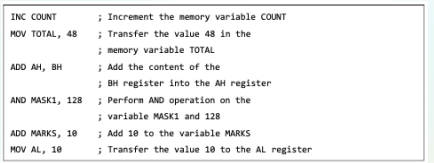
nasm -f elf hello.asmcode to assemble the program in nasm
ld -m elf_i386 -o hello hello.ocode to link the object file and create an executable file
./hellocode to execute the program
segmented memory model
divides the system memory into groups of independent segments referenced by pointers located in the segment registers
data segment
code segment
stack
3 assembly memory segments
data segment
.data and .bss
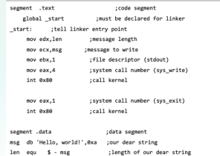
.data - declare the memory region, where data elements are stored for the program
.bss - static memory section that contains buffers for data to be declared later in the program. zero-filled buffer memory
code segment
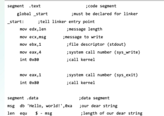
.text
defines an area in memory that stores the instruction codes
fixed area
stack
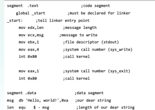
contains data values passed to functions and procedures within the program
registers
store data elements for processing without having to access the memory
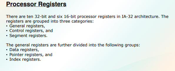
data registers
4 32-bit data registers are used for arithmetic, logical, and other operations
As complete 32-bit data registers: EAX, EBX, ECX, EDX.
Lower halves of the 32-bit registers can be used as four 16-bit data registers: AX, BX, CX and DX.
Lower and higher halves of the abovementioned four 16-bit registers can be used as eight 8-bit data registers: AH, AL, BH, BL, CH, CL, DH, and DL.
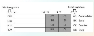
AX - primary accumulator
used in input/output and most arithmetic instructions
primary accumulator
AX
BX - base register
used in indexed addressing
base register
BX
CX - count register
store the loop count in iterative opreations
DX - data register
also used in i/o operations. also used with AX for multiply and divide operations
pointer registers
32-bit EIP, ESP, and EBP registers and corresponding 16-bit right portions IP, SP, and BP
3 categories":
instruction pointer
stack pointer
base pointer
instruction pointer IP
16bit register
stores the offset address of the next instruction to be executed
in association with the CS register, gives the complete address of the current instruction in the code segment
stack pointer SP
16bit register
provides the offset value within the program stack
associated with SS register, refers to be current position of data or address within the program stack
base pointer BP
16 bit register
helps in referencing the parameter variables passed to a subroutine
address in SS register is combined with the offset of this register to get the location of the parameter
also can be combined with DI and SI as base register for special addressing

source index
destination index
2 sets of index pointers
index registers
ESI and EDI, and their 16-bit rightmost portions, SI and DI, are used for indexed addressing and sometimes used in addition and subtraction.
source index
used as source index for string operations
destination index
destination index for string operations
control registers
32 bit instruction pointer register and 32 bit flags register combined to get this
many instructions involve comparisons and mathematical calculations and change the status of the flags and some other conditional instructions test the value of these status flags to take the control flow to other location
overflow flag OF
indicates the overflow of high-order bit (leftmost bit) of data after a signed arithmetic operation
direction flag DF
determines left or right direction for moving or comparing string data
DF set to 0 = string operation takes LtoR direction
DF set to 1 = string operation takes R to L direction
interrupt flag IF
determines whether the external interrupts like keyboard entry, are to be ignored or processed
IF set to 0 = disable interrupt
IF set to 1 = enable interrupt
sign flag SF
shows the sign of the result of an arithmetic operation
set according to the sign of data item following the arithmetic opreation
positive result = clears the value of SF to 0
negative result = sets the value of SF to 1
zero flag ZF
indicates the result of an arithmetic or comparison operation
nonzero result = clears zero flag to 0
zero result = sets to 1
auxiliary carry flag AF
contains the carry from bit 3 to bit 4 following an arithmetic opreation; used for specialized arithmetic
AF set when 1byte arithmetic opreation causes a carry from bit 3 to bit 4
parity flag PF
indicates the total number of 1bits in the result obtained from an airhtmetic opreation
an even number of 1 bits clears the parity flag to 0 and an odd numbre of 1 bits stes the parity flag to 1
carry flag CF
contains the carry of 0 or 1 from a high order bit (leftmost) after an airthmetic opreation
stores the contents of last bit of a shift or rotate opreation

segments
specific areas defined in a program for containing data, code, and stack
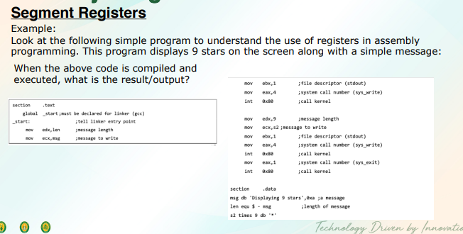
code segment
data segment
stack segment
3 main segments
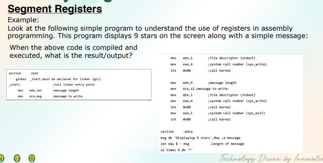
code segments
contains all the instructions to be executed
data segment
contains data, constants and work aras
stack segment
contains data and return addresses of procedures or subroutines. it is implemented as a ‘stack’ data structure