Computed and digital radiography
1/84
There's no tags or description
Looks like no tags are added yet.
Name | Mastery | Learn | Test | Matching | Spaced | Call with Kai |
|---|
No study sessions yet.
85 Terms
What is the centre point for this radiograph? - patient is in right lateral recumbency for a medio-lateral view of the stifle joint
The stifle joint

What are the collimation borders for this radiograph? - patient is in right lateral recumbency for a medio-lateral view of the stifle joint
Cranial and caudal skin edges, mid-shaft femur and mid-shaft tibia and fibula

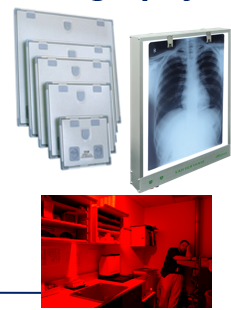
Film-Based conventional radiography
One of the oldest methods of developing a radiograph and still used today
Uses conventional x-ray film (similar to photographic film - sensitive to white light - visible light)
Enclosed in a light proof container known as a rigid cassette
Film must be handled in a ‘safe-lighting’ until after the processing stage → dark room
Film put through a possessor containing chemicals to develop the radiograph
The primary components of film-based conventional radiography include the ..
X-ray cassette
Intensifying screens
Radiographic film and film processing

Film-based radiography - the film is sensitive to ..
White light and must be stored in the cassette until processing

Chemicals to develop the radiograph include ..
Developer and fixer followed by the wash stage

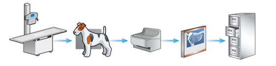
The stages of film-based conventional radiography
X-ray machine and table
Patient positioned on cassette (containing a film) and exposure is made
Film removed from cassette and put through a processor containing chemicals (in dark room)
X-ray film assessed on an x-ray viewer (light source)
X-ray film stored in filing cabinets
Editing of the final film is not possible when using film-based conventional radiography, why is this?
Physical radiography is produced can be held
Major disadvantage is using this method in contrast to computed and digital radiography
Why is film-based conventional radiography rarely used today?
Time consuming
Requires a new film for every exposure - expensive and environmental considerations
Involves the use of hazardous and irritant chemicals during processing - developer and fixer
Inability to manipulate the image - as not a digital form
Multiple exposures often requires to produce a diagnostic x-ray
Film faults commonly occur
Filing cabinets and floor space required to store x-rays
Film-Based Conventional Radiography - Time consuming
Longer processing times resulting in prolonged anaesthesia or sedation for the patient as it often takes between 2-5 minutes to process the radiograph depending on the processor
Additional delays caused if multiple exposures are required - due to incorrect settings resulting in a non-diagnostic radiograph
Maintaining the automatic process with film-based conventional radiography is also time consuming, e.g. checking chemical levels, machine temp checks, weekly cleaning routines
Film-Based Conventional Radiography - Multiple exposures often required to produce a diagnostic x-ray
Often due to the incorrect settings being used within film-based conventional radiography
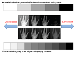
Due to the narrow exposure latitude of film-based conventional radiography (in contrast to the wide exposure latitude of computed and digital radiography) too many or too little x-ray photons reaching the x-ray film will result in a non-diagnostic or compromised image meaning repeat radiographs are required
Film-based conventional radiography has a narrow latitude (shorter grey scale) than computed settings can produce an image that is either too white/light or too black/dark
Film-Based Conventional Radiography - Film faults
Mostly due to incorrect settings, processing and poor maintenance of equipment
Film-Based Conventional Radiography - Filing cabinets and floor space required to store x-rays
Many practices using film-based conventional radiography store radiographs for approximately 5 years
Storage space and filing cabinets are required which can be difficult in smaller practices
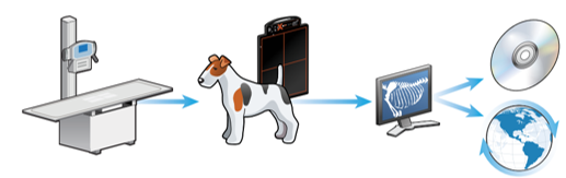
Digital Radiography
A generic term used to describe the images that are created and stored electronically and viewed on a computer
Digital radiography is split into two categories ..
Computed radiography (CR)
Direct digital radiography (DDR) and indirect digital radiography (IDR)
With both systems of digital radiography they have ..
The same health and safety considerations apply as ionising radiation is used - Ionising Radiations Regulation 2017
A radiographer/RVN/VS is still required to position the patient accurately and select appropriate exposure factors
The acquired image is created, viewed and stored on a computer
A hard copy may be printed and/or disseminated
Computed radiography - cheaper option as the practice just needed to buy their cassette and imaging plate
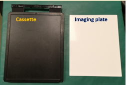
Replaces conventional film with an imagine plate (IP) → reusable and may be used in conjunction with a conventional x-ray machine
IPs contained within cassettes look very similar to conventional cassettes. Designed to protect plate from handling and light

Layers of an Imaging Plate - Computed Radiography
Protective layer
Phosphor layer
Light-reflective layer
Conductive layer
Support layer
Light-shielding layer
Backing layer
Barcode label

The protective layer of an Imaging plate
Top layer that protects the phosphor layer (very think but tough plastic)
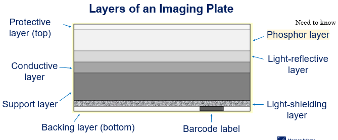
The phosphor layer of an imaging plate
Traps electrons during an exposure (an important layer) Plays an important part in imaging production itself

The light-reflective layer of an Imaging plate
Send light in a forward direction when released in cassette reader/processor

Conductive layer of an Imaging plate
Absorb and reduces static electricity helping to prevent artefacts on the radiograph

Support layer of an imaging plate
A rigid layer giving the Imaging plate strength

Light-shielding layer of an imaging plate
Protects Imagine plate and prevents light from erasing image

Backing layer of the imaging plate
Bottom layer and another protection layer

Barcode label of the imaging plate
Links to Imaging plate with patient examination
How does computed radiography work?
Patient details entered onto computer system along with selected examination
Imaging plate from a photostimulable phosphor
During an exposures, the imaging plate traps x-rays and stores them as energy in the phosphor layer to produce a latent image on the plate
Cassette is placed into processor (must be within a few hours of the exposure)
Once in the processor, the imaging plate is automatically extracted
Imaging plate by a helium neon laser which releases the stored electrons, emitting photons of light
Light is detected, amplified and converted into an image in approximately one minute
Imagine then appears on the computer screen for assessment and/or manipulation - possessing take approx. 60-120 seconds
Latent
Existing but not yet developed/visible (requires further development) - image has been produced
Cassette containing Imagine Plate must be processed within a few hours. Why?
The trapped electrons will return to a lower energy state if left for prolonged periods
This can have an effect on the imagine quality (fading)
This can be considered a disadvantage of using computed radiography, especially when performing field work as the Imaging plate may not be processed until hours after making the exposure
We are unable to see what go on within the processor. The processor removes the need for a dark room because ..
It is light-proof and automatically processes the Imaging plate. Additionally, there are no chemicals involved in the processing stage
In computed radiography, once the image has been transferred onto the computer screen, the IP is automatically cleaned by a high-intensity bright white light source. Then ..
The IP is then replaced in the cassette and ejected from the processor
Can be re-used immediately for subsequent x-rays
Image may be stored on computer or disc and can be printed

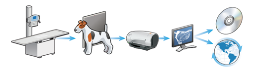
Stages of computed radiography
X-ray machine and table
Patient positioned on cassette, containing IP and exposure is made
Cassette containing IP inserted into computed radiography processor and x-ray converted to a digital image
Image assessed on a computer screen (may be manipulated)
Image digitally stored and may be disseminated
Stage one of computed radiography
The x-ray table and machine could be an older system (one used in film-based conventional radiography) as long as a computed radiography imaging processor is used to develop the radiograph

Stage three of computed radiography
No chemicals are used during the processing stage and handling of the Imagine plate occurs within the processor so there is no need for a dark room when using this radiography system
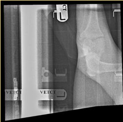
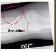
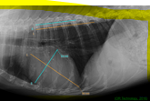
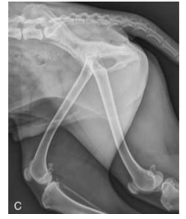
Computed radiography - What has occurred in this image to make it non-diagnostic?
Two images are seen in the image which are the Cranial caudal stifle joint, and the Medial lateral stifle joint

Computed radiography - Why might this image be non-diagnostic?
The cassette didn’t clear before taking the second x-ray
Equipment maintenance for computed radiography
Regular checks of both the Imaging pate and cassette to assess for damage (cracks and scratches)
Store Imaging plate within the cassette at all time
Store cassette upright
Use imaging plate cleaner (from manufacturer) rather than water
Erase imaging plate prior to use on a daily basis - sensitive to scatter
Why should the imaging plate be stored within the cassette at all times?
To protect it from dirt, damage and moisture
Why should the cassette be stored upright?
To reduce build up of dust and friction damage
Prevent the horizontal compression, and not within the radiography room
Why must water not be used to clean the imagine plate?
Water can be absorbed into the phosphor layer, causing damage and poor image quality
When using the recommended imaging plate cleaner, what should be used to clean it?
Soft lint free material should be used to prevent fibres from sicking to the imaging plate and scratches, e.g. cotton wool

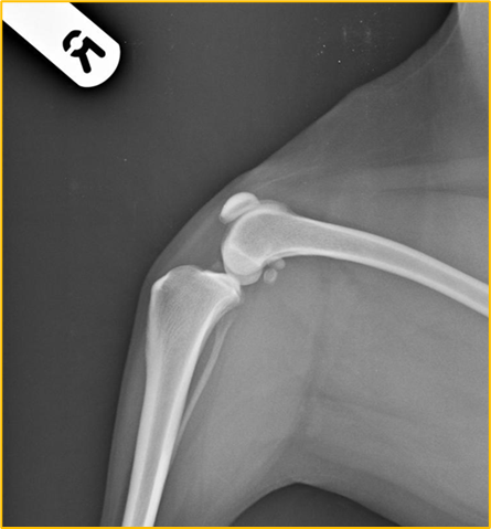
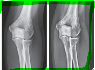
What does this radiograph show?
Cranio-caudal stifle joint

What is the centre point of this radiograph?
Stifle joint

What are the collimation borders for this radiograph?
Distal femur, proximal tibia and fibula, lateral skin edges

Is there anything missing on this radiograph (radiograph created using a computed radiography system) ?
Right/left marker
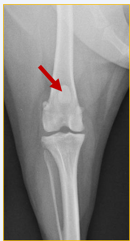
What anatomical structure is the red arrow pointing to?
Patella
Direct and indirect digital radiography
Uses technology to proved an almost immediate on-screen image within a manual processing stage
X-ray detectors → rigid flat panel detectors (FPDs) or changed coupled devices (CCDs) connected to a computer (wired or wireless) (rather than using Imaging plate and cassettes in computed radiography)
How does direct digital radiography work?
One-phase process → x-ray photons directly converted into an electrical charge. No visible light intermediary stage
How does indirect digital radiography work?
Two-phase process → x-ray photons converted into visible light, then conversion of visible light into an electrical charge
Both Direct and indirect digital radiography convert x-ray energy into ..
An electrical signal
Direct and indirect digital radiography requires ..
Dedicated x-ray generating equipment and cannot be used with conventional equipment - expensive to purchase

The stages of direct and indirect digital radiography
X-ray machine and table (whole unit/package)
Patient petitioned of FPD and exposure is made → DDR - One phase process, IDR - Two phase process
Image assessed on a computer screen (may be manipulated)
Image digitally stored and may be disseminated
Stage two of direct digital radiography
One-phase process
FPDs used to convert x-ray energy directly into digitised electrical energy

Stage two of indirect digital radiography
Two phase process
FPDs contain intensifying screen to covert x-ray to light
Light is then converted into an electrical charge
Advantages of digital radiography systems (CR, DDR and IDR)
Reduced repeat exposure rates due to wide latitude/dynamic range - have more grey scare to play with
Ability to view different structures on the same radiograph - tissues with a wide range of attenuation e.g. bone and soft tissue
Quicker processing time and no chemicals
Less storage space required as image stored electronically
Fewer processing faults
Ability to manipulate images posy processing
Ability to disseminate radiographs - teleradiology
Cost-effective
Computed and digital radiography have a wide exposure latitude, this allows ..
A larger range of exposures resulting in the production of a diagnostic image
This often reduces the need for repat exposure
This additionally saves time and money and reduces radiation exposure to both the patient and staff
computed and digital radiography has the ability to view different structures on the same image
Tissues with a wide range of attenuation may be viewed on the same image, for example bone, soft tissue, thicker and tinner areas of the patient.
Attenuation
Absorption and scatter of the x-ray beam as it passes through the patient
Computed and digital radiography have quicker processing times in contrast to conventional film-based radiography. This decreases the ..
Anaesthetic/sedation time for the patient and enables a quicker throughout x-ray cases each day
Computed and digital radiography take up less storage space, this is because
Images are stored electronically so there is no need for filing cabinets
There are fewer processing faults in CR and DR because ..
As there are no chemicals involved in CR and DR, there are no filming handling faults when using these methods
Film faults and artefacts are still possible when using digital systems but are less common
The majority of faults that occur with CR and Dr are ..
Patient positioning faults, for example, rotation, movement blur, etc..
The initial cost of CR and DR systems are high, but in the long-term they are cost-effective, this is because ..
No processing chemicals required, no conventional film required, quicker processing time = less anaesthetise and electricity use, no postage fees as electronically stotted

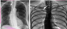
Advantage of CR and DR in regards to exposure - Yellow
The yellow circle indicates overexposure - this radiograph was created using film-based conventional radiography
The x-ray setting for the pelvis and lumber spine is ok but too high for the hindlimbs
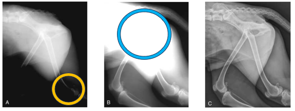
Advantage of CR and DR in regards to exposure - Blue
Blue circle indicates underexposure
This radiograph was used using a film-based convention radiography
X-ray settings for the stifles/lower hindlimbs is ok, but not high enough for the pelvis and lumber spine
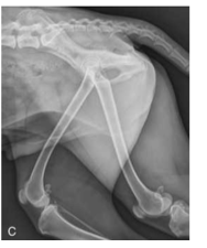
Advantage of CR and DR in regards to exposure
Perfect image quality
Importance of post-processing techniques
Valuable in enhancing the image and improving diagnostic value
Post-processing techniques
Magnification
Cropping
Rotation
Brightness and contrast enhancement
Subtraction
Edge enhancement
Annotation
Mirroring
Measurements
Post-processing cropping involves
The removal of unwanted areas/borders of the radiograph.
Should only be centering and collimating on the area of interest so cropping shouldn’t be done often
Structures of variable tissue thickness can be viewed on the same radiograph by using the brightness and contrast enhancement tool. This is not possible when using film-based conventional radiography as the radiograph is printed and cannot be edited (also due to the narrow exposure latitude).
The image can be manipulated after processing using this tool to alter the brightness and contrast which enables differences in tissue thickness to be examined on the same radiograph à for example, you can often examine soft tissue and bone without having to take separate images.
Post-processing Subtraction involves
The removal of superimposed or unnecessary structures from the image which improves the prominence of anatomical area of interest
Post-processing edge enhancement helps to
Improve the visibility/sharpness of small high-contrast areas, e.g. foreign bodies in soft tissue
Post-processing annotation is a useful tool as the Veterinary Surgeon is able to make short notes on the radiograph including measurements and labelling.
This method should not be abused by using it instead of correctly placing the manual right/left marker as it is bad practice to label digital radiographs using the annotation tool
Post-processing mirroring is a useful tool as multiple radiographs can be viewed simultaneously on the same screen as opposed to having multiple radiographs to view when using film-based conventional radiography
This tool is often used when comparing/contrasting radiographs, e.g. left and right limbs, before and after sugary etc ..
Post-processing measurements may need to be taken, for example, to measure the size/length of a fracture.
This technique will assist the veterinary surgeon in selecting the correct sized orthopaedic plates, wires, and pins etc .. required for the fracture repair procedure
Direct and indirect digital radiography advantages
Faster processing (almost instant)
Higher quality images and finer resolution (compared to CR) - less conversion of the image
Ability to view the image immediately on screen
May be more hygienic = less cleaning
Why does DDR and IDR have finer image resolution?
Digital radiography involves less conversion of the image during processing
How is DDR and IDR more hygienic?
There is less equipment meaning there is less to clean in comparison to film-based conventional radiography, CR and DR where a separate FPD is used
Disadvantages of CR and DR
Initial cost of purchasing and installation of CR and DR systems high
Exposure creep
Potential for over interpretation of images - often due to magnification tool
Tendency for laziness and poor collimation
Limitation in dental radiography
New and unfamiliar equipment
A major disadvantage of using digital radiography systems is exposure creep
As digital radiography systems have a wider exposure latitude, high exposure factors are not easily recognised as they would be if using film-based conventional radiography - which would be evident through a low contrast, blacker image due to the film being overexposed)
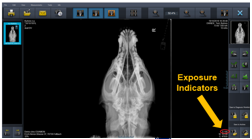
To overcome the unnecessary exposure to radiation, most digital systems now include exposure indicators - also know as exposure index
Exposure indicators have a numerical value associated with each image which is aimed at indicating how suitable the exposure is. For an appropriate exposure ..
This number should sit within a given range of valves provided by the manufacturer
The manufacturer of the system provides a chart with the expected value range for different examinations.
This enables staff to evaluate the amount of radiation used per exposure to help determine whether the settings were too high or too low and also to ensure the dose the patient is receiving is as low as reason achievable (ALARA) while still guaranteeing a quality radiograph
An over or underexposed image will deliver an incorrect exposure indicator whereas a correct exposure will provide a corresponding exposure indicator. Although exposure indicators are useful, there are still problems associated with their use including the following ..
Staff may ignore the exposure indicators (unlike when using film-based conventional radiograph staff with be able to see when a film is overexposed
Staff must understand how to use exposure indicators and have access to the manufactures value range
No standard value range - different for each manufacturer system
Tendency for laziness and poor collimation – Collimation and cropping may be corrected/performed once the image is on screen and because of this staff may not centre and collimate the primary beam correctly when positioning the patient. This has two major implications…
The patient is being exposed to excessive and unnecessary levels of radiation - as correct and collimation has not been performed. This is also a health and safety implications
More scatter radiation is provided which degrades the image quality - also a health and safety implication. The effect of scatter radiation on the image includes blackening, blurring and a reduction in contrast and definition
Digital radiography include multiple digital systems
Computed radiography
Direct digital radiography
Indirect digital radiography