topic 2 - electricity
1/108
Earn XP
Description and Tags
Name | Mastery | Learn | Test | Matching | Spaced |
|---|
No study sessions yet.
109 Terms
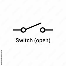
state the symbol for an open switch
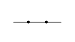
state the symbol for a closed switch
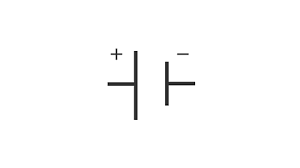
state the symbol for a cell
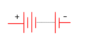
state the symbol for a battery
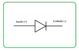
state the symbol for a diode
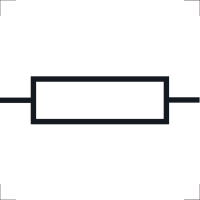
state the symbol for a resistor
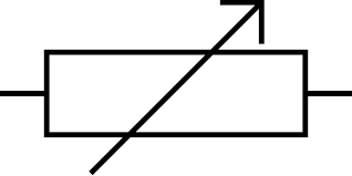
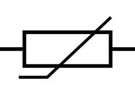
state the symbol for a variable resistor
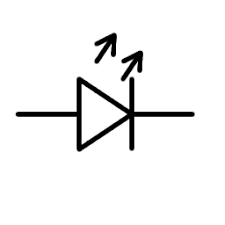
state the symbol for an LED
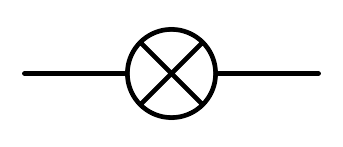
state the symbol for a lamp
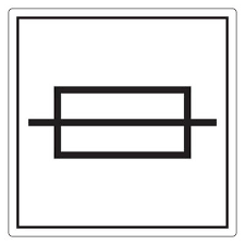
state the symbol for a fuse
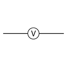
state the symbol for a voltmeter
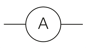
state the symbol for an ammeter
state the symbol for a thermistor
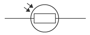
state the symbol for an LDR
state what is needed for electrical charge to flow through a closed circuit
source of potential difference
state what electrical current is
rate of flow of electrical charge
explain how the size of electrical current is related to electrical charge
size of electrical current is the rate of flow of electrical charge
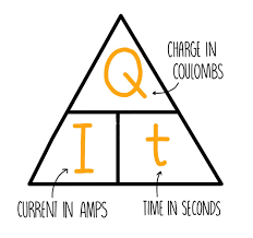
state the equation that links current, charge and time
charge(C) = current (A) x time (s)

state the symbol equation that links current, charge and time
Q (C) = I (A) x t (s)
state what the current through a component depends on
resistance of the component
potential difference across the component
state the effect of increasing resistance of a component on the current through it with a given resistance
increasing resistance decreases current
they have an inversely proportional relationship
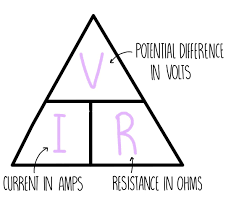
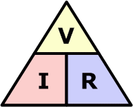
state the equation linking potential difference, current and resistance
potential difference (V) = current (A) x resistance (Ω)

state the symbol equation linking potential difference, current and resistance
p.d (V) = I (A) x R (Ω)
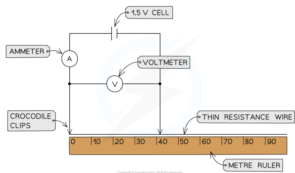
core practical - investigate how the length of a wire at constant temperature affects the resistance of an electrical circuit (method)
set up the apparatus by connecting two crocodile clips to the thin resistance wire a distance of 10cm apart
set the power of the power supply to 1.5V
connect the wire, using clips, to the rest of the circuit
record the initial current from the ammeter and the potential difference from the voltmeter
move the clips apart further in 10cm intervals
take new potential difference and current readings
continue until the crocodile clips are 1m apart
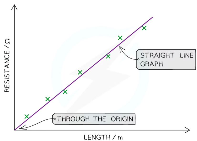
core practical - investigate how the length of a wire at constant temperature affects the resistance of an electrical circuit (results)
as the distance between the crocodile clips increases (length of wire increases), the resistance will increases
therefore resistance is directly proportional to the length of the wire
state the independent variable in the investigation of how the length of a wire at constant temperature affects the resistance of an electrical circuit
length of resistance wire
state the dependent variable in the investigation of how the length of a wire at constant temperature affects the resistance of an electrical circuit
resistance
state the control variable in the investigation of how the length of a wire at constant temperature affects the resistance of an electrical circuit
potential difference of power supply
temperature of wire
core practical - investigate how the combination of resistors affects the resistance of an electrical series circuit (method)
connect the first circuit with a battery of 4V with a resistor, a voltmeter connected in parallel to the resistor and an ammeter connected in series to the resistor
close the switch in the circuit and record the reading on the voltmeter and ammeter
open the switch in the circuit
repeat step 2 with another resistor in series with the other resistor
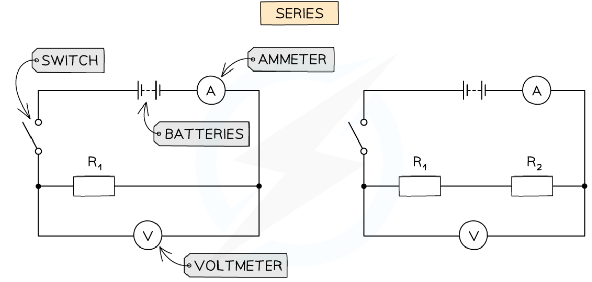
core practical - investigate how the combination of resistors affects the resistance of an electrical series circuit (results analysis)
resistance across one resistor is the same as the resistance of 2+ resistors combined
this is because the electrons flow through just one path, through both resistors, so the current does too
core practical - investigate how the combination of resistors affects the resistance of an electrical parallel circuit (method)
set up the circuit with a power of 4V with a resistor, another resistor in parallel, a voltmeter in parallel and an ammeter in series to both resistors
close the switch in the circuit and record the readings from the voltmeter and ammeter
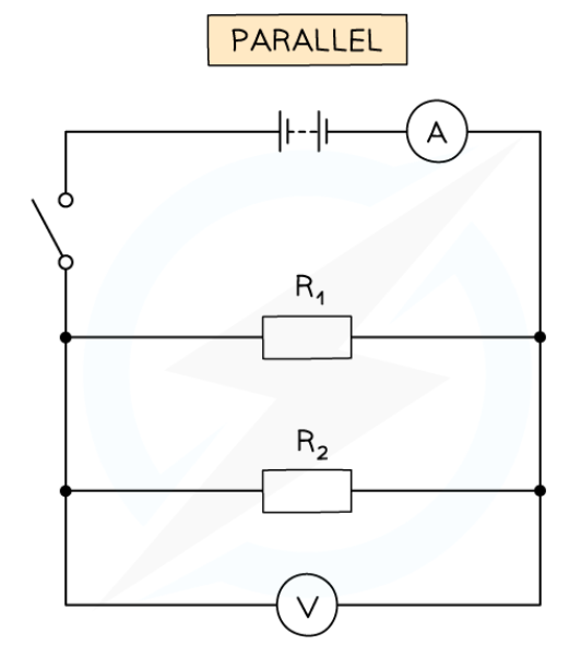
core practical - investigate how the combination of resistors affects the resistance of an electrical parallel circuit (results analysis)
the resistance of the resistors in parallel will be less than the total resistance of one or more resistors in series
this is because the electrons are split between the different paths. but the resistors still have the same potential difference across them
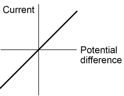
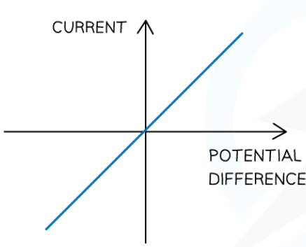
explain the relationship between current through an ohmic conductor and potential difference across it
directly proportional
meaning resistance remains constant as current changes
explain what the graph showing the relationship between current through an ohmic conductor and potential difference across it looks like
linear
goes through origin
positive correlation
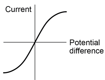
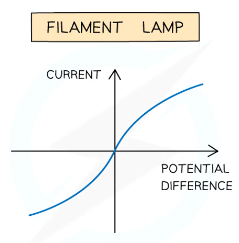
explain the relationship between current through a filament lamp and potential difference across it
directly proportional until a certain point
as when the current increases, the potential differences increases
however, when electrons flowing through the wire collide with ions in the wire, the temperature increases
as the kinetic energy of the wire increases
causing the resistance of the circuit to increases, decreasing the current through the circuit
explain what the graph showing the relationship between current through a filament lamp and potential difference across it looks like
not linear
goes through origin
positive correlation
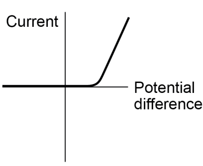
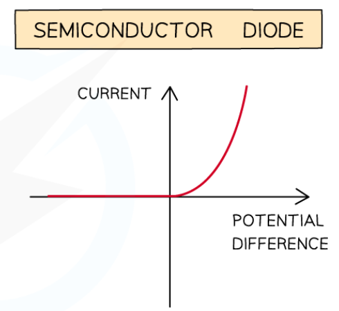
explain what the graph showing the relationship between current through a diode and potential difference across it looks like
sharp increases on right side of the graph
when the direction of the diode reverses, reverse bias occurs
state what happens to the resistance of a thermistor when temperature increases
resistance decreases
state an example of when the application of thermistors in a circuit is needed
thermostat
state what happens to the resistance of an LDR as light intensity increases
resistance decreases
state an example of when the application of LDRs in a circuit is needed
switching lights on when it gets dark
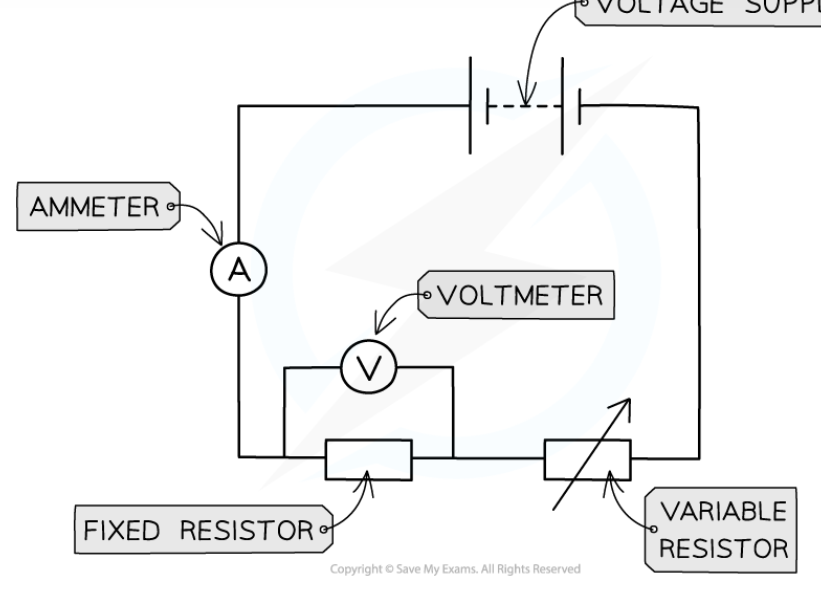
state the method of how to investigate the I-V characteristics of a filament lamp/diode/resistor at constant temperature in a circuit
set up a circuit with a power supply, a filament lamp/diode/resistor, an ammeter in series, a variable resistor in series and a voltmeter in parallel
vary the voltage across the filament lamp/diode/resistor by changing the resistance of the variable resistor
take a wide range of voltage readings
for each voltage reading taken, record the current reading 3 time and calculate an average current
increase the voltage by 0.5V and repeat steps 2 and 3
switch off the circuit between readings to prevent heating of components and wires
reverse the terminals of the power supply to get negative voltage and current readings
state the expected results of the investigation to determine the I-V characteristics of a filament lamp at constant temperature in a circuit
the I-V graph should display a non-linear line
as the filament lamp is a non-ohmic conductor
meaning the resistance of the filament lamp doesn’t remain constant due to the changes in voltage
state the expected results of the investigation to determine the I-V characteristics of a diode at constant temperature in a circuit
the I-V graph should display a non-linear line
as the diode is non-ohmic conductor
meaning the resistance of the diode doesn’t remain constant due to the changes in voltage
state the expected results of the investigation to determine the I-V characteristics of a resistor at constant temperature in a circuit
the I-V graph should display a linear line
as the resistor is an ohmic conductor
meaning the resistance of the resistor remains constant despite the changes in voltage
state what is observed in series circuits
there is the same current through each component
the total potential difference is shared between components
the resistance across components is equal
state the equation to calculate the total resistance across components in a series circuit
Rₜₒₜₐₗ = R₁ + R₂
state what is observed in parallel circuits
the potential difference across each component is the same
the total current through the circuit is the sum of current through each component
the total resistance of 2+ resistors is less than the resistance of the smallest individual resistor
state how to calculate the total current in a parallel circuit
Iₜₒₜₐₗ = I₁ + I₂
state what the supply of mains electricity in the uk is
ac supply
state what the frequency of domestic electricity supply in the uk is
50Hz
state what the voltage of domestic electricity supply in the uk is
230V
what is the difference between direct (dc) and alternating (ac) potential difference
ac - direction of flow of electrons constantly changes
dc - direction of flow of electrons doesn’t change
state how most electrical appliances are connected to the mains supply
using three-core cables
state what the brown insulation in wires means
the wire is a live wire
state what the blue insulation in wires means
the wire is a neutral wire
state what the green and yellow stripes insulation in wires means
the wire is an earth wire
state what the purpose of a live wire is in a circuit
carries the alternating (ac) potential difference from the supply
state what the purpose of a neutral wire is in a circuit
completes the circuit
state what the purpose of an earth wire is in a circuit
safety wire to stop the appliance becoming live
state what the potential difference between live wires and earth wires is
230V
state the voltage of an earth wire
0V
state the voltage of a neutral wire
~0V
state the only time when an earth wire carries current
when there is a fault in the circuit
explain why live wires are dangerous even when a switch in the mains circuit is open
if the circuit became complete, a large potential difference would start
this could electrocute someone
explain the dangers of providing any connection between the live wire and earth
a shock or fire will occur
as a connection between the live wire and earth completes the circuit between them
state the equation linking power, potential difference and current
power (W) = voltage (V) x current (A)
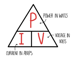
state the symbol equation linking power, potential difference and current
P (W) = V (V) x I (A)

state the equation linking power, current and resistance
power (W) = (current)² (A) x resistance (Ω)

state the symbol equation linking power, current and resistance
P (W) = (I)² (A) x R (Ω)
state the reason for the design of electrical appliances
to bring about energy transfers
state what the amount of energy an appliance transfers depends on
how long the appliance is switched on for
power of the appliance
describe how a torch transfers energy from batteries to the kinetic energy of heating devices
energy is initially in the chemical store of the torch’s batteries
when the torch is switched on, the circuit is completed
the kinetic energy of the electrons flowing in the current is transferred to the thermal store of the bulb
describe how a vacuum cleaner transfers energy from ac mains supply to the kinetic energy of electric motors
energy is initially stored in the chemical store of the vacuum’s power station
when the vacuum is connected to the ac mains supply, the circuit is completed
the kinetic energy of the electrons flowing in the current is transferred to the kinetic store of the motor and the thermal store of the surroundings
state when work is done in a circuit
when charge flows
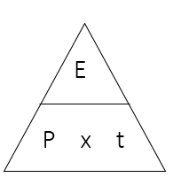
state the equation linking energy, power and time
energy (J) = power (W) x time (s)

state the symbol equation linking energy, power and time
E (J) = P (W) x t (s)
state the equation linking energy, charge and voltage
energy (J) = charge (C) x voltage(V)
state the symbol equation linking energy, charge and voltage
E (J) = Q (C) x V (V)
explain how the power of a circuit device is related to the potential difference across it
if the potential difference increases, the power increases
explain how the power of a circuit device is related to the current through it
if the current increases, the power increases
explain how the power of a circuit device is related to the energy transferred over a given time
if power increases, the rate of energy transfer increases
state what the power of an appliance is
amount of energy it transfers by electrical work every second
describe the relationship between the power ratings for domestic electrical appliances and the changes in stored energy when they are in use
power rating of an appliance is how much energy it needs to work
the more energy transferred per second by the appliance, the higher the power rating
state what the national grid is
system of cables and transformers
linking power stations to consumers
state how electrical power is transferred from power stations to consumers
national grid
state why step-up transformers are used
to increase potential difference
and reduce current
from the power station
to the transmission cables
state why step-down transformers are used
to decrease potential difference
and increase current
for domestic use
explain why the national grid system is an efficient way to transfer energy from power stations to transmission cables
its use of step-up and step-down transformers
as the current generated by power stations is greater than needed for domestic use
causing it to need to be transferred across the uk by cables
and as electricity is transferred over large distances, resistance in the wires causes heating
which increases unwanted energy transfers
so increasing the potential difference transfers a larger amount of power using a smaller current
which results in less unwanted energy transfers
explain why the national grid system is an efficient way to transfer energy from transmission cables to homes and buildings
its use of step-up and step-down transformers
as the current generated by power stations is greater than needed for domestic use
causing it to need to be transferred across the uk by cables
and as electricity is transferred over large distances, resistance in the wires causes heating
so decreasing the potential difference transfers a smaller amount of power using a larger current
which results in more energy transfers by heating
allowing the power to reach the level found in homes and buildings
explain how insulating materials can become charged through friction
through friction, negatively-charged electrons are transferred
the material that loses electrons will now have a net positive charge
the material that gains electrons will now have a net negative charge
state what happens when two electrically-charged objects are brought close together
they exert a force on each other
state what happens when two objects with like charges are brought close together
they repel
state what happens when two objects with opposite charges are brought close together
they attract
state what type of force attraction and repulsion between electrically-charged objects is
non-contact force
state how static electricity is produced
static electricity is caused by the build up of stationary charge on a surface
explain how sparks are produced by rubbing surfaces
build up of electrostatic charge causes sparks
sparks occur when there is a large potential difference between surfaces
when there is contact/friction between surfaces, current flows between them
explain how magnets are evidence that charged objects exert force on each other when not in contact
a magnet has two poles; north and south
each pole is charged opposite to the other
like poles will repel each other
opposite poles will attract
a magnetic force is experienced by any magnetic material in a magnetic field
when two magnets are brought together in a magnetic field, the poles will attract or repel even though there is no contact between them
explain how the transfer of electrons between objects can explain static electricity
when there is friction between surfaces, there is a transfer of electrons
electrons building up on a surface produces static electricity
creating an excess net negative charge on the surface receiving electrons
state when a charged object is created
when the objects creates an electrical field around itself