computer hardware component's flashcards (copy)
1/9
Earn XP
Name | Mastery | Learn | Test | Matching | Spaced | Call with Kai | Chat |
|---|
No analytics yet
Send a link to your students to track their progress
10 Terms
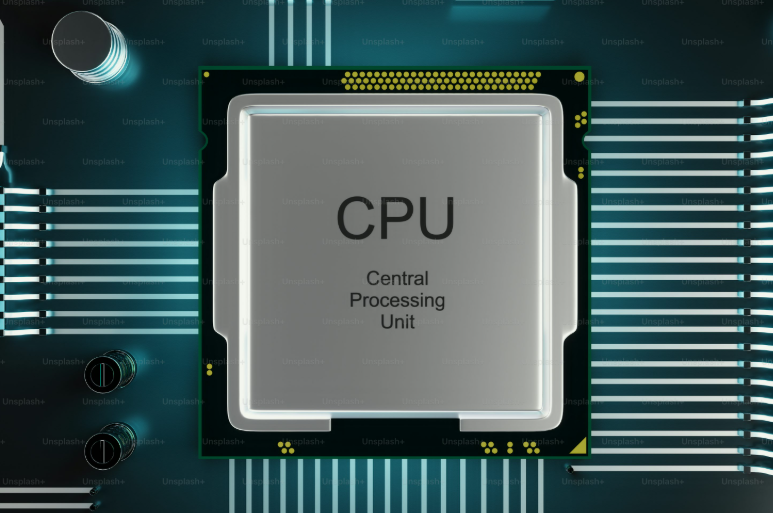
CPU(CENTRAL PROCESSING UNIT)
CPU WORK :
Performing arithmetic and logical operations via the Arithmetic Logic Unit (ALU)
Controlling data flow between memory, input/output devices, and other components through the Control Unit (CU
Fetching, decoding, and executing instructions in a cycle known as the instruction cycle
CPU PLACEMENT :
The CPU is typically placed at the center of the system architecture:
Connected directly to main memory (RAM) for fast access to instructions and data
CPU INTERCONNECTION :
Component | Connection Type | Purpose |
|---|---|---|
Memory | Address, Data, Control Bus | Transfers instructions and data |
I/O Devices | I/O Bus or Controllers | Sends/receives data to/from peripherals |
Other CPUs | Multiprocessor Bus or Switch | Enables parallel processing in multi-core systems |
Cache Memory | Internal Bus | Speeds up access to frequently used data |
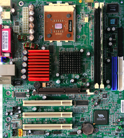
MOTHERBOARD
MOTHERBOARD WORK :
The motherboard is the central backbone of a computer system. It connects and coordinates all the major components, allowing them to communicate and work together efficiently.
MOTHERBOARD PLACEMENT :
Component | Placement on Motherboard | Purpose |
|---|---|---|
CPU Socket | Center or top-center | Holds the processor |
RAM Slots | Next to CPU socket | Houses memory modules |
Chipset (Northbridge/Southbridge) | Near CPU and expansion slots | Manages data flow between components |
PCIe Slots | Lower half | For GPU, network cards, etc. |
INTERCONNECTION :
Traces: Copper pathways etched into the board that carry signals.
Buses: Data highways like the front-side bus (FSB) and PCIe lanes.
Connectors: Physical interfaces for cables and modules (e.g., SATA, USB headers).
Chipset: Acts as a traffic controller between CPU, RAM, and peripherals.
Power Rails: Deliver voltage to different zones of the board.
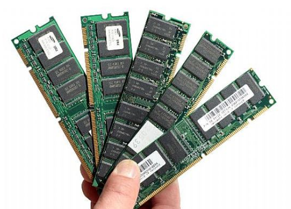
RAM(RANDOM ACCESS MEMORY)
RAM WORK :
RAM (Random Access Memory) is the short-term memory of a computer, crucial for fast data access and smooth multitasking. Let’s break it down
Boosts Performance: More RAM allows smoother multitasking and faster program execution.
Volatile Memory: Data is lost when the system powers off.
RAM PLACEMENT :
Component | Location on Motherboard | Description |
|---|---|---|
RAM Slots | Near the CPU socket | Long slots for DIMM modules |
DIMM Modules | Inserted vertically into slots | Physical RAM sticks |
Channel Layout | Dual-channel or quad-channel | Optimizes memory bandwidth |
RAM INTERCONNENTION :
Memory Bus: Connects RAM to the CPU via the memory controller.
Address & Data Lines: Carry instructions and data to/from RAM.
Chipset Coordination: Northbridge (or integrated controller) manages RAM traffic.
Power Supply Rails: Provide voltage to RAM modules.
Fly-by Topology: Used in DDR3/DDR4 for signal timing and integrity
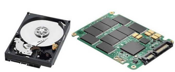
STORAGE(SSD/HDD)
SSD-SOLID STATE DRIVE
HDD-HARD DISK DRIVE
SSD/HDD WORK :
Feature | SSD (Solid State Drive) | HDD (Hard Disk Drive) |
|---|---|---|
Storage Type | Flash memory (no moving parts) | Magnetic platters with spinning disks |
Speed | Very fast read/write speeds | Slower compared to SSD |
Durability | More shock-resistant | Prone to mechanical failure |
SSD/HDD PLACEMENT :
2.5-inch SSD/HDD: Mounted in drive bays, connected via SATA cable.
M.2 SSD: Slotted directly into the M.2 connector on the motherboard.
NVMe SSD: Uses PCIe lanes for ultra-fast data transfer; fits into M.2 or PCIe slots.
3.5-inch HDD: Common in desktops; mounted in larger drive bays.
SSD/HDD INTERCONNECTION :
SATA Interface:
Used by both SSDs and HDDs (2.5" or 3.5")
Requires SATA data cable + SATA power cable from PSU
M.2 Interface:
Direct motherboard connection
NVMe SSDs use PCIe lanes; SATA M.2 SSDs use SATA bus
Power Supply:
15-pin SATA power connector from PSU
Data Transfer:
SATA: Up to 6 Gbps
NVMe (PCIe Gen 3/4/5): Up to 32 Gbps or more
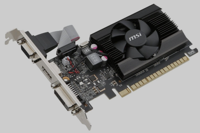
GPU(GRAPHIC PROCESSING UNIT)
GPU WORK :
The Graphics Processing Unit (GPU) is a specialized processor designed to handle complex visual and parallel computing tasks. It’s essential for gaming, video editing, 3D rendering, and AI workloads.
Graphics Rendering: Processes and displays images, animations, and video.
GPU PLZCEMENT :
GPU Type | Placement Location | Connection Interface |
|---|---|---|
Discrete GPU | Inserted into PCIe x16 slot | PCI Express (PCIe) |
Integrated GPU | Built into CPU or motherboard | Shares system memory |
External GPU | Connected via Thunderbolt/USB-C | External enclosure |
GPU INTERCONNECTION :
PCIe Interface: High-speed data link between GPU and CPU/memory.
VRAM (Video RAM): Dedicated memory for textures, frame buffers, and shaders.
Power Connectors: 6-pin, 8-pin, or 12-pin connectors from PSU for extra power.
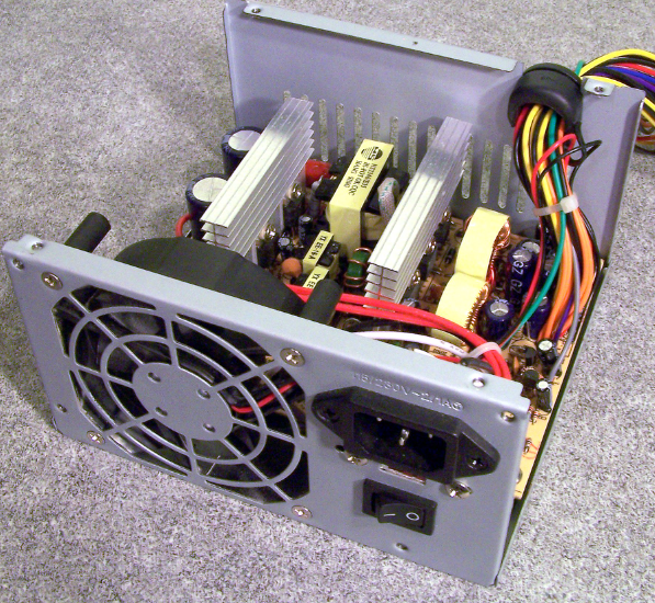
PSU(POWER SUPPLY UNIT)
PSU WORK :
The PSU is the heart of a computer’s electrical system. It converts wall outlet AC power into usable DC power for all internal components.
AC to DC Conversion: Transforms 230V AC (in India) into multiple DC voltages (typically 3.3V, 5V, and 12V).
Voltage Regulation: Maintains stable output despite load changes.
Power Distribution: Supplies energy to motherboard, CPU, GPU, drives, fans, and peripherals.
Protection Mechanisms: Includes overvoltage, overcurrent, and short-circuit protection.
PSU PLACEMENT :
Form Factor
Typical Location in Case
Notes
ATX
Bottom or top rear
Most common in desktops
SFX
Compact cases
Used in mini-ITX builds
TFX
Slim desktops
Less common
PSU INTERCONNECTION :
Connector Type | Purpose | Connects To |
|---|---|---|
24-pin ATX | Main power for motherboard | Motherboard |
SATA Power | Powers SSDs/HDDs/optical drives | Storage devices |
Molex | Legacy devices, fans, RGB | Older peripherals |
FDD (Floppy) | Obsolete | Floppy drives (rarely used) |
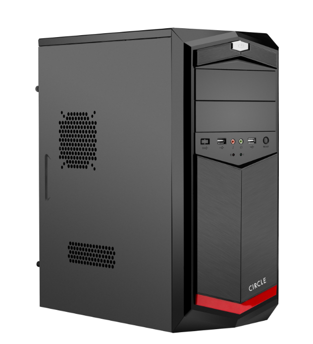
CABINET
CABINET WORK :
Protection: Shields internal components from dust, moisture, and physical damage.
Component Mounting: Provides slots and bays for motherboard, PSU, GPU, drives, etc.
Cable Management: Keeps wiring organized to improve airflow and reduce clutter.
CABINET PLACEMENT :
Cabinet Type
Typical Placement
Use Case
Tower (ATX/Micro)
On or under desk
Standard desktops
Mini-ITX
Compact spaces, shelves
Small form factor builds
Server Rack
Data centers
Enterprise/server environments
Horizontal Case
Media centers
HTPCs or retro-style setups
CABINET INTERCONNECTION :
cabinet is connect with motherboard,psu,gpu,ssd,hdd,cooler,front panel.
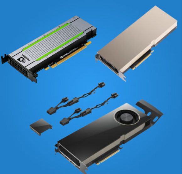
GRAPHIC CARDS
GRAPHIC CARD WORK ;
Image Rendering: Converts data into visuals for display—2D, 3D, and video.
Parallel Processing: Executes thousands of tasks simultaneously, ideal for gaming and AI.
Video Encoding/Decoding: Accelerates media playback and streaming.
Ray Tracing & AI Graphics: Simulates realistic lighting and enhances visuals using machine learning.
VR/AR Support: Powers immersive environments with high frame rates and low latency.
GRAPHIC CARD PLACEMENT :
Form Factor
Placement Location
Use Case
Discrete GPU
PCIe slot on motherboard
Gaming, design, AI, rendering
Integrated GPU
Inside CPU or motherboard
Basic tasks, office work
External GPU (eGPU)
Connected via Thunderbolt
Portable graphics boost for laptops
GRAPHIC CARD INTERCONNECTION :
graphic card is interconnect with gpu,vram,power supply,moniter,cpu,cooling system.
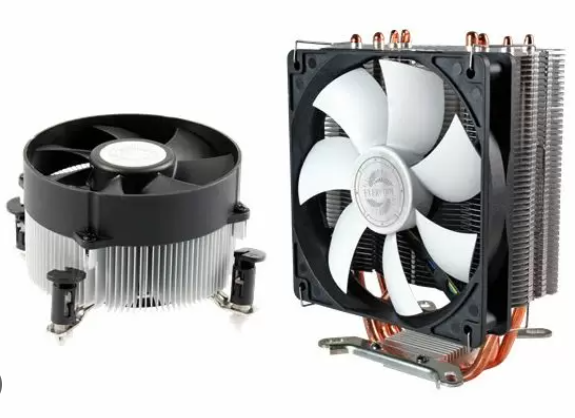
CPU COOLER
CPU COOLER WORK :
Purpose: It dissipates heat generated by the CPU to prevent overheating and maintain performance.
Types:
Air Coolers: Use a heatsink and fan to draw heat away from the CPU.
Liquid Coolers (AIO): Circulate coolant through a loop to transfer heat from the CPU to a radiator.
CPU COOLER PLACEMENT :
Air Coolers:
Mount directly on the CPU socket.
Fan should push air through the heatsink toward the rear exhaust fan.
Liquid Coolers (AIO):
Top Mount: Ideal for airflow and longevity; air accumulates in the radiator, not the pump.
Bottom Mount: Not recommended; air can gather in the pump, reducing efficiency
CPU COOLER INTERCONNECTION :
Backplate: Installed behind the motherboard to secure the cooler.
ARGB/Lighting:
Use 3-pin 5V connectors for RGB lighting if supported.
Daisy-chain fans or use a hub for synchronized lighting.
Cable Management:
Use cable ties or Velcro strips to keep wires tidy and airflow unobstructed.
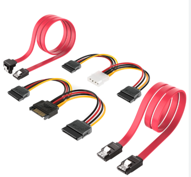
SATA(SERIAL ADVANCED TECHNOLOGY ATTACHMENT)
SATA WORK :
Purpose: SATA is a high-speed interface used to connect storage devices like HDDs, SSDs, and optical drives to the motherboard.
Data Transfer: Uses serial communication for faster and more efficient data transmission compared to older PATA interfaces.
SATA PLACEMENT :
Motherboard:
SATA ports are usually located near the bottom-right edge.
Labeled as SATA1, SATA2, etc., and often color-coded.
Storage Devices:
Optical drives (DVD/CD) may also use SATA and are placed in external-facing bays.
SATA INTERCONNECTION :
Cables:
Data Cable: 7-pin connector (3 grounds, 4 data lines).
Power Cable: 15-pin connector supplying 3.3V, 5V, and 12V
Controller Modes:
IDE Mode: Legacy compatibility.
AHCI Mode: Enables hot swapping and native command queuing.
RAID Mode: Combines multiple drives for redundancy or performance