Reservoir Fundamentals KNW1
1/84
There's no tags or description
Looks like no tags are added yet.
Name | Mastery | Learn | Test | Matching | Spaced |
|---|
No study sessions yet.
85 Terms
porosity
ratio of pore volume to bulk volume
phi = Vp/Vb => 0<phi<1
pore throat factors & responsibilities
determines permeability
their number, size & distribution controls:
resistivity
flow
capillary force
porosity factors
size
shape
distribution (sorting)
arrangement (packing)
permeability
capacity of a porous material for transmitting a fluid controlled by the size of the pore throats & capillaries [mD]
1mD = 10e-15 m2
Darcy law
description of single-phase flow in porous media
q_darcy = phi*velocity = -k//µ (pressure gradient-rho*g)
permeability tests
core flooding in lab
pressure transient test for field
reservoir velocities
volumetric flux: discharge of a volume per time Q=dV/dt [m3/s]
darcy velocity: the velocity of porous medium would be an open volume q=Q/A [m/s]
interstitial velocity: the actual velocity of a fluid element as the fluid moves through the pore space in the porous medium v=q/phi [m/s]
permeability upscaling
changing from the micro to continuum scale via porosity REV
- flow parallel to the layers → arithmetic avg: k_avg = ∑kihi/∑hi
- flow perpendicular to the layers → harmonic avg: k_avg = ∑Li/∑(Li/ki)
wiener bounds
The effective property of a heterogeneous media is bounded between harmonic and arithmetic averages.
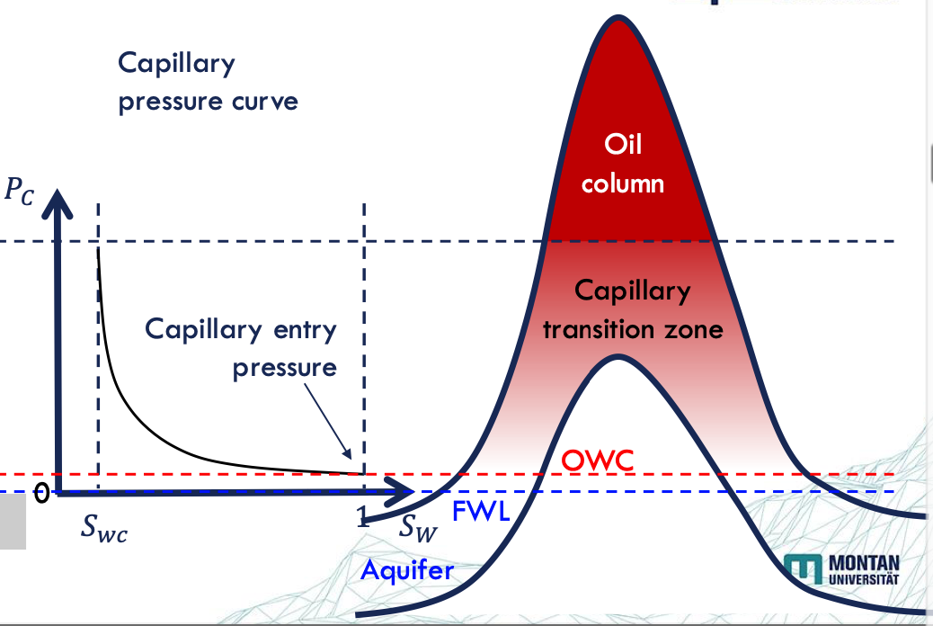
fluid pressure
the weight of the fluid column above the reservoir depth
pfl = p0+rho*g*z p0+G*z
density order of a reservoir fluids
water>oil>gas
fluid contact tests
fluid pressure regimes
fluid densities from formation samples
capillary pressure data from core samples
seismic survey
total pressure of reservoir
weight of the formation rock & fluids
transition zone factors
rock structure
heterogeneity
total pore volume
volume of fluid filled pores
Vp=Vw+Vo+Vg
fluid saturation
the proportion of each fluid within the total pore volume
Si = Vi/Vp => Sw+So+Sg=1
fluid saturation of heterogeneous formation
saturation varies through the layers thus we go with the avg saturation
So,avg = ∑phi*hi*Soi/∑phi*hi
capillary rise
a competition between the capillary force & gravity
p_c = p_g
(2*sigma(F1F2)*cosø)/r = rho*g*h
PVT experiment
recombine crude oil & gas in the right proportions
control pressure by Hg-pump pressure gauge at const. temp →injected Hg acts as piston controlling the volume in the pressure cell
main parameters of reservoir volume
solution gas oil ratio Rs=Vgs/Vos [scf/stb]
oil formation volume factor Bo=Vor/Vos [rb/stb]
gas formation volume factor Bg=Vgr/Vfg [rb/scf]
Vgs=Vsg+Vfg
Vsg = volume of solution gas
Vfg = volume of free gas
Vos = volume of oil surface cond.
Vor = volume of oil res. cond.
fluid types
incompressible → liquids under pressure maintenance conditions c = 0
slightly compressible → liquids under pressure depletion conditions c = const
compressible → gases & supercritical fluids under pressure variation c(p)
compressibility by volume & density
fractional changes in volume due to unit change in pressure [psi-1]:
cv = - 1/V * ∂V/∂p
cp= 1/rho * ∂rho/dp
![<p>fractional changes in volume due to unit change in pressure [psi<sup>-1</sup>]: </p><p>cv = - 1/V * ∂V/∂p</p><p>cp= 1/rho * ∂rho/dp</p>](https://knowt-user-attachments.s3.amazonaws.com/2f453d7f-e1ae-45de-b389-9a4c5b8fabdd.png)
surface (stock tank) pT-condition
p = 14.696 psi
T = 60°F =15,556 °C 16°C
ideal gas EOS
low pressure pV = nRT
high pressure pV = ZnRT
compressibility z factor parameters
gas composition
temp
pressure
sensible heat
changes the temp of a substance w/o changing its state
latent heat
changes the state of a substance w/o changing its temp
water recharge
a doublet system w/ a hot producer and a cold re-injector:
injection into a single-phase liquid water region: increase or maintain pressure
injection of cold water into two-phase (steam-water) reservoir: decrease pressure & temp until condensation
injection of cold water into a superheated steam zone: increase pressure as long as no two phase zone develops
solubility
the ability of a substance to be dissolved in the solvent
increases w/ pressure
decrease w/ increasing temp & salinity
miscibility
the ability of one substance to dissolve in another substance forming a homogenous solution (usually liquid)
critical locus
the max pressure at which two phases can exist
cumulative gas volume formula
F = ∑Vg
expansion factor formula
E = Vg/Vm,g
compressibility z-factor formula
Z = p/psc Tsc/T 1/E = 35.37 p/ET
shrinkage factor formula
cbs = Vo in the separator/Vo at BP
GOR
the ratio of gas to oil produced at stock-tank cond.
GOR = Vg/Vo in the separator
Derivation of Field Relevant Parameters
flash (FE): liberation process in reservoir
differential (DLE): liberation process around well → same as flash experiment starts at bp pressure and after each step, gas is removed from the cell by const pressure Hg-injection
oil formation volume factor
Bo = Vo/cbf [rb/stb]
![<p>Bo = V<sub>o</sub>/c<sub>bf</sub> [rb/stb]</p>](https://knowt-user-attachments.s3.amazonaws.com/3edc7a68-7f8d-4549-bcd6-6480ffc48207.png)
solution gas oil ratio
the solubility of natural gas in crude oil depending on temp, pressure & composition of o&g
Rsi - Rs = 5.615F/cbf [scf/stb]
![<p>the solubility of natural gas in crude oil depending on temp, pressure & composition of o&g</p><p>R<sub>si</sub> - R<sub>s</sub> = 5.615F/c<sub>bf</sub> [scf/stb]</p>](https://knowt-user-attachments.s3.amazonaws.com/8ed0704d-3c97-4aa9-994b-efd03d56d7ff.png)
gas formation volume factor
Bg = 1/ 5.615E [rb/scf]
![<p>Bg = 1/ 5.615E [rb/scf]</p>](https://knowt-user-attachments.s3.amazonaws.com/e9a74ceb-b52b-44cd-a31c-66c1e8a345f8.png)
Apparent molecular weight formula
Ma = ∑yiMi
Volume at standard conditions formula
RTsc/psc
gas density formula
rho = m/V = pMa/ZRT
specific volume formula
v = V/m = ZRT/pMa = 1/gas density
gas expansion factor formula
Eg = 1/Bg
gas formation volume factor
Bg = Vres/Vsc = 0.02827 ZT/p [ft3/scf] = 0.005035 ZT/p [rb/scf] = 351.64 ZT/p [m3/sm3]
gas specific gravity formula
gamma g = rhogas,sc/ rhoair,sc = Ma/Mair = Ma/28.96
critical pT formula
pc = ∑yipci
Tc = ∑yiTci
reduced pT formula
pr = p/pc
Tr = T/Tc
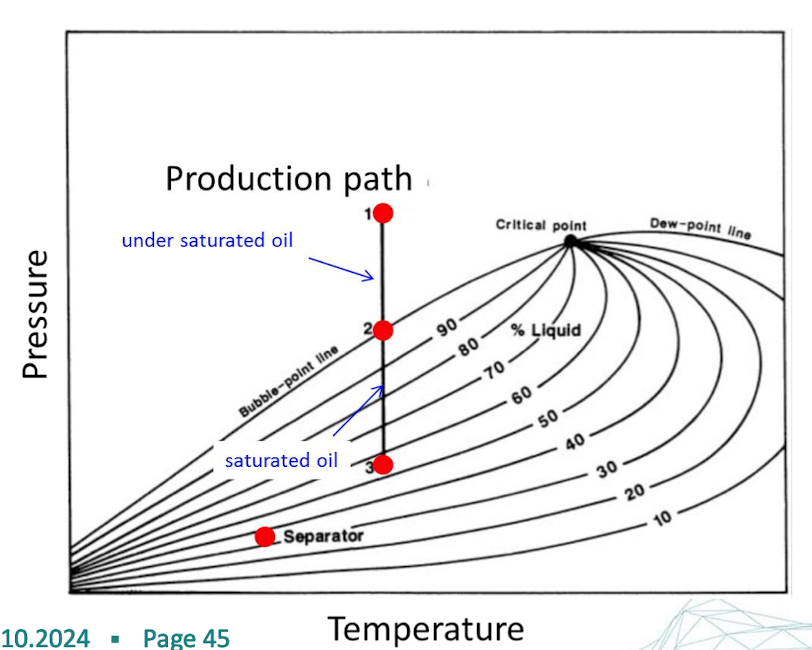
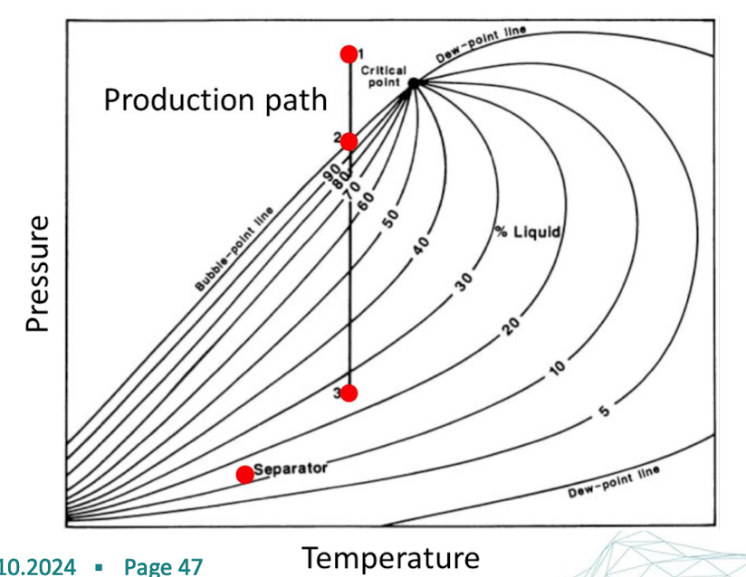
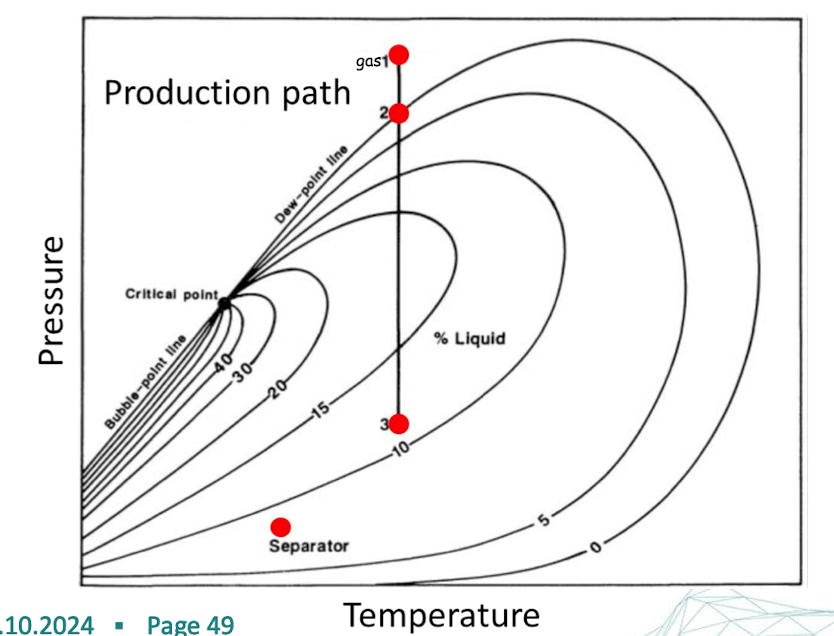
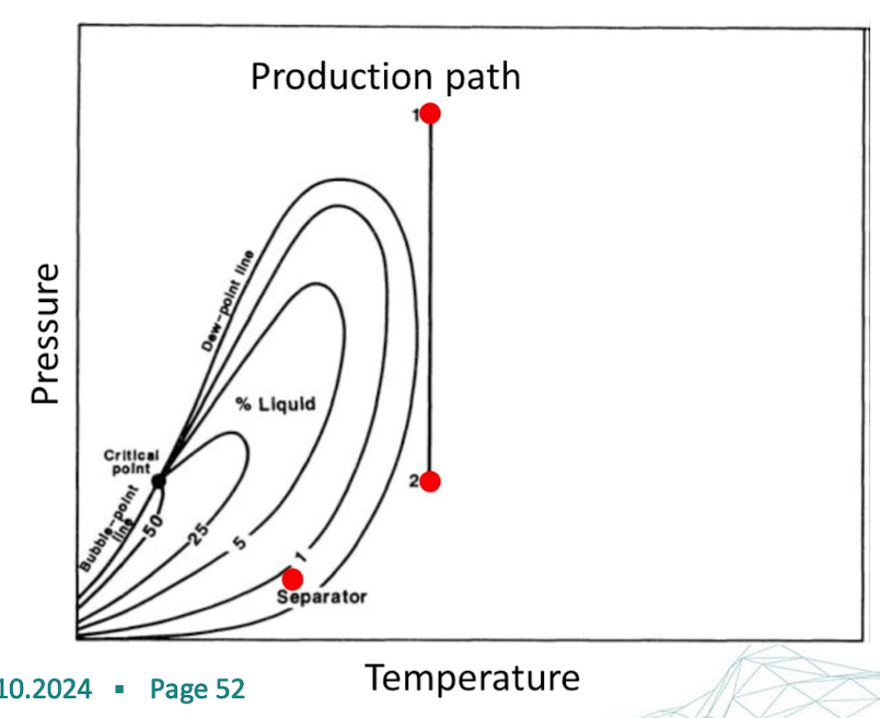
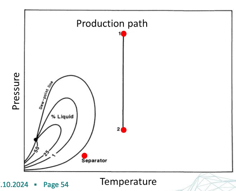
quality lines
determines the percentage of liquid & gas at the given PVT conditions
black oil reservoir
includes large, heavy, nonvolatile molecules
covers a wide temp range
aka low shrinkage crude oil or ordinary oil
brown to dark green color
volatile oil reservoir
more intermediate molecules (ethane to hexane)
smaller temp range
Tc closer to the Tres
release large amount of gas in the reservoir
lower amount of oil in the separator
aka high shrinkage crude oil or near critical oil
Tc >Tres
greenish to orange color
retrograde gas reservoir
Tc<Tres<Tct
fewer heavy HC
smaller temp range
reservoir is initially in gas phase & as the pressure decreases below the dew point, liquid condenses
translucent or slightly coloured
aka gas condensate
wet gas reservoir
The hydrocarbon mixture exists as a gas in the reservoir and two-phase in the surface
Tres>Tc
translucent
smaller HC molecules
entire envelope is below Tres
dry gas reservoir
The hydrocarbon mixture exists as a gas both in the reservoir and in the surface since it doesn’t have enough heavier molecules to form liquid in the separator or field
Tres>Tc
primarily methane w/ some intermediates
separator flash expansion
stimulates the surf separation conditions of reservoir fluid
PVT cell is connected to a separator system
the separator maintains a fixed pT-condition that mimics surface facility conditions
the bp oil is then flashed through the separator system to stock tank conditions
FCM process
injecting a primarily slug that is miscible w/ the crude oil
material balance
Keep track of mass and be able to convert form reservoir to surface conditions to predict recovery & determine the principle res drive mechanism
oil volume
Vo = V*NG*phi*Soi
total oil volume at sc
N = V*NG*phi*Soi/Boi
connate water
water naturally trapped in rock pores due to capillary force → lowest in-situ water saturation
water expansion formula
cw = -1/Swc ∂Swc/∂p due to pressure & effective pore pressure decrease
pot aquifer model
assumes the gas field is in contact with an aquifer, which responds instantly to any decline in reservoir pressure (maintaining pressure) used for
rel. slow production
small aquifers
well connected & high permeable aquifers
reservoir tank model
describes the effective volumetric properties
Oil production formula
N - Np = V*NG*phi*So/Bo
Rf = Np/N = 1 - (Boi*So)/(Bo*Soi)
gas production formula
G - Gp = V*NG*phi*Sgi/Bg
Rf = Gp/G = 1 - (Bgi/Bg) = 1- (pZi/piZ)
Water drive gas res formula
G - Gp = (V*NG*phi*Sgi/Bg)-(We/Bg)
Gp = G(1-(Bgi/Bg)) + We/Bg
Rf = Gp/G = (1 - (Bgi/Bg))+ Bgi(1-Swc-Sgr)/Bg(1-Swc) = 1 - (Bgi*Sgr)/Bg(1-Swc)
Water influx formula
We = Wc∆p = W(Cø+Cw)∆p = Vinv*phi(1-Swc-Sgr)
material balance formula
F = N(E0 + mEg + (1+m)Er) + We = N(Bo-Boi+Bg(Rsi-Rs)) + mNBoi((Bg/Bgi)-1) + (1+m)NBoi(cø+SwcCw/1-Swc)∆p + Wc∆P
m = Vgc/Voc
main drive mechanism
gas cap drive
water drive
solution gas drive
combined drive = gas cap + water
Solution gas drive MBE conditions
energy source: evolved solution gas expansion
RF = 5-30%
m = 0
Cg »Cw => Cw & Cø =0
W = 0
F = NE0
Np(Bo+Bg(Rp-Rs)) = N(Bo-Boi+Bg(Rsi-Rs))
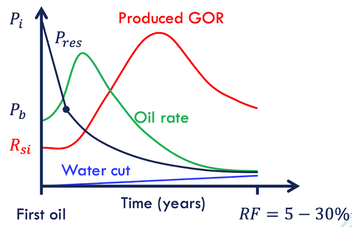
gas solution drive well placement
artificial lift at early stages
steep dip: wells in down dip but not too close to WOC to form a secondary gas cap
shallow dip: well as low as possible to keep was from secondary gas cap

Gas cap drive MBE conditions
Energy source: gas cap & evolved solution gas expansion
RF = 20-50%
Cg »Cw => Cw & Cø =0
W = 0
F= N(E0+mEg)
Np(Bo+Bg(Rp-Rs)) = N(Bo-Boi+Bg(Rsi-Rs))+mNBoi(Bg/Bgi -1)
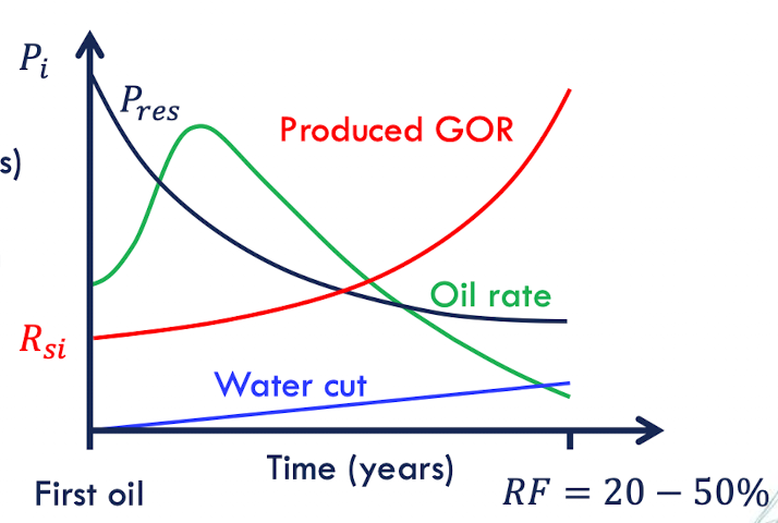
gas cap well placement
higher recover w/ gas driving oil downwards => to avoids the problem of extensive gas production:
Well completions near the bottom of the oil column
horizontal wells low in the oil column
wells should be placed far away from gas cap w/ long life time

types of aquifer
confined/ excxpansion: The aquifer is bounded by impermeable rock so that the reservoir and aquifer together form a volumetrically closed unit. parameters:
compressibility of aquifer water & matrix
relative size of aquifer to HC accumulation
unconfined/ artesian: The reservoir rock outcropped at one or more places where it may be refilled by surface water.
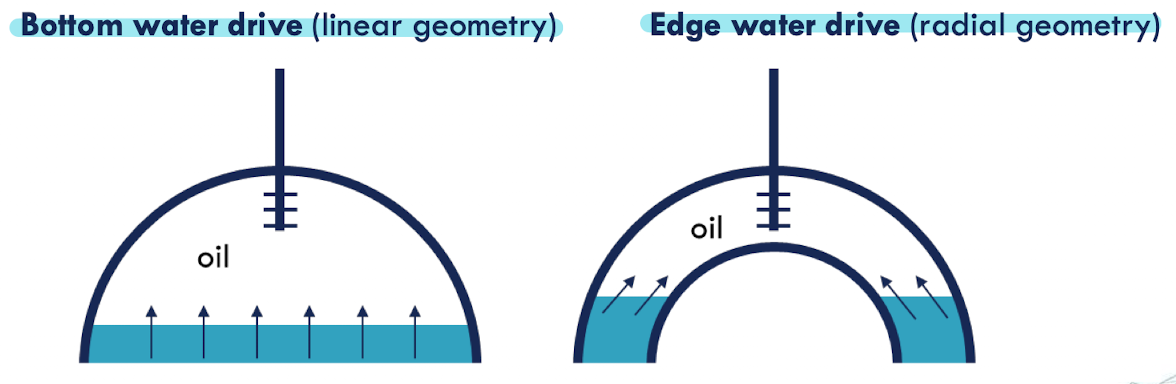
water drive type
bottom water drive → linear geometry
edge water drive→ radial geometry
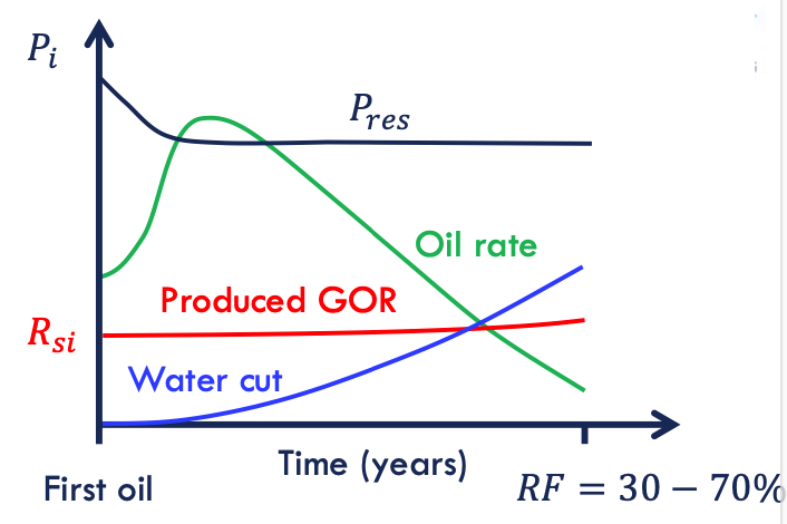
water drive MBE conditions
Energy source: aquifer expansion
RF = 30-70%
Cg »Cw => Cw & Cø =0
m = 0
SwcCw=0
F= NE0 + Wc∆p
Np(Bo+Bg(Rp-Rs)) = N(Bo-Boi+Bg(Rsi-Rs))+Wc∆p
water drive well placement
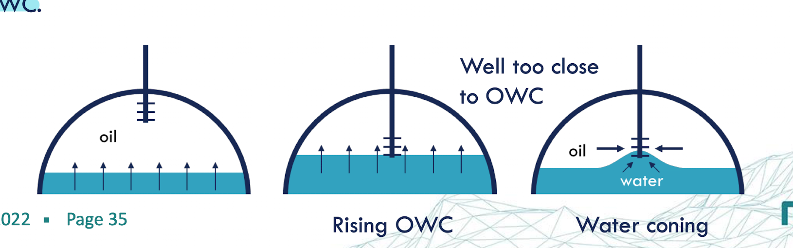
there is an early water breakthrough due to water coning & viscous fingering => well should be perforated high in the oil zone to maximise distance to WOC
combined drive
m = 0
Rp-Rs = 0
W = 0
Rs = 0
SwcCw =0
F =N(E0+Er)
NpBo = N(Bo-Boi)+NBoi(Cø/1-Swc)∆p
Z-factor
describes the deviation of a gas from ideal gas law
Z = Vactual/Videal
solution drive
oil reservoirs that don’t initially contain free gas but develop free gas on pressure depletion. applies when the pressure drops below the BP
water cut
the ratio of water produced compared to the volume of total liquids produced from an oil well
natural drive mechanism
pressure différence between the reservoir & the surf
secondary gas cap
formed by migration of librated gas to the top by buoyancy → weak drive mechanism
depends on:
permeability
permeability aniostrophy
dipping angle
gravity drainage
a type of reservoir drive mechanism caused by the difference in densities of oil & gas & gas segregation → weak and slow mechanism
depends on steepness of the reservoir