AP PHYSICS C E&M EXAM REVIEW
1/67
Earn XP
Description and Tags
Name | Mastery | Learn | Test | Matching | Spaced | Call with Kai |
|---|
No study sessions yet.
68 Terms
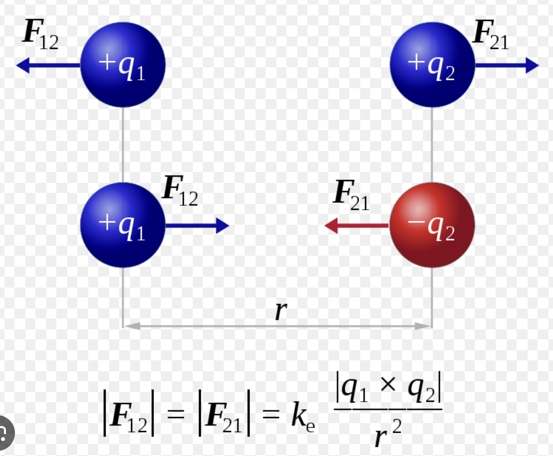
Coulomb’s Law
FE = k * (Q1Q2)/R2
k = 1/4πε0 = 9.0 × 10⁹ Nm2/C2
ε0 = permittivity of free space
Q = charge; SI Unit: C (coulombs)
R = distance (m)
FE = force due to an electric charge
FE = qE
Electric Field (E)
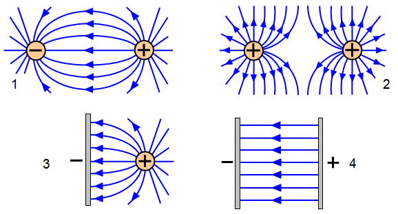
E = FE/Q = kQ/R2
if Q is positive, E and F are parallel → the electric field points in the same direction as the force a positive charge would feel at the location
*Enet = E1 + E2 ….
It is the measure of an electric force at r distance from the source charge (Q)
Electrostatic Induction
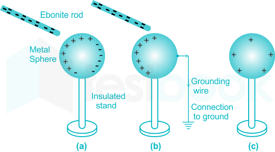
Induction is a method of charging where two objects are placed close together, but are not touched
The charged object is brought closer to an uncharge object. The charge flows between two objects and the uncharged conductive material develop a charge with opposite polarity as the charged object.
Potential (V) & Energy (UX)
∆V = -∫F/q dr = -∫E dr
dV = dU/Q → ∆U = -∫F dr
V = kQ/r
potential difference due to a point charge, Q, at distance r
the voltage is the potential difference (difference in potential energy) between two points in an E field
Vnet = V1 + V2 …
Equipotential Lines
a representation of potential (which exists in 3D) in 2D. Along a line, there is constant potential.
No force or work is required to move a charge along a given equipotential line (since there will be no potential difference)
Since there is no work (W = F * dr) required, the equipotential lines must be perpendicular to electric force and electric field (there is only work if the movement is in the direction that force is applied)
E = -∆V/∆(position) → estimate of E field from equipotential lines
The closer equipotential lines are together, the greater the E-field at the point
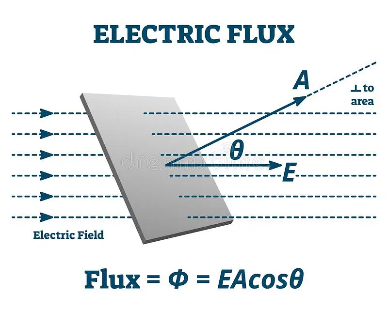
Flux (Φ)
Φ = ∫E dA
(integrating over a closed surface)
Φ = A * F = A * F * cosθ
A = area
Only use when E-field is constant
electric flux is the measure of the electric field through a given surface
Guass’s Law
Φ = ∫E dA = Qenclosed/ε0
the electric flux out of a closed surface equals 1/ε0 times the charge enclosed within the surface; A (area vector) points out of the closed surface, so outward flux is positive and inward flux is negative
Consider electric flux as the # of E-field lines that pierce a surface: these lines only begin at positive and end at negative point charges, plus the number of lines at the point is proportional to the charge magnitude. Charges outside the surface contribute no net flux because the E-field lines due to these charges pass through the surface completely.
Electric Flux & Electric Field
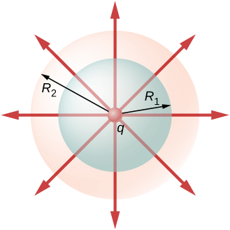
The electric flux exerted on an object outside a spherically symmetric charge distribution is the same as if the charge was just concentrated in the center (it doesn’t matter how exactly the charge is distributed, only the amount)
Likewise, inside the sphere, the exact distribution of charge doesn’t matter, simply the amount of charge enclosed within the distance (just like with gravity)
Thus, E = σR2/ε0r2
R = radius of the sphere
r = distance from the center of the sphere
σ = Q/A → charge density
The E-field at the center of the sphere is 0; increases linearly inside the sphere with radius; maximum at the surface of the sphere, and decreases exponentially outside the sphere with distance
Gauss’s Law in Conductors (Metals)
Metals (Conductors, same thing) have free electrons (so charge can move freely)
Electric field in a metal is 0. Any gaussian surface completely inside a metal has to enclose a net charge of 0. Electric flux through the surface is also 0.
charge can only exist on the surface of a metal
the net charge on the metal and constant and equal to the sum of all the charges on the surface (integral of the surface area)
E-field on a metal is constant, so te=here is no potential difference
Acceleration of charged sphere due to electric field
V = Ed
d = distance
W = ∆K = qV = q(Ed) * ½ mv2
work-energy theorem
E-Field near surface and distance away from a charged sphere
Just use E = kq/r2 → imagine the charge is at a singular point at the center of the sphere
substitute the radius of the sphere for the E-field at the surface; for any distance away, add the radius before substituting into the equation
E-Field along central axis of ring of charge
Components of the electric field perpendicular to the central axis cancel out. and there is only a component along the central axis.
Components parallel to the central axis will be in the same direction and add together. E-field points away from the positive charge, except for the point at the center of the ring where the electric field is zero.
Potential from line of charge
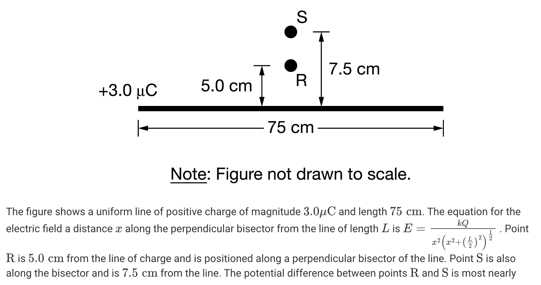
V = - ∫ E dx = kq/L * ln(x+L / x)
∆V = Vs - Vr = 13.5 kV
Basically, integrate across the entire length of the bar; find the equation for V by integrating E dx → then substitute in values for the points
Acceleration of sphere due to electric field and g
a = F/m = qE/m → acceleration due to electric field
acceleration due to gravity → g = 9.8 m/s2
g is vertical and E-fields are horizontal (thus triangle, Pythagorean theorem)
a = √g2 + (qE/m)2
Change in speed due to potential difference
W = ∆K = q∆V = ½ m(vf - vi)2
∆V = change in potential (Vf - Vi)
solve for vf
Current (I)
the rate of charge flow per unit in time through some surface → NOT A VECTOR, even though it has a magnitude and direction
I = dQ/dt → measured in amperes (A)
Conventional Current
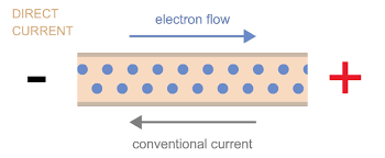
conventional current flows from high to low potential; the electrons actually flow from low to high potential though
Metals have stationary positive ions, and free electrons (negative charge) that move around freely; the movement of the electrons is what allows for current
conventional current is when we treat the positive charge as the moving charge, so it is the opposite of the movement of negative charge
Current Density (J)
it is a vector field in a wire; the vector point at any place in a wire points in the direction of the conventional current
the magnitude of the current would be the current transported in that direction per area of the wire
I = ∫ J dA → current is the flux of current density in a given area

Drift Velocity
even when there isn’t a current through the wire, electrons move at a constant, high velocity; the direction of the velocity is random (which is why the net charge transported is zero)
when current IS flowing in the wire, there is a slight bias as to how the electrons move → they now move with drift velocity
velocity of an electron = ~10-6, n = charge carrier density
Drift speeds are small (10-4 - 10-5) but there are a lot of electrons in a metal, so it can build up and give rise to considerable currents.

Charge Carrier Density, Drift Velocity, and Current Relationship
Charge carrier density is the number of mobile electrons per volume → # of electrons readily available to carry charge. In insulators, n = 0 because they have no free electrons (they don’t allow current to flow)
I = dQ/dt = (neAv0 dt)/dt = neAvD = J * A
J = nevd
e = magnitude of the charge of an electron
A = area
I = JA in a wire with a uniform current
Resistance (R)
it is the potential difference across a resistor
Ohm’s Law: V = IR ←→ R = V/I ←→ I = V/R
R, resistance is measured in ohms (Ω)
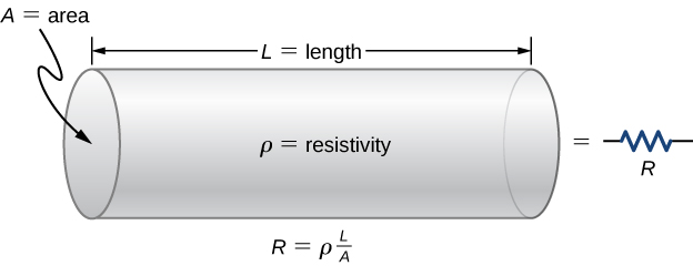
R = ρL / A
L = length of an object; A = area
Ohmic Resistors
They obey Ohm’s law: V = IR → I = V/R
a graph of current as a function of voltage should be a straight line
A graph of current as a function of resistance is curved (1/x = y graph)
maximize the current by minimizing resistance in a closed circuit
Resistivity (ρ)
E = ρJ → ρ = E/J → resistivity is E-field divided by current density
a measure of how strongly an object resists (uses) electrical current
different materials provide more/less resistance; some materials use current better than others (since they allow for the flow of current better/worse)
Resistor
an object that creates resistance in the flow of electric current; Resistors USE current
it reduces the current flowing through a closed circuit
an object with more resistance produces less current as compared to an object with less resistance in the same E-field → more resistance = less current
*NOTE: resistivity is the property of a certain material, while resistance is the property of a particular object
Conductivity (σ)
σ = 1/ρ = J/E
conductivity is the reciprocal of resistivity; they are inversely proportional
conductivity is the ability to conduct charge; the ability to let it pass out of the material; ability to carry’ charge
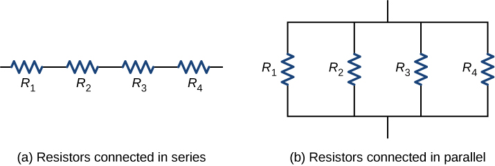
Equivalent Resistance (Resistors in Parallel & Series)
Parallel: 1/Req = 1/R1 + 1/R2 …
Series: Req = R1 + R2 …
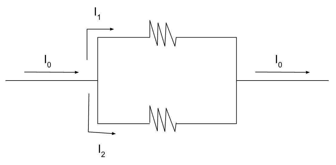
For any closed circuit, Inet = I1 + I2 …
Batteries supply more current to a parallel combination than to a series combination (P = IV, more current = more power)
parallel combinations also have less resistance than series combinations → less resistance = more power too
Analysis of Circuits with a Single Battery
the potential at any point along a continuous stretch of wire (negligible resistance) is constant
at any intersection of wires, the current entering the intersection has to equal the current leaving the intersection
Voltometer
connected in PARALLEL with circuit elements
remember that elements in parallel have the same voltage
measures voltage
has very high resistance so very little current flows through it, thus not disturbing the circuit
With no internal resistance, the reading of the voltmeter will always be the voltage of the battery.
Ampeter
connected in SERIES with circuit elements
elements in series have the same current
measures current (in amperes)
has very low resistance so it doesn’t cause a noticeable change in voltage
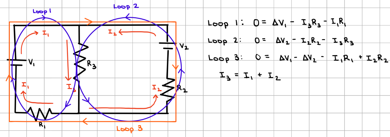
Kirchhoff’s Laws
used to solve complicated circuits with more than one battery (ohm’s law cannot be used here)
Node Rule: at any intersection of wires, the total current entering the intersection must equal the total current leaving the intersection
Loop Rule: the sum of potential differences around any closed loop must be zero
Power (dissipated across a resistor)
Power = change in energy → P = ∆V2/R = I2R
rate of energy transfer to a resistor
Increasing resistance (decreasing current) dissipates more power:
To dissipate twice the power from the same battery, the resistor must have half the resistance → R = ρL / A → either half the length or double the area of the resistor
Internal Resistance
batteries and wires have some resistance irl
voltage across real batteries is the terminal voltage:
Vterminal = EMF - IRinternal
EMF is the ideal voltage of the battery; the voltage of a resistance-free battery
Rinternal is the resistance of the battery
As the current increases, the effect of internal resistance increases, and the actual voltage across the battery decreases: Rinternal = DVterminal / dI
Capacitance
The ability of a capacitor to store charge
capacitors always have plates with equal and opposite charges
C = Q/V = ε0A/d → measured in farads (F)
capacitor plates have opposite charges, so Q is the MAGNITUDE of the charge on the plates
Vcapacitor = - ∫ E dr
limits of integration is the path (distance) between the plates
the plates themselves have constant voltage because they are made of metal
E-field of an infinitely large charged plate: E = σ/2ε0
Equivalent Capacitance (Capacitors in Parallel & Series)
It is the opposite of how you do it for resistors (same as how you add spring constants, k)
Series: 1/Ceq = 1/C1 + 1/C2 …
Parallel: Ceq = C1 + C2 …
Energy Stored in a Capacitor
The energy stored must equal the energy required to charge the capacitor
As you add more charge to the capacitor, the voltage across it increases and it becomes progressively harder to add more charge
U = Q2/2C = ½ CV2 = ½ QV
W = ∫ Q dV → UE = ½ QV
When you add a dielectric, the energy stored decreases by the a factor of kD
Dielectrics
when a dielectric is added to a capacitor, the capacitance increases by a factor of kD (dielectric constant)
C = kDC0 = kDε0A/d (where C0 is the original capacitance)
The electric field between the plates doesn’t change due to a dielectric; only the charge stored increases
Discharging a Capacitor through a Resistor
As a capacitor discharges, the charge across it decreases, and so does the voltage. The charge will eventually be 0 at t = ∞
Q(t) = Q0e-t/RC → charge on a discharging capacitor
Q0 is the initial charge
I = I0e-t/RC → current driven by a discharging capacitor
Charging a Capacitor
At t = 0, there is no charge or voltage across the capacitor. As the capacitor charges, the voltage increases, and it becomes harder to add more charge. Thus, the current decreases with time. At t = ∞, the current will become 0 because the capacitor is fully charged, and holds charge Q = C
Q(t) = Qfinal(1 - e-t/RC)
I(t) = I0e-t/RC → current through a charging capacitor
An infinitely long, thin, nonconducting rod carrying charge −𝑄 is placed inside an infinitely long metal cylinder that has no net charge. The cylinder is not grounded, and the rod does not touch the cylinder. Which of the following describes the distribution of charges on the cylinder?
The inside surface of the cylinder has a charge of +𝑄, and the outside surface has a charge of −𝑄, because the electric field inside the metal cylinder must be zero.
The electric field is zero inside conductors; thus, the electric field is zero inside the metal cylinder. Therefore, the net charge enclosed by any Gaussian surface drawn inside the cylinder must be zero. Since there is a charge of −𝑄 on the rod, there must be a charge of +𝑄 on the inner surface of the cylinder. Also, since the net charge on the cylinder must be zero, there must be a charge of −𝑄 on the outer surface of the cylinder.
Ground sphere and positive test charge → A positive test charge is brought near to, but not touching, a conducting sphere that is connected to the ground. Both objects remain at rest in the positions shown above. Charge begins to flow from the ground to the sphere; when does the charge stops flowing?
the charge no longer flows when the potential is the same everywhere inside the sphere
When the potential is the same everywhere within the sphere, there is no longer an electrostatic force to move the charges on the sphere.
net force on all charges on the surface of the sphere will be zero
Effects of varying Capacitor Plate Separation
The electric field between the plates of the capacitor becomes significantly nonuniform as the value of 𝑑 increases.
Increasing the plate separation (d) will decrease the capacitance. When the capacitor remains connected to the battery, the potential difference (V) will remain the same and the energy stored in the capacitor (UE) will decrease.
Time constant RC circuit
τ = RC
the time taken by the capacitor to be charged to about 63.2% of its full value through a resistor connected to it in series
can also be defined as the time taken by a capacitor connected to a resistor in series to about 36.8% of its full value
Magnetic Field (B)
caused by moving charges → the intrinsic spin of electrons causes magnetic fields in “permanent magnets
B = (µ0 I) / 2πR → measured in teslas (T)
µ0 = vacuum permeability (constant)
I → conventional current; direction of the flow of POSITIVE CHARGE (so if it’s electrons moving, it’s the opposite direction)

Force on a Moving Charge in a Magnetic Field
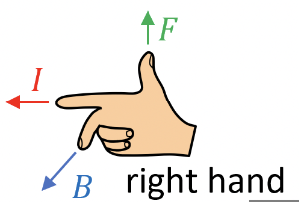
FB = qv * B
B = magnetic field, v = velocity (same direction as current)
A charge must be in motion to feel magnetic force. The magnetic force on a charge at rest is zero
FB on a charge moving parallel or antiparallel to the field is zero
When non-zero, FB is perpendicular to velocity and magnetic field
Magnetic fields only exert force on charged particles
Net force due to FE and FB
Fnet = FE + FM = qE + qvB
Magnetic Field Lines
magnetic field is tangent to the lines
density of the lines is proportional to the strength of the field
field lines never intersect
they point from the north pole to the south pole outside the magnet
there are no magnetic monopoles so the field lines are ALWAYS closed loops
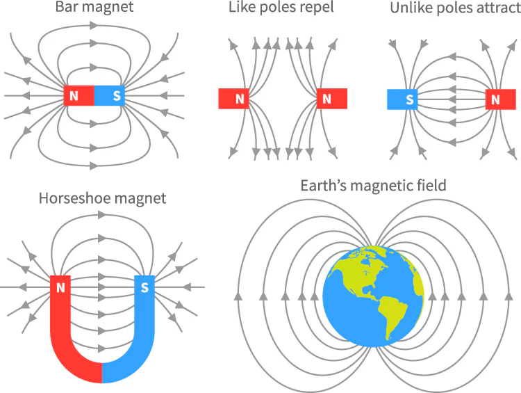
Motion of charged particles in a constant magnetic feild
If a charge moves parallel to the magnetic field, it feels no force. It moves in a straight line
If the charge moves perpendicular to the magnetic field, it experiences a force perpendicular to its velocity → causing uniform circular motion
the strength of the field determines the radius of this motion: mv2/r = q | vB |
If the motion has components both parallel and perpendicular to the field, the charge will experience constant velocity parallel to the field and move in uniform circular motion in the plane perpendicular to the field (net result → helical/corkscrew path through space)
Path (radius) of Ions in a magnetic field
If the ion is moving perpendicular to the field, causing uniform circular motion
work done by the potential difference (qV) is equal to the KE gained by the particles (1/2 mv2) → qV = ½ mv2 → v = √2qV/m
Set the magnetic force equal to the centripetal force: qvB = mv2/r
solving for the radius, r = 1/B √2mV/q
as mass increases, so does radius
as charge increases, radius decreases
as the strength of the field increase, radius decreases
FB on Wires
FB = I * length * B * sinθ → FB of a straight current carrying wire in a constant magnetic field
if the wire has no net current, the net force is also zero → random motion of electrons does not raise a net force for the same reason it doesn’t raise a net current
net force in a wire is equal to the sum of FB on all the electrons moving in the field
FB = e(NvD) * B
vD = drift velocity
N = n * length * Area → n = volume density of electrons
dF = Id(length) * B → FB on a differential length, d(length) of a current-carrying wire (curved wires)
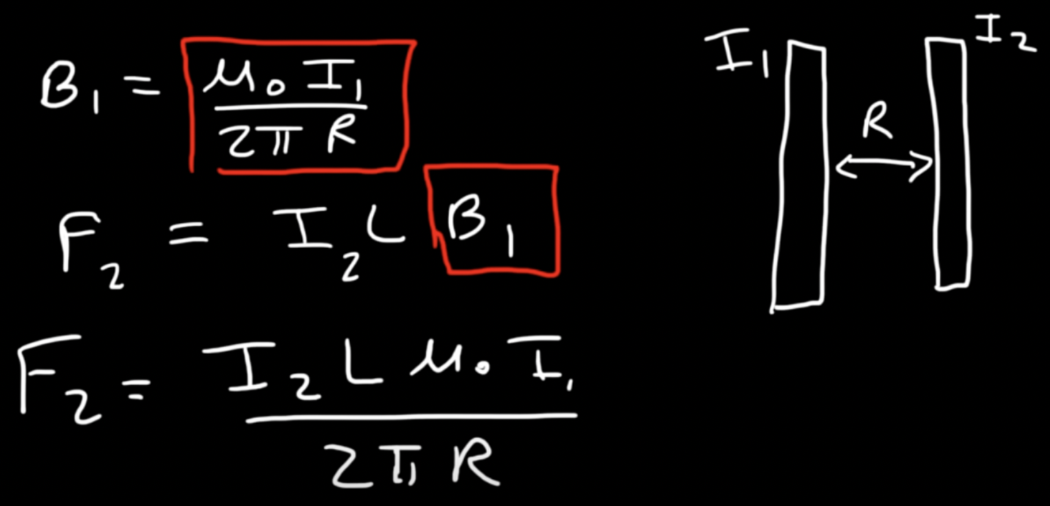
Magnetic Forces between Wires
F2 = I2 * I1Lµ0 / 2πR
two wires parallel to each other with currents running in the same direction attract each other
two wires parallel to each other with currents running in opposite directions repel each other
The magnetic field between parallel wires with opposite currents is in the same direction
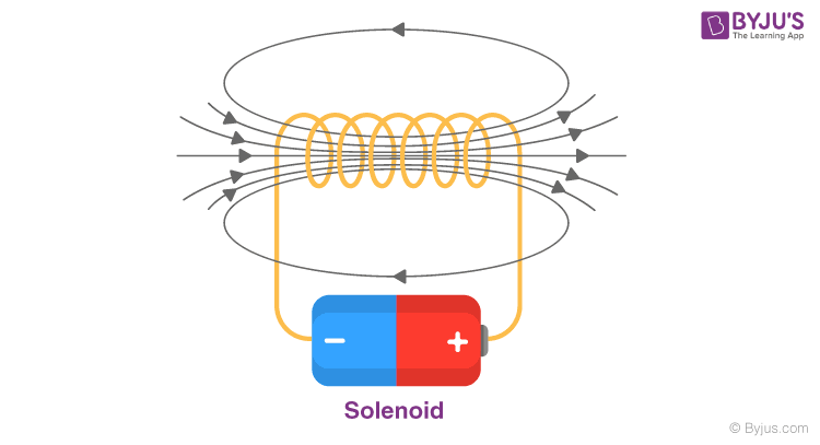
Solenoid
The magnetic field in the center of the wire is very strong; adding loops increases the strength inside the wire
outside the loop, the magnetic field is weak
when 10 amperes go through one loop, and the current of the solenoid is 10 A. But as the loops increase, the current through the solenoid increases as well → 2 loops = 20 A, 3 loops = 30 A, etc.
Bsolenoid = µ0In
n = # of loops / length of solenoid → turns per meter
Increasing # of turns, decreasing length, or increasing current all increase the magnetic field
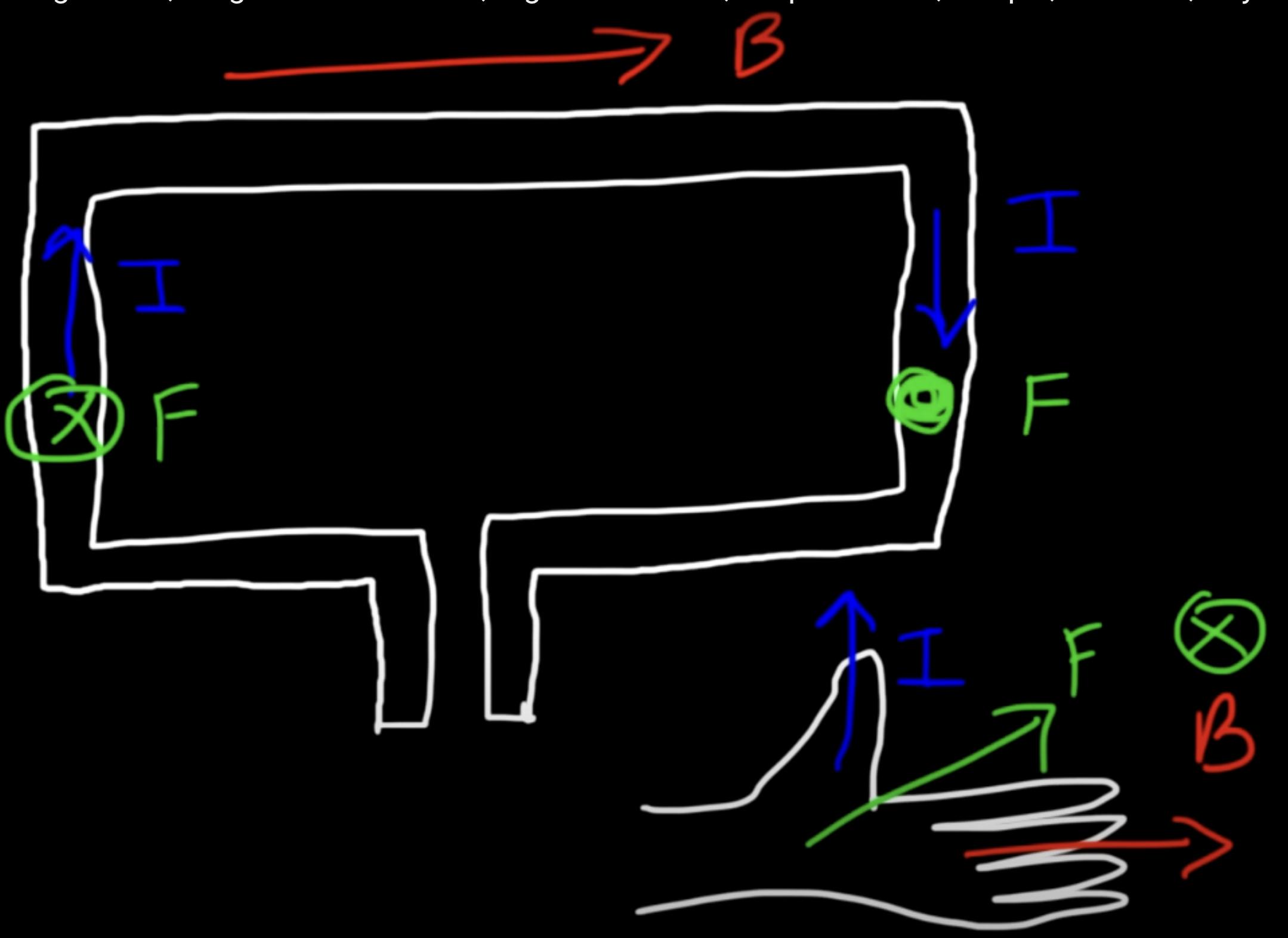
Torque on a Wire Loop
(sections of the loop where the current is parallel to the field → no torque because no force)
Note: F = I * L * B
torque = MB * sinθ
Magnetic Dipole Moment (M) = NIA
N = # of loops/length of solenoid
A = Area (of the loop)
The loop will rotate because the magnetic force on two sides of the loop (which are perpendicular to the magnetic field) is in opposite directions
Forces on Wires in Uniform Magnetic Fields
FB = ∫ I dL * B
dL = net displacement of the wire, so if it is a closed loop, the net displacement is 0 and the magnetic force is 0
Mass Spectrometer Problems
charged particles are accelerated when passing through the parallel plate capacitor; they gain kinetic energy equal to qV
qV = mv2/2 → KE gained by passing through a capacitor
E-field in a parallel plate capacitor: V = Ed
When FE ≠ FM, there is a net force on the particle and it will NOT move in a straight line through the capacitor (will be attracted to one plate). When FE = FM, there is no net force & the particle will travel in a straight line through the capacitor
Biot-Savart Law
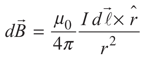
magnetic field due to the differential length of a wire
dB = (Iµ0/4πr2) dL * r̂
r̂ is a vector; distance
magnetic field will increase if there is more current, if the wire is closer to the point of interest, or if r̂ is more perpendicular to the dL
Ampere’s Law
∫ B dI = µ0Ienclosed
Like Gauss’s Law, calculates the magnetic field due to current distributions w/ particular symmetries (thus no need for Biot-Savart)
it is a restatement of biot-savart
only valid when E-field is present as well
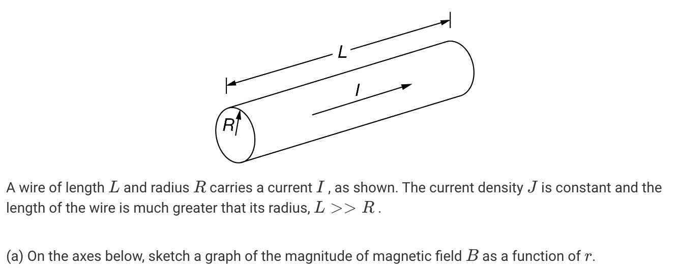
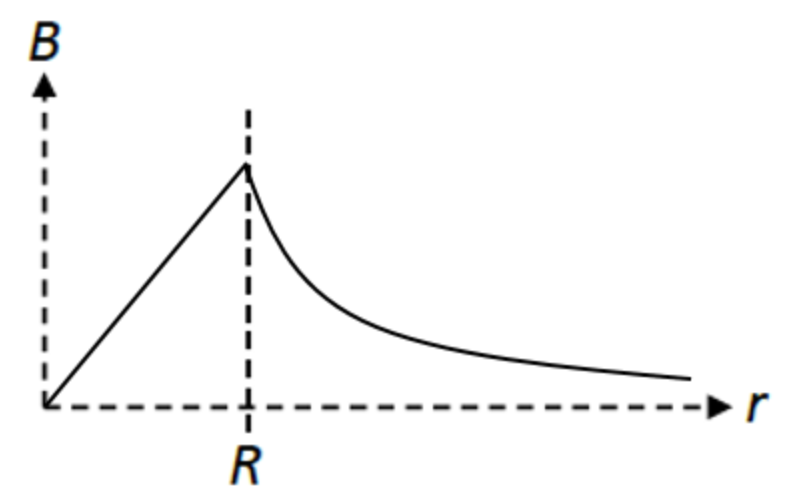
Graph the magnetic field of a wire with respect to distance
just like with the gravity in a solid sphere, or E-field in a charged sphere, increases linearly until the surface, decreases non-linearly after
Which of the following could be true for a Gaussian surface through which the net flux is zero?
I. There are no charges inside the surface.
II. The net charge enclosed by the surface is zero.
III. The electric field is zero everywhere on the surface.
All three
Magnetic Flux
ΦB = BA cosθ (Units: Wb)
induced current/emf depends on the rate of change of flux
ε = -N∆ΦB/∆t → induced emf = # of coils * rate of change of magnetic flux
ε = IR = BLv
Inducing Current in a Coil with a Magnet
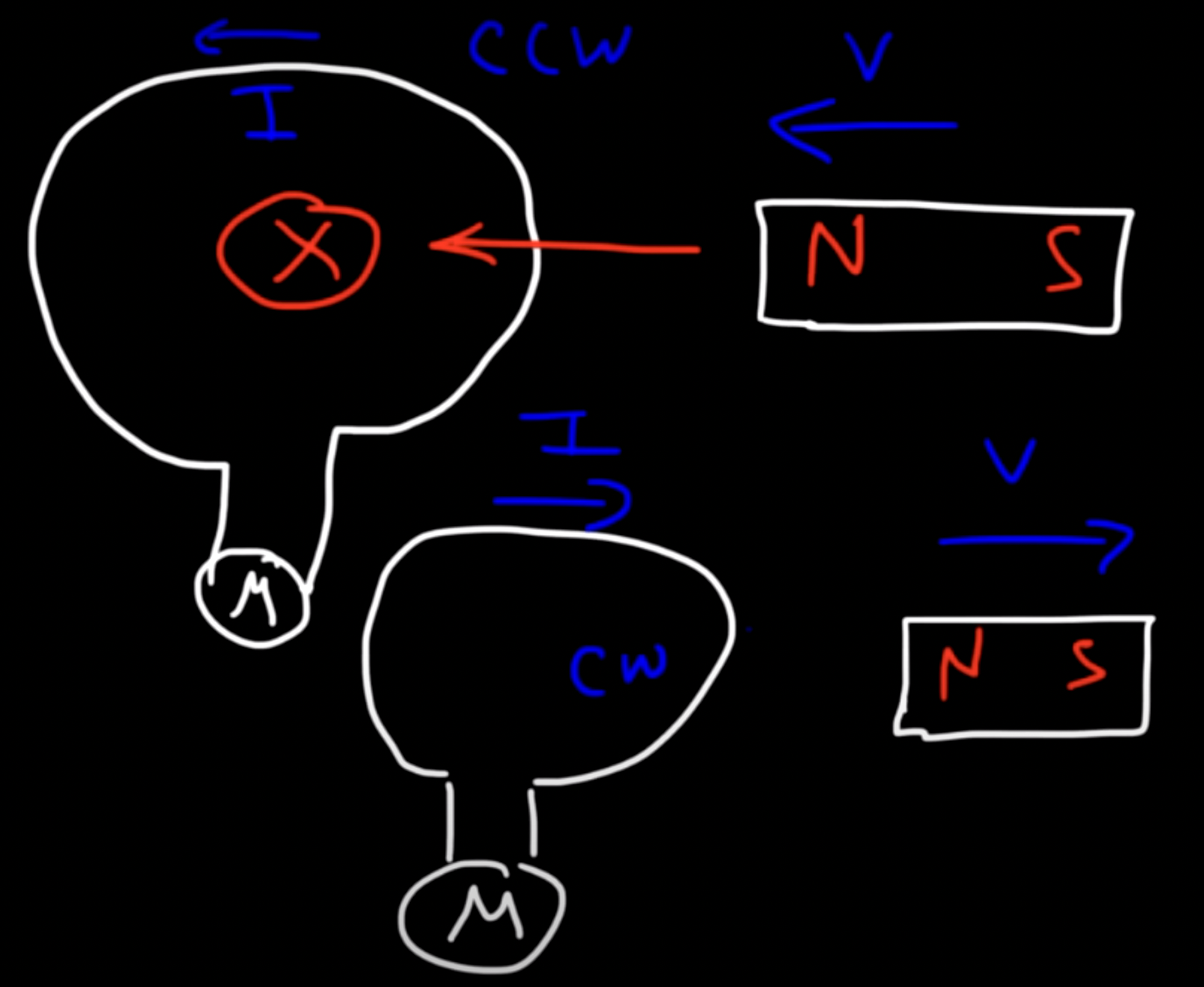
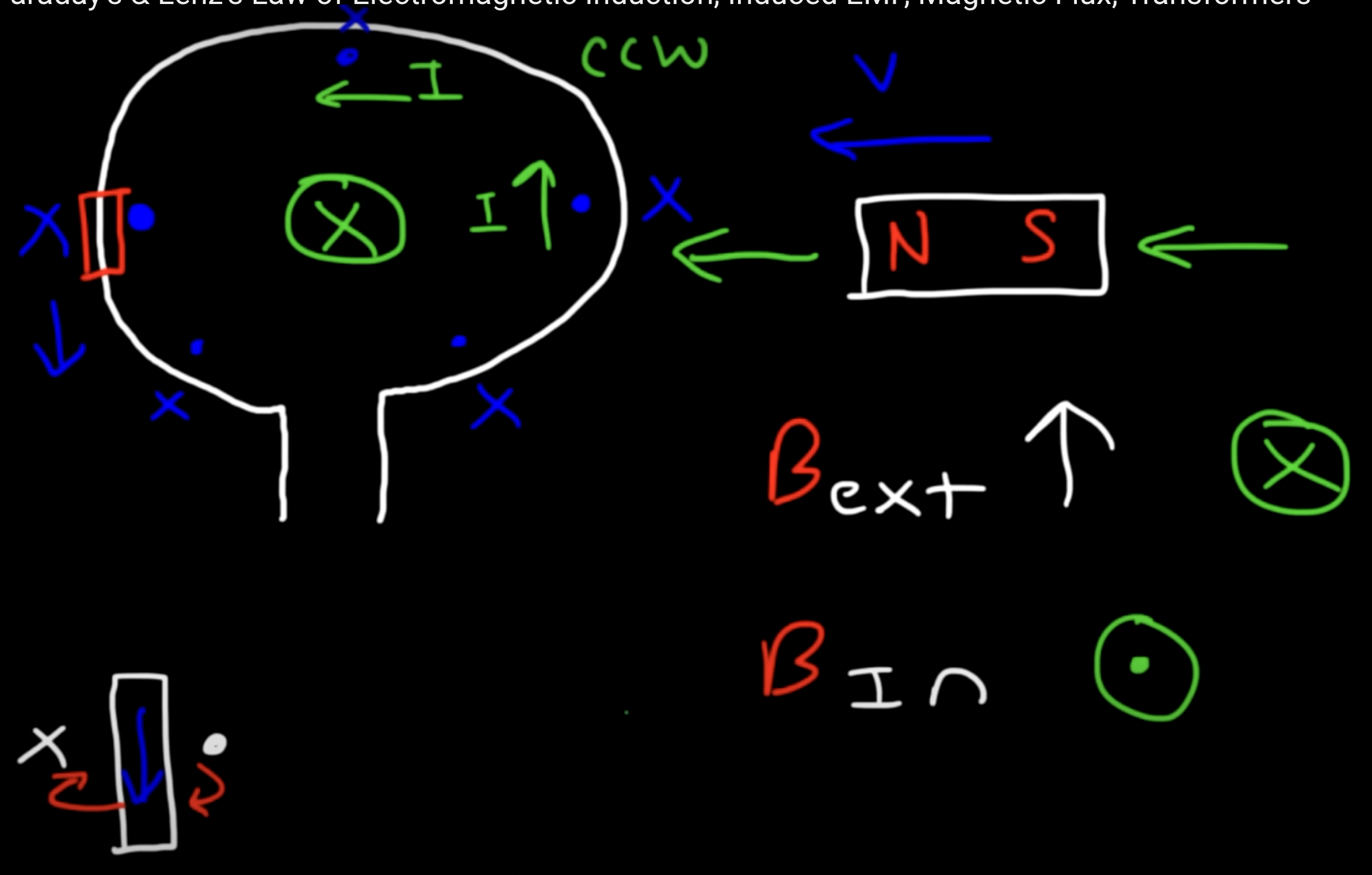
If you move a magnet into a coil, the current will be counter-clockwise
If you move a magnet away from the coil, the current reverses and becomes clockwise
If you move the magnet into the coil slowly, the induced current is very small; move the magnet in quickly and the induced current is large
Stretching/bending the coil or changing the angle relative to the magnetic field also induces current in the coil/wire
Lenz's Law
Induced emf always gives rise to a current whose magnetic field opposes the original change in flux
If the external magnetic field is increasing, magnetic flux increases too; if flux increases, induced current is directed in a way that will decrease flux
B increases, induced current decreases; B decreases, induced current increases → they are always opposite
figure out if flux increases/decreases by considering area, angle, and magnetic field; ex. if you are moving a coil into a constant magnetic field, the flux increases (cuz area exposed to B increases)
induced current directed opposite to the magnetic field decreases flux; if I and B are in the same direction, flux increases
Inductance (L)
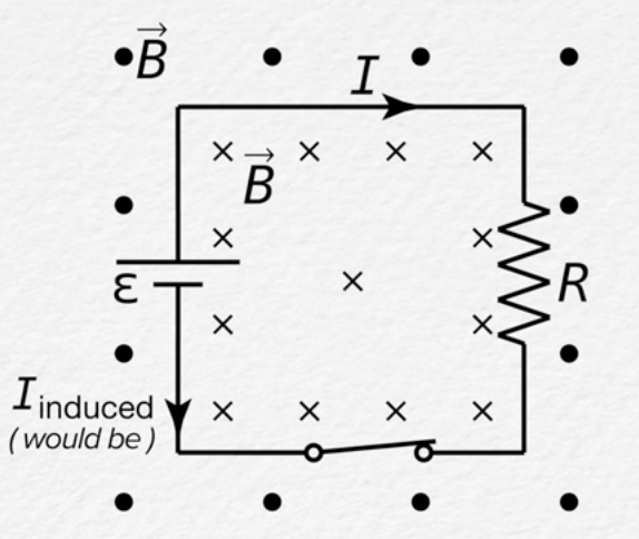
If there’s a circuit with a switch, closing the switch creates a closed loop and the circuit will have current I. However, it takes time for I to exist. Closing the loop, creating I… increases magnetic flux, so there is induced current in the circuit that acts against I → thats why it takes time → SELF INDUCTANCE
Inductance is the resistance to the change in current in a circuit
εL = -L dI/dt
Inductance of A solenoid
Lsolenoid = NΦB/I = BNA/I = µ0N2A/L
Energy Stored in an Inductor
P = Iε = rate at which energy is added to the circuit battery
P = LI * dI/dt = rate at which energy is being stored in the B-field of the inductor
UL = ½ LI2
energy is only present when the charge is moving through the conductor (there is a current)
Note: In a capacitor, the potential difference is stored in an E-field. In an inductor, it is stored in a B-field
LR Circuit (has inductors)
The electric potential difference across an inductor goes down (like with resistors) because it is being stored in the B-field of the inductor
After a long time, the current in the circuit remains constant, so the circuit acts as if the inductor was not there
(dI/dt)initial = ε/L
If = ε/R
I(t) = ε/R * (1 - e-Rt/L)
Imax = (1 - e-Rt/L)
Time constant for an LR circuit
τ = L/R
LC Circuits
there is potential difference across the capacitor plates, but no current in the circuit as long as the switch is open
even after the switch is closed, LC circuits don’t reach a steady state
As current through the inductor increases, charge stored in the capacitor decreases → E-field magnitude in the capacitor decreases as B-field in the inductor increases
eventually charge on the capacitor will be 0, B-field and current are max; but then current flows into the capacitor again (but the positive/negative plates are reversed this time), and capacitor charges again → process repeats in reverse
its like simple harmonic motion… 😋
I(t) = (Qmax /√LC)(sin t/√LC)
Imax = Qmax/√LC