AOP-501 (2) Loss of Main Control Room Air Conditioning
1/16
There's no tags or description
Looks like no tags are added yet.
Name | Mastery | Learn | Test | Matching | Spaced | Call with Kai |
|---|
No analytics yet
Send a link to your students to track their progress
17 Terms
Entry Conditions
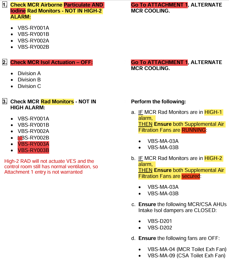
Particulate and Iodine Alarms (High-2)
Radiation (Gaseous) Alarm
(Steps 1-3)
Notice: “Go To” therefore Main Body of A-501 is NOT continued concurrently until Attachment 1 is completed
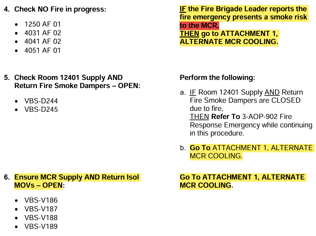
Fire in Progress
Smoke Dampers
Main Control Room Supply/Return Isolation MOVs
(Steps 4-6)
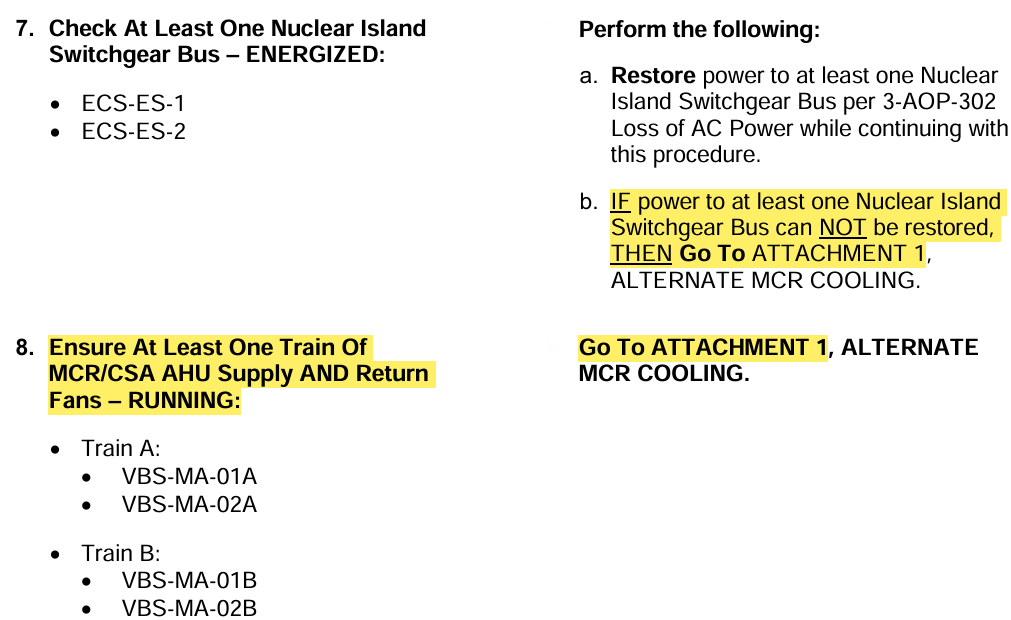
Nuclear Island Switchgears
MCR/CSA AHUs
(Steps 7 & 8)
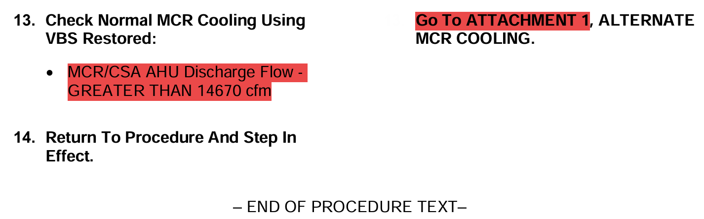
VBS Normal MCR Cooling Flow Requirement
(Step 13)
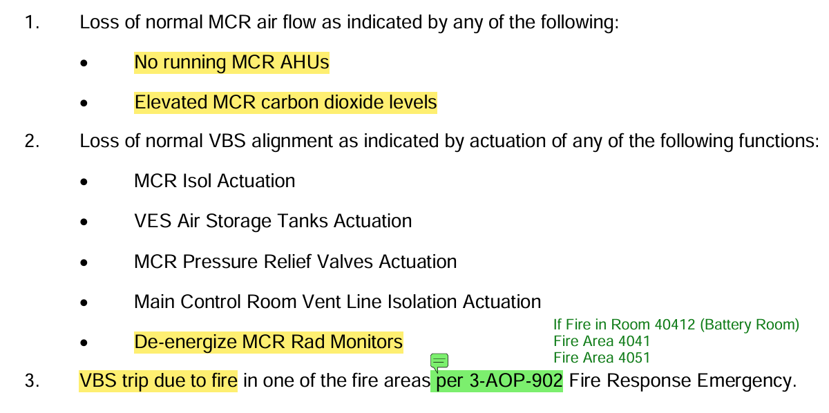
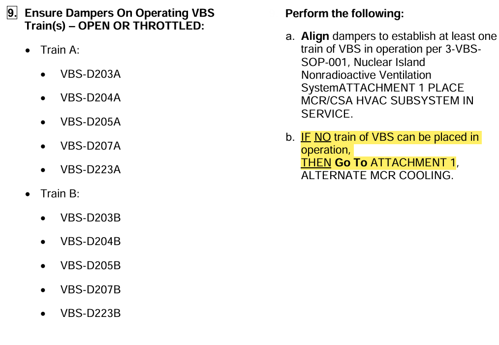
VBS Failure
(Step 9)
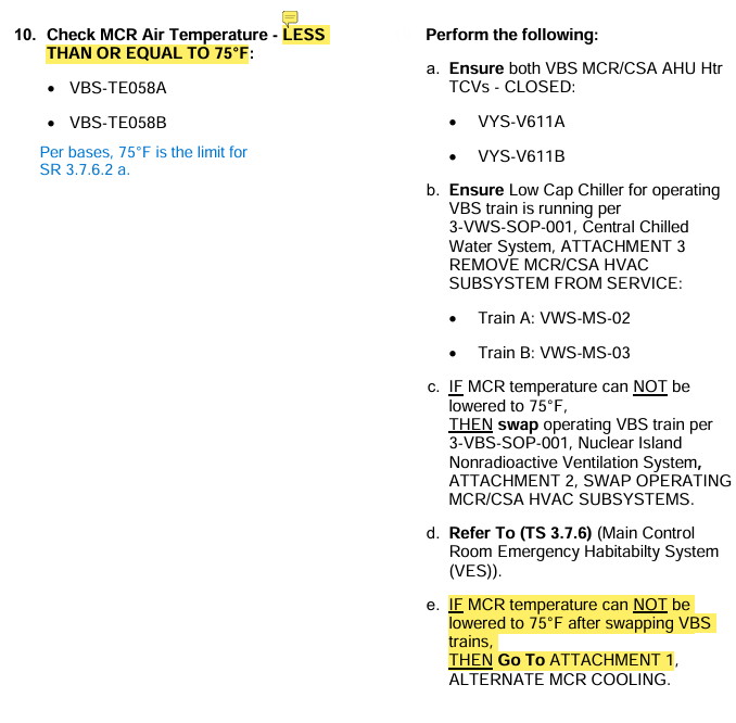
Main Control Room Temperature
(Step 10)
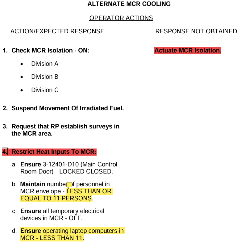
Attachment 1 Alternate MCR Cooling
VES Actuation
Fuel Movement
Heat Input Restrictions
(Att. 1 Steps 1-4)
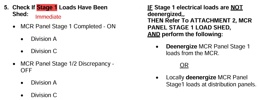
Stage 1 Load Shed
(Att. 1 Step 5)
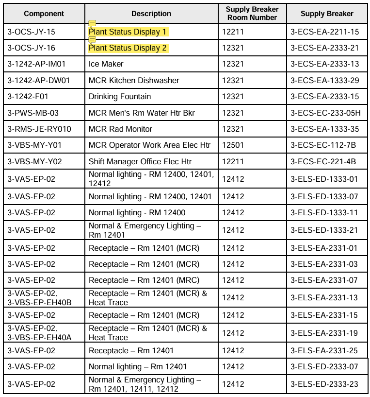
Stage 1 Load Shed List
(Attachment 2)
Notice:
Plant Status Display 1 & 2 are “WPIS” 15 & 16
Not pictured:
Main Control Area Conference Table breakers
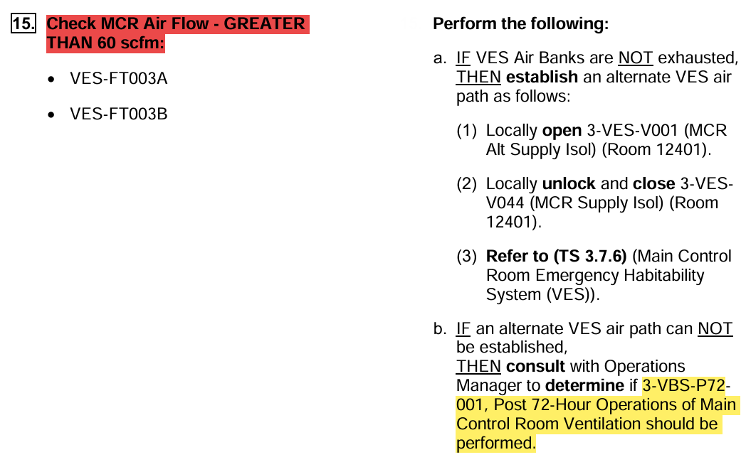
VES MCR Supply SOV Failures (VES-V005A/B)
(Att. 1 Step 10)
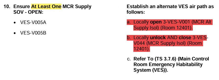
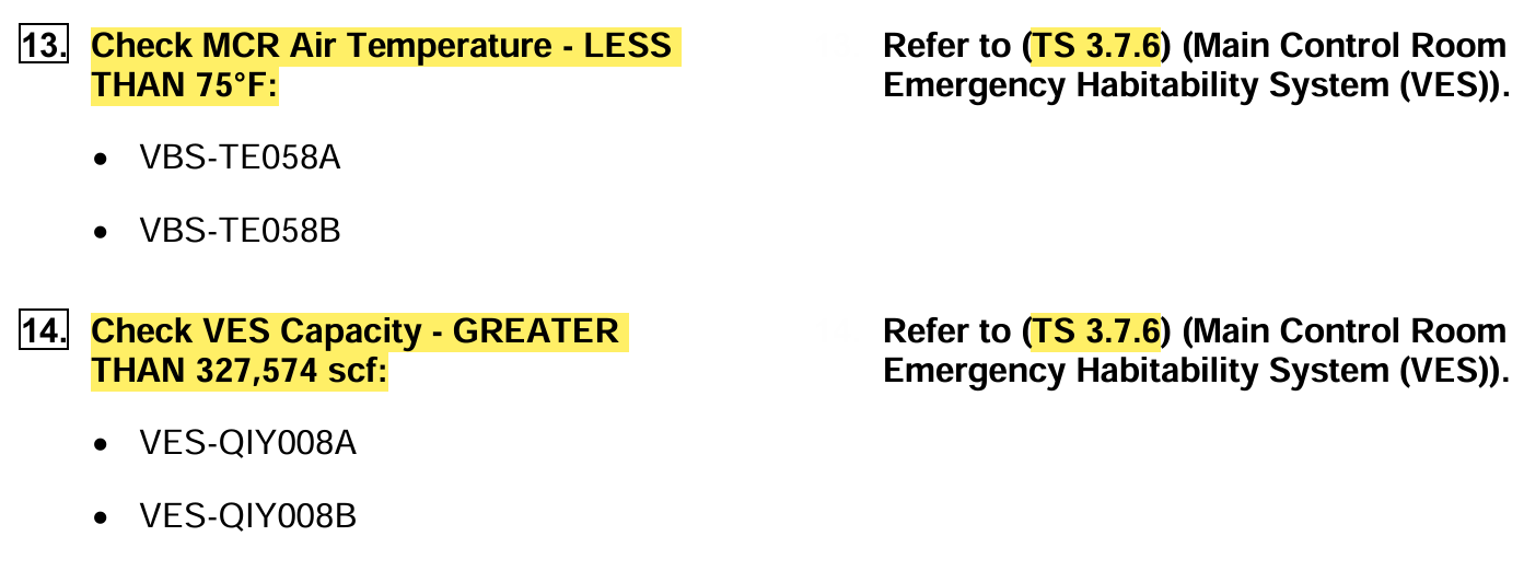
LCO 3.7.6 Main Control Room Emergency Habitability System (VES)
Temperature
Capacity
(Att. 1 Steps 13 & 14)
Note:
Spaces adjacent to MCR are required to be <85°F to satisfy 3.7.6
VES Flow Requirement
(Att. 1 Step 15)
Stage 2 Load Shed
(Att. 1 Step 17)
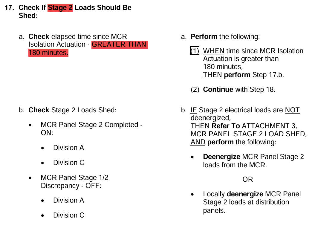
Stage 2 Load Shed List
(Attachment 3)
Notice:
“Reactor Operator Consoles” are the LAN computers, NOT the IDS-Powered Control Stations used to manipulate PLS
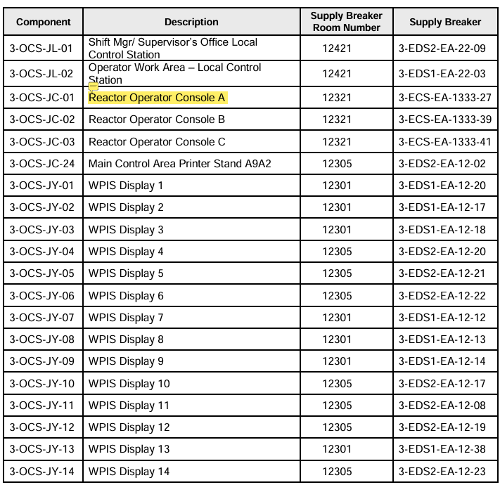
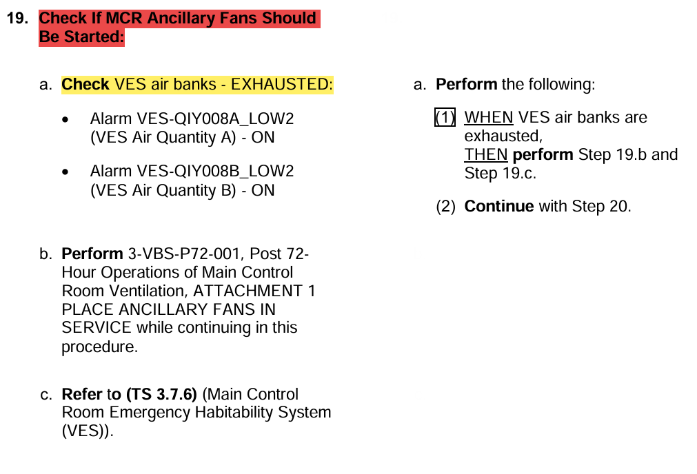
MCR Ancillary Fans
(Att. 1 Step 19)
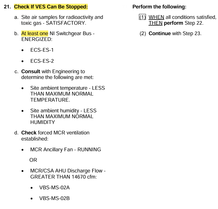
Criteria to Stop VES
(Att. 1 Step 21)