1300
1/49
There's no tags or description
Looks like no tags are added yet.
Name | Mastery | Learn | Test | Matching | Spaced | Call with Kai |
|---|
No analytics yet
Send a link to your students to track their progress
50 Terms
Current is
dQ/dt - the rate of flow of charge
Formula for Power (P)
P = V * I = dW/dt
On a diagram, you would draw the current moving
in the flow of the positive charge if they could move, or basically opposite way to the electrons when they’re moving
Kirchoff’s Voltage Law
The sum of Voltage Rises = The sum of Voltage drops
Kirchoff’s Current Law
The sum of current in a node = the sum of current out a node
If voltage and Current arrow are in the same direction
There is negative power —> meaningn supplying power
If voltage and current arrows are in the opposite directions
There is positive power —> power is being dissipated/used
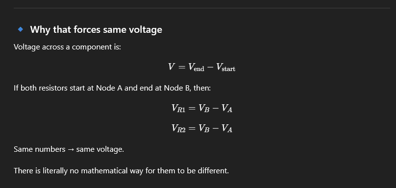
Vbranch = Vy - Vx
where Vy and Vx are nodes
All points connected by a plain wire have the same voltage.

In series, voltage splits across resistors because the same current passes through different resistances, so each resistor uses up a different portion of the total voltage.
current always flows from high voltage to low voltage
nodes are the points where components join, not every corner of the drawing.
For series, Components share one node that only connects those two components (no branching at that point).
For parallel, Both components connect to the same two nodes.
To find Thevenin Resistance
Disconnect all sources and then calculate the resistance looking into the output port
To find Thevenin Voltage
Find voltage across the same node thing, and you can disregard the resistors that are connecting to the output/load line becaues there is no current flowing through them.
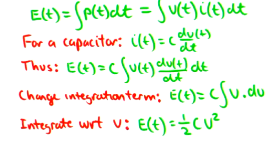
Formula for Energy stored in a capacitor
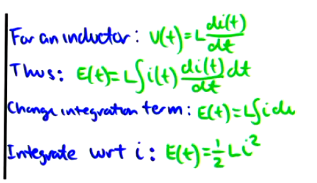
Formula for Energy stored in an inductor
When to use Nodal Analysis
Use when:
Lots of parallel branches
Many current sources
When to use Mesh analysis
se when:
Circuit is mostly series loops
Mostly voltage sources
Planar circuit (no weird crossing wires)
Superposition
Use when:
Multiple independent sources
You only need one voltage or current
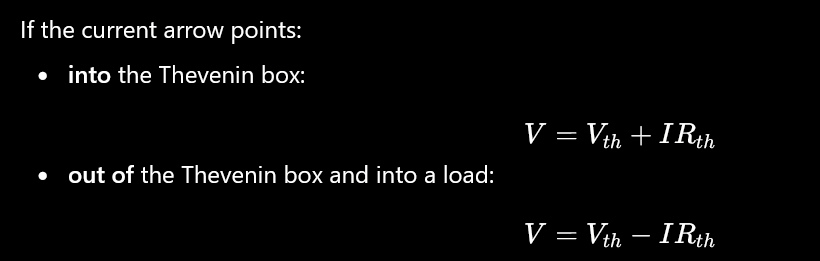
Thevenin Equivalent
V = Vth - I(Rth)
This is when I is leaving the port
A parallel combination is always less than the smallest resistance in that specific parallel group
when you have two current sources in a circuit
use mesh, loko at 2023 exam
Difference between when tryna find Thevenin voltage and I norton when you have either voltage or current source
Thevenin = “What voltage appears if nothing is connected?”
Norton = “What current flows if I directly connect the terminals?”
So yes — when finding Norton current, you are literally doing the opposite of Thevenin:
🔄 Open circuit ↔ Short circuit
What are the units for capacitors and inductors
Capacitors = Farads
Inductors = Henries
A practical capacitor does not allow an instantaneous step change in its:
No instantaneous change in voltage
No instantaneous change in electric field
A practical inductor does not allow an instantaneous step change in its:
No instantaneous change in current
No instantaneous change in magnetic field
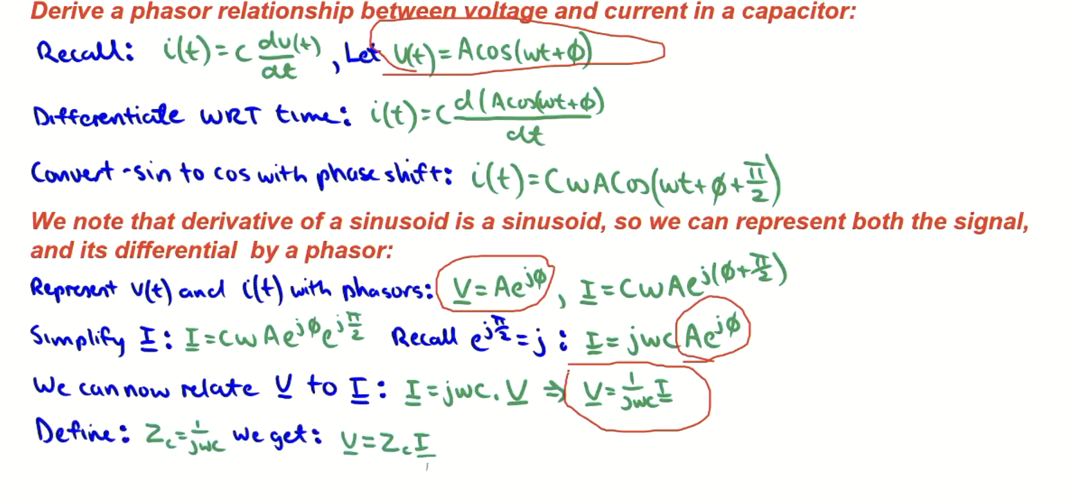
capacitor - component law for phasors
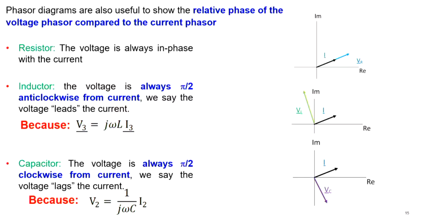
Phasor Diagram interpretations
Resistor: The voltage is always in phase with current
Inductor: the voltage is always pi/2 anticlockwise from current, we say that voltage “leads” current
Capacitor: The voltage is always pi/2 clockwise from current, we say that current “leads” voltage
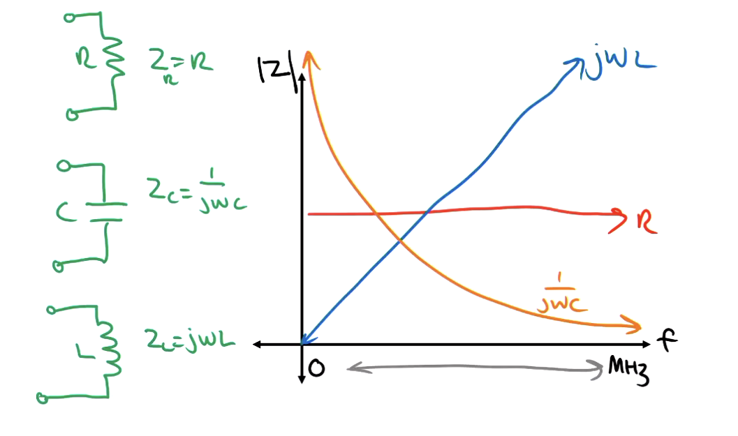
If you increase the frequency for a capacitor /inductor
The impedance decreases and approaches 0, and if you have very low frequency it approaches infinity
Opposite away around for an inductor
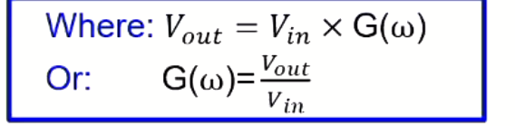
What is a transfer function
A transfer function doesn’t “do” anything physically — it describes how the circuit transforms signals.
It tells you:
How much the signal is amplified or attenuated
Whether it is inverted
How it behaves with frequency (e.g. filters)
For example:
If H=10H = 10H=10, output is 10× bigger → amplifier behaviour
Transfer function formula
Gain(db) formula

An inductor consumes positive VARs
A capacitor consumes negative VARs
VARs consumed = VARs supplied
Qave is positive if reactive load is positive, i.e reactive part of the load is inductive
Qave is negative if reactive load is negative, i.e react part of the load is capacitive
there will be a short answer written question about power, communication and control systems
best past exam papers: 2017 sem 2, 2019, sem 1 2021, sem 1 2024
X>0 (inductive) → current lags (positive ϕ\phiϕ)
X<0X < 0X<0 (capacitive) → current leads (negative ϕ\phiϕ)
explain why electrical power is transmitted over long distances at very high voltages (i.e. 275KV), even though it is generated and utilised at much lower voltages?
Increasing the voltage using a transformer decreases the current by the same factor, thereby minimising I²R power losses in the transmission line
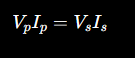
for Transformer
Vp/Vs = Np/Ns
Bang Bang control
Bang-bang control switches between two extreme states only: fully on or fully off
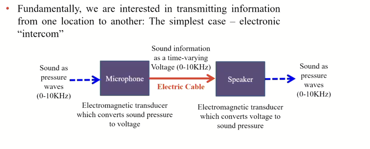
demodulation in AM (amplitude modulated) radio singals
converting a varying high-frequency wave back into the original low-frequency message by extracting its amplitude envelope.
to identify band pass or band stop
series across V out is band stop
Parralel across V out is band pass
if inductor and capacitor are in series - band stop
if inductor and capacitor are in parallel - band pass
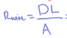
formula for resistance in a wire
Briefly (in a sentence or two) explain why electrical power is transmitted over long distances at very high voltages (i.e. 275KV), even though it is generated and utilised at much lower voltage
lossess in transmission lines is proportional to I²
transmitting at very high voltages minimises I (for a given power delivery) and therefore minimises transmission line losses
proportional control in context of car cruise control
driver sets desired speed
spedometer measures acutal speed
the error (difference in speed) is calculated and throttle is set proportionally to current error, i.e throttle setting adjustment is proportional to error.
energy = V * I multiply (time)
In a sentence or two, describe a practical example of an electronic filter that is used to remove noise from an electronic signal of interest. You should explicitly state the filter type and the describe the frequency characteristics of the noise that is removed and the signal that is preserved.
In an AM radioreciever a band pass filter is used to slect the desircd radiochanne
op amp formula for inverting
-Rf/Rin
op amp formukla for non inverting
1 + Rf/Rin