Paper 1 - Unit 4 - Processor fundamentals
1/71
There's no tags or description
Looks like no tags are added yet.
Name | Mastery | Learn | Test | Matching | Spaced | Call with Kai |
|---|
No analytics yet
Send a link to your students to track their progress
72 Terms
FDE cycle
Fetch - The next instruction is fetched from memory (RAM)
Decode - The instruction is interpreted so that it can be carried out
Execute - The instruction is carried out by the CPU
Von Neumann architecture
Computer programs and the data the programs are using are stored in the same memory.
Stored program concept
Stored program concept
program must be resident in (main) memory to be executed
program consists of a sequence of instructions...
...which occupy a (contiguous) block of main memory
instructions and data are indistinguishable
each instruction is fetched, (decoded) and then executed
instruction fetch and data operation cannot occur at the same time
Clock speed
Number of cycles the CPU can execute per second
Each instruction is executed on a clock pulse
Increasing clock speed increases the number of operations/number of fetch-execute cycles that can be carried out per second
However, there is a limit on clock speed because the heat generated by higher clock speeds
Cores
Each core processes one instruction per clock pulse
More/multiple cores mean that sequences of instructions can be split between them
... more sequences of instructions can be run at the same time
More cores decreases the time taken to complete task
Cache
A tiny block of memory built right onto the processor.
Stores the most commonly used instructions and data are stored in the cache so that they are close at hand and so it does not need to travel back to RAM so often
L1, L2, and L3 caches serve different roles, with L1 being the fastest but smallest, and L3 being larger but slower.
Bus width
Determines the number of bits that can be simultaneously transferred
Increasing the width of the data bus increases the number of bits/amount of data that can be moved at one time (or equivalent)
Hence improving processing speed as fewer transfers are needed
e.g. double the width of the data bus moves 2x data per clock pulse
Control Unit
Coordinates all of the activities taking place within the CPU
It tells the computer's memory, arithmetic/logic unit and input and output devices how to respond to a program's instructions.
Each step is synchronised with a regular pulse from the system clock
CPU Registers
• Small piece / word of (fast) memory
• Part of the processor
• Temporary storage of data
• Data is about to be / has been processed
Arithmetic Logic Unit
Performs arithmetic computations and logical operations.
Accumulator
A storage register in the ALU that holds data temporarily while the data is processed and before it is transferred to memory.
Program Counter (PC)
The register that contains the address of the next instruction to be fetched from main memory
The address in the Program Counter (PC) is copied to the Memory Address Register (MAR)
The Program Counter (PC) is incremented
Memory Address Register (MAR)
Either stores the memory address where data will be fetched from the CPU, or the address to which data will be sent and stored
Instructions are copied to the Memory Data Register (MDR) from the address held in the Memory Address Register (MAR)
Memory Data Register (MDR)
A register that stores the data being read from or written to main memory RAM.
This could be data to be processed, or an instruction being fetched.
Current Instruction Register (CIR)
A register inside the CPU which holds the current instruction (not the data) being executed before it is passed to the control unit to be decoded
Status Register (SR)
Holds condition flags/independent bits.
Each flag is set depending on an event.
For example, an arithmetic operation may produce a positive, negative, zero or overflow result, so a flag is set accordingly.
Also status information, such as whether interrupts are enabled or disabled
Stages in the von Neumann fetch-execute cycle
1. The address contained in the Program Counter (PC) is copied to the Memory Address Register (MAR)
2. PC is incremented by 1
3. The instruction is copied from the memory location contained in the Memory Address Register (MAR).and is placed in the Memory Data Register (MDR)
4. The instruction is copied from the Memory Data Register (MDR) and placed in the Current Instruction Register (CIR)
5. The instruction in CIR is decoded by the Control Unit
6. If additional data is required then it is fetched from memory
7. The instruction is executed using the ALU. Registers are used to store intermediate data.
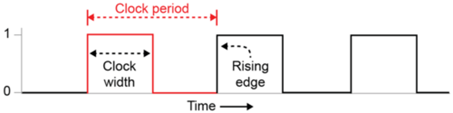
System clock
Generates the signals to synchronise events in the processor's fetch-(decode)-execute cycle
A series of regular ON/OFF timing signals are used to synchronise the operations of the processor components (actions are usually carried out on the rising edge of the clock).
System clock can be used to keep track of date and time/timestamp files.
System clock used in order to process operations in the correct order/sequence.
Index Register
- Used in indexed addressing
- Stores a number used to modify the address (in address field)
- Provides an efficient way to access a number of consecutive locations
- Used for arrays
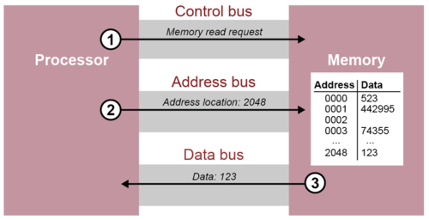
Bus
Consists of a series of wires that transfer data signals between internal components
They typically consist of 8, 16, 32 or 64 lines
Control Bus
Used to transmit control signals
e.g. read/write/fetch/
Dedicated bus since all timing signals are generated according to control signal.
Address bus
Lines used to transfer address of memory or input/output location
Unidirectional bus
Width of the address bus determines the maximum possible memory addresses of the system
A 32-bit bus can carry 232 (4GiB) addresses
Data bus
Used to transfer data between the processor and memory/input and output devices
The width of the data bus is defined by the number of wires or lines it contains
Bus width affects overall system performance
Bi-directional bus
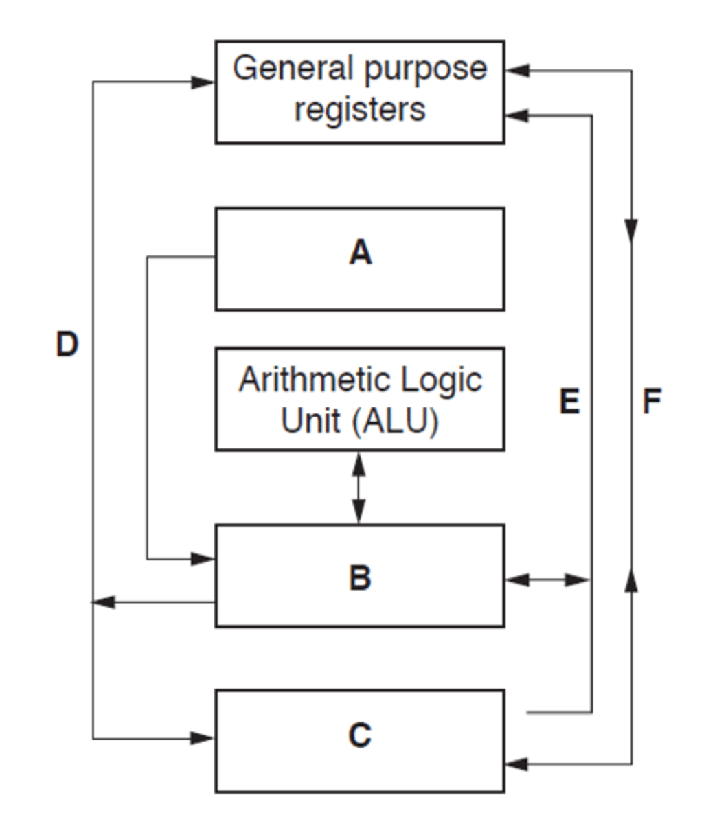
Labelling a CPU example
A - System clock
B - Control unit
C - Main memory - All buses interact
D- Address bus - should be shown as uni-directional
E - Control bus
F - Data bus - bi-directional
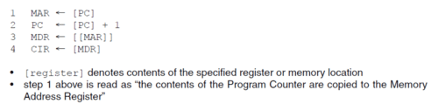
Register transfer notation
Notation used to describe the transfers between registers
[register] denotes contents of the specified register or memory location
Step 1 is read as "the contents of the Program Counter are copied to the Memory Address Register"
Double brackets means the data stored at the address held in MAR is copied into the MDR
![<p>Notation used to describe the transfers between registers</p><p>[register] denotes contents of the specified register or memory location</p><p>Step 1 is read as "the contents of the Program Counter are copied to the Memory Address Register"</p><p>Double brackets means the data stored at the address held in MAR is copied into the MDR</p>](https://knowt-user-attachments.s3.amazonaws.com/e8466601-0dac-4b6c-afd0-a8fa9c9805c2.png)
Register transfer notation example
Step 1 is read as "the contents of the Program Counter are copied to the Memory Address Register"
the program counter is incremented
(the data stored at the address held in MAR is copied into the MDR
the contents of the Memory Data Register is copied into the Current Instruction Register
Interrupts
Signals sent to the CPU by a program/device to indicate an event that needs immediate attention by the CPU
They tell the CPU to suspend its current activities and execute appropriate instructions
Hardware interrupts are generated by hardware devices
Software interrupts are generated by programs, e.g. a divide-by-zero error will cause a calculation to be abandoned and an error message displayed
Actions of the processor when an interrupt is detected
1. At a point during the fetch-execute cycle ...
2. Check for interrupt
3. If an interrupt flag is set in interrupt register
4. All contents of registers are saved into a register
5. PC loaded with address of interrupt service routine
6. when the ISR completes, the processor restores the register contents.
Interrupt examples
External events
Key press
Mouse movement
Errors:
Can be triggered in case of errors or exceptional conditions, such as division by zero or memory access violations.
Timer Events:
A timer interrupt is often used for time-sensitive tasks, allowing the operating system to perform periodic actions like updating the system clock or managing time-dependent processes.
Instruction set
Describes the commands a processor can perform
Different types of processors have their own instruction sets but they may perform similar or identical operations
Each instruction has a unique machine code equivalent, for example a very basic processor might hold each instruction in a single byte
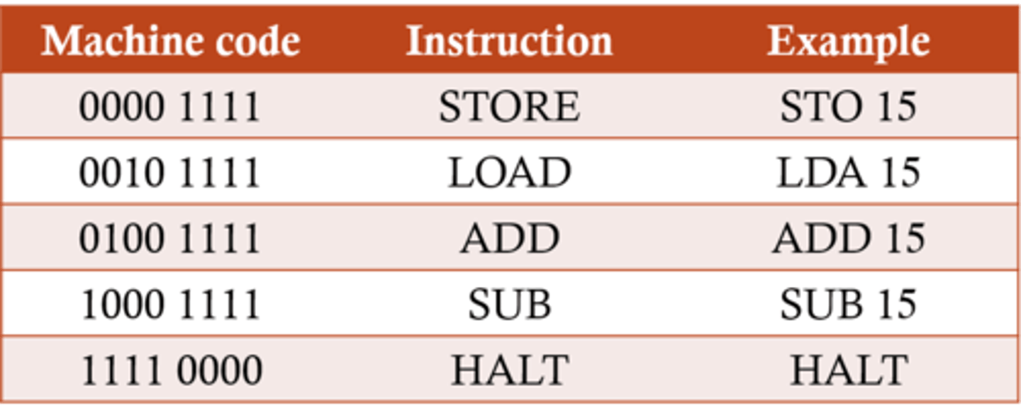
Types/Categories of instructions(Assembly)
Data Movement such as LOAD, STORE
Input and Output instructions such as IN, OUT
Arithmetic operations such as ADD, SUBTRACT
Compare operations to compare two values such as CMP, CMI
Conditional and unconditional Instructions - branching/jump such as JMP, JPE, JPN
Logical operations such as AND, OR, NOT
Shift operations - shift bits left or right in a register
Each instructions may have numerous modes of addressing
Machine code
0s and 1s that represent simple instructions executed by a processor.
The only language the processor can understand
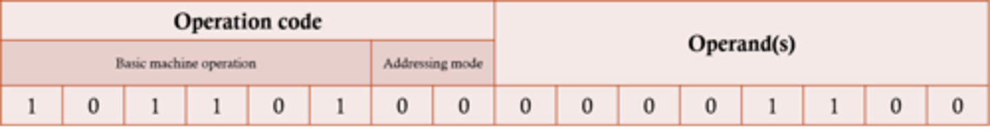
Opcode
Operation code which includes...
the actual command the processor needs to carry out, eg. ADD, SUB, etc.
the addressing mode - specifies whether the operand is the actual data, the memory address where the data is held, or a register
Operand
one or more items of data that are to be used in the instruction
This data may be either:
An actual value that can be used as presented
The address in memory where the data to be used is held
The register where the data is held
Instruction example
The number of bits allocated to the opcode and operand will vary according to the processor used
The example here shows a possible arrangement for an instruction used in a processor with a 16-bit word length

Addressing mode
Typically two bits
Specifies whether the data is:-
An actual value that can be used as presented
The address in memory where the data to be used is held
The register where the data is held
Immediate Addressing
The operand is the actual value to be used in the instruction
The addressing mode 00 specifies that the data is a value (12 in this case), not an address
e.g. ADD 5 ;Add 5 to contents of accumulator ;5 is operand.
Immediate Addressing benefit
No memory reference other than the instruction fetch is required to obtain the operand, thus saving one memory or cache cycle in the instruction cycle
Immediate Addressing drawback
The size of the number is restricted to the size of the address field, which, in most instruction sets, is small compared with the word length.
Direct addressing
The operand in this case is the address of the location in memory of the data to be used
The addressing mode 01 specifies that the data is an address, not a value
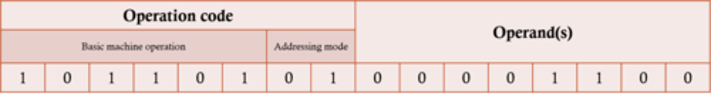
Direct addressing example
LDD 35
the MAR is loaded with the operand of the instruction // loaded with 35
• the Accumulator is loaded with the contents of the address held in MAR
// the Accumulator is loaded with the contents of the address 35
Direct addressing benefit
Can be fast - but not as fast as immediate addressing
Direct addressing drawback
Code depends on the correct data always being present at same location.
Generally a good idea to avoid referring to absolute memory addresses in order to have 're-locatable code' i.e. code that does not depend on specific locations in memory
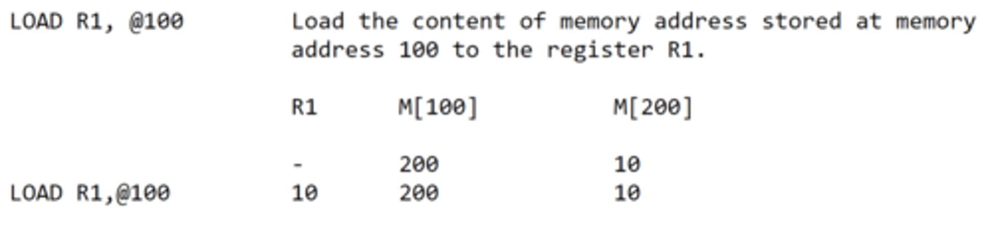
Indirect Addressing
The operand is the address of the address of the value to be used
Indexed Addressing
Modifies the address in the operand by the addition of a number held in a special-purpose registers, called an index register
Before the address is used. Index registers are quickly and easily altered providing an efficient way of accessing a range of memory locations, such as in an array.
Indexed addressing example
The operand plus contents of index register is the address of the value to be used
Assume the Index register holds the below
0 0 0 0 1 1 1 0
The instruction LDX 113 is executed
The processor would then calculate 113 + 13 = 126
Then the contents of memory location 126 will be stored in the accumulator
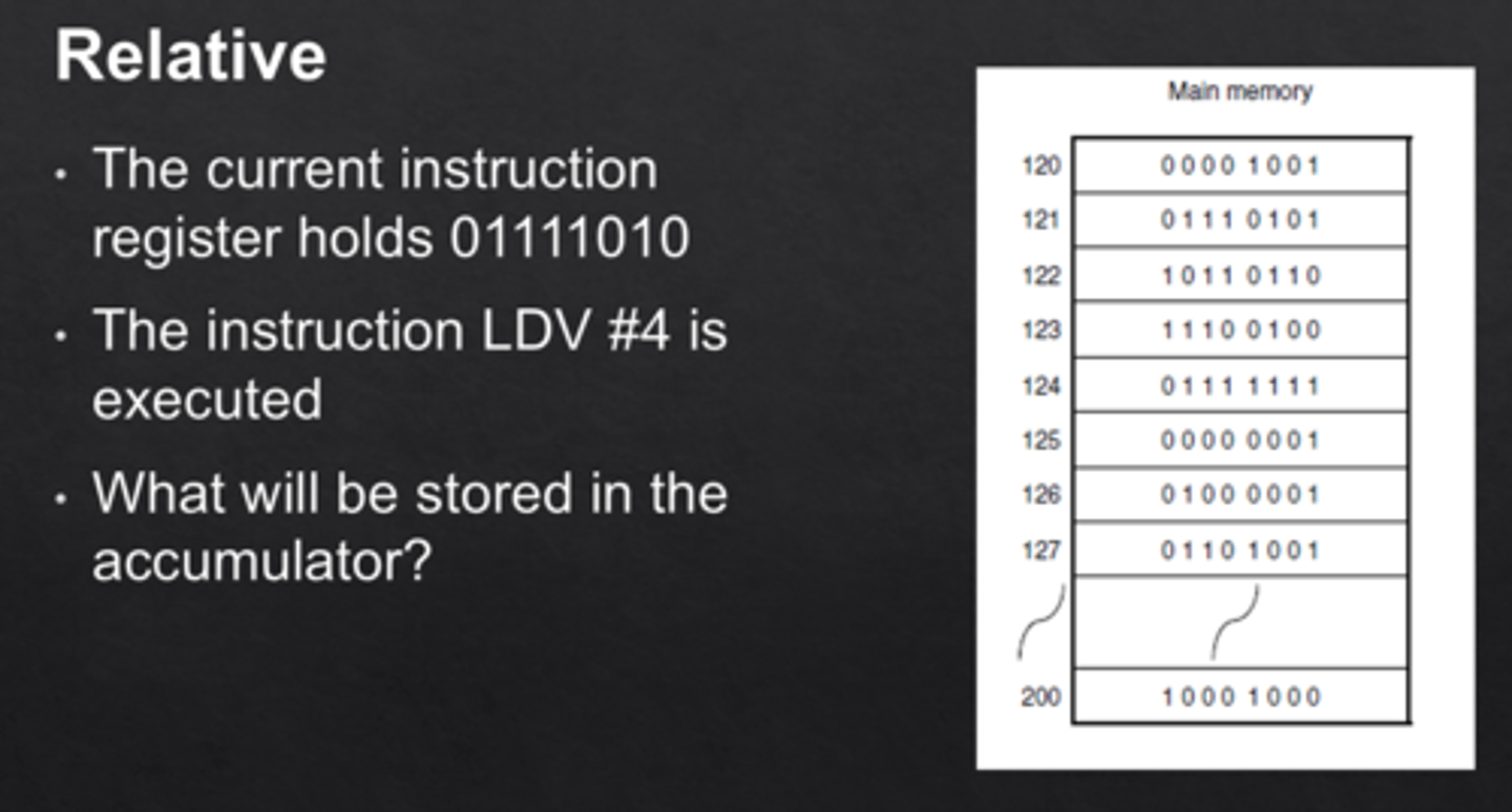
Relative Addressing
The next instruction to be carried out is an offset number of locations away, relative to the address of the current instruction.
A small offset is added to the current address in the program counter. (Remember that the program counter always points to the next instruction to be executed).
Assembly Language
Programming language that has the same structure and set of commands as machine languages but allows programmers to use symbolic representations of numeric machine code i.e. mnemonics.
Easier to learn then machine code but harder than a high level language e.g. Python
Both Assembly and machine code are low level languages
Assembly generally has a one-to-one relationship with machine code
High level advantages
Much easier and faster to write, debug and maintain programs
They provide higher level of abstraction from machine languages - easier to learn
Different high-level languages have been written specifically for different types of problem
Portable - a program written for one type of computer can be recompiled for a different type of computer
High level disadvantages
It takes additional translation times to translate the source to machine code
High-level programs are comparatively slower than low-level programs.
Compared to low-level programs, they are generally less memory efficient.
Most high-level languages do not have statements to allow the programmer to manipulate individual bits - essential in some applications, e.g. device drivers
Assemblers
Translate from assembly language to machine code.
Some assemblers scan the assembly language program twice; these are referred to as two-pass assemblers
Compiler
The software reads the source code and reports all errors. The software produces an executable file.
Translates a high-level language program into machine code for the processor to execute.
Interpreter
The software reads each statement and checks it before running it. The software halts when it encounters a
syntax error.
Translates a high-level language program into machine code for the processor to execute.
Macro
A group of instructions given a name // subroutine
A group of instructions that need to be executed several times within the same program
The statements are written once and called using the name whenever they need to be executed
Macro code is inserted into the source file at each place it is called
Compiler and interpreter differences
Compiler creates an executable//an interpreter does not create an executable.
• The compiled program can be independently distributed.
• Compiler reports all errors at the end of compilation//an interpreter stops when it reaches an
error.
• Interpreter executes each statement immediately after decoding/checking it//a compiler checks the whole program for errors.
• The interpreter software/source code must be present in main memory every time the program is executed//the compiled program does not require compiler/source code to be present.
• Cross-compilation is possible/compile on one hardware platform to run on another.
Directive
An instruction that directs the assembler to do something
A directive is not a program instruction
It is information for the assembler
examples
State the start address for the program
tell the assembler to set aside pace for variables include an external file etc.
Absolute address
An address that references an actual, real address in memory
Symbolic addressing
Mode of addressing used in assembly language programming where the programmer uses labels for specific addresses in the program.
ORG
The origin (ORG) instruction tells the assembler the address of the memory location for the next instruction
ORG is entered at the beginning of a program.
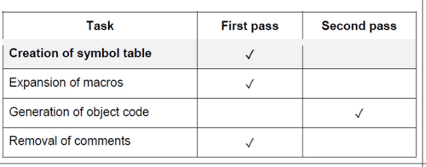
Two pass assemblers - First pass
Any directives are acted upon
Creation of symbol table
Any symbolic address is added to the symbolic address table
Data items are converted into their binary equivalent
Removal of comments

Two pass assemblers - second pass
Any symbolic address is replaced by an absolute address
Forward references are resolved
Generation of object code
How assemblers make entries to symbol table
1. The assembler scans the assembly language instructions in sequence
2. When it meets a symbolic address it checks to see if already in symbol table
3. If not, it adds it to the symbol table in the symbolic address column
4. If it is already in symbol table check if absolute address known
5. If the absolute address is known, it is entered in the appropriate cell
6. If the absolute address is not known mark / leave as unknown
USB connection
A voltage change occurs when the drive is plugged in
The computer detects this voltage change
The code of the device is transferred to computer...
... the OS finds the code of the device in the list of devices...
... and loads the appropriate device driver
USB (universal serial bus) benefits
devices automatically detected and configured when first attached/plug and play
• it is nearly impossible to wrongly connect a device
• USB has become an industrial standard
• supported by many operating systems
• USB 3.0 allows full duplex data transfer
• later versions are backwards compatible with earlier USB systems
• allows power to be drawn to charge portable devices
VGA
Video Graphics Array
Analog Video Output
Common on older PCs
Lacks audio support and advanced features compared to modern interfaces.
Adapters are often used to connect VGA devices to newer display interfaces.
HDMI
High Definition Multimedia Interface
Transmits audio and video through a single digital cable, simplifying connections.
Supports high-quality HD and UHD video with high bandwidth.
Plug-and-Play - Allows connecting/disconnecting devices without system restart.
Universal Connectivity: Found on TVs, computers, gaming consoles, and more, providing a common interface.
HDMI benefits over VGA
Faster transfer rates...
...needed for high resolution
Supports the high resolution of the monitor
Supports video and audio transfer between computer and monitor speakers...
... so no separate sound cable is needed
Digital interface therefore no data is lost in transfer to analogue and back
Less prone to error/crosstalk/external interference
Logical Shift
Moving bits either left or right, where bits that are lost are replaced by 0 on the other side. E.g. 10101111 shifted left logically 3 times, becomes 01111000.
- A lost 1 on the left side is an overflow error
- A lost 1 on the right side is also loss in precision
- Underflow is also possible (number smaller than smallest representation possible)
Arithmetic Shift
A similar shift, where the sign of the value is preserved in the MSB when shifting right. e.g. 10101111 shifted right arithmetically 3 times, becomes 11110101.
- Used of multiplying/dividing in powers of two - e.g. a single shift right is dividing by 2.
Cyclic Shift
No bits are lost – bits shifted out of one end are replaced on the other end.
10101111 shifted left cyclically 3 times would be 01111101
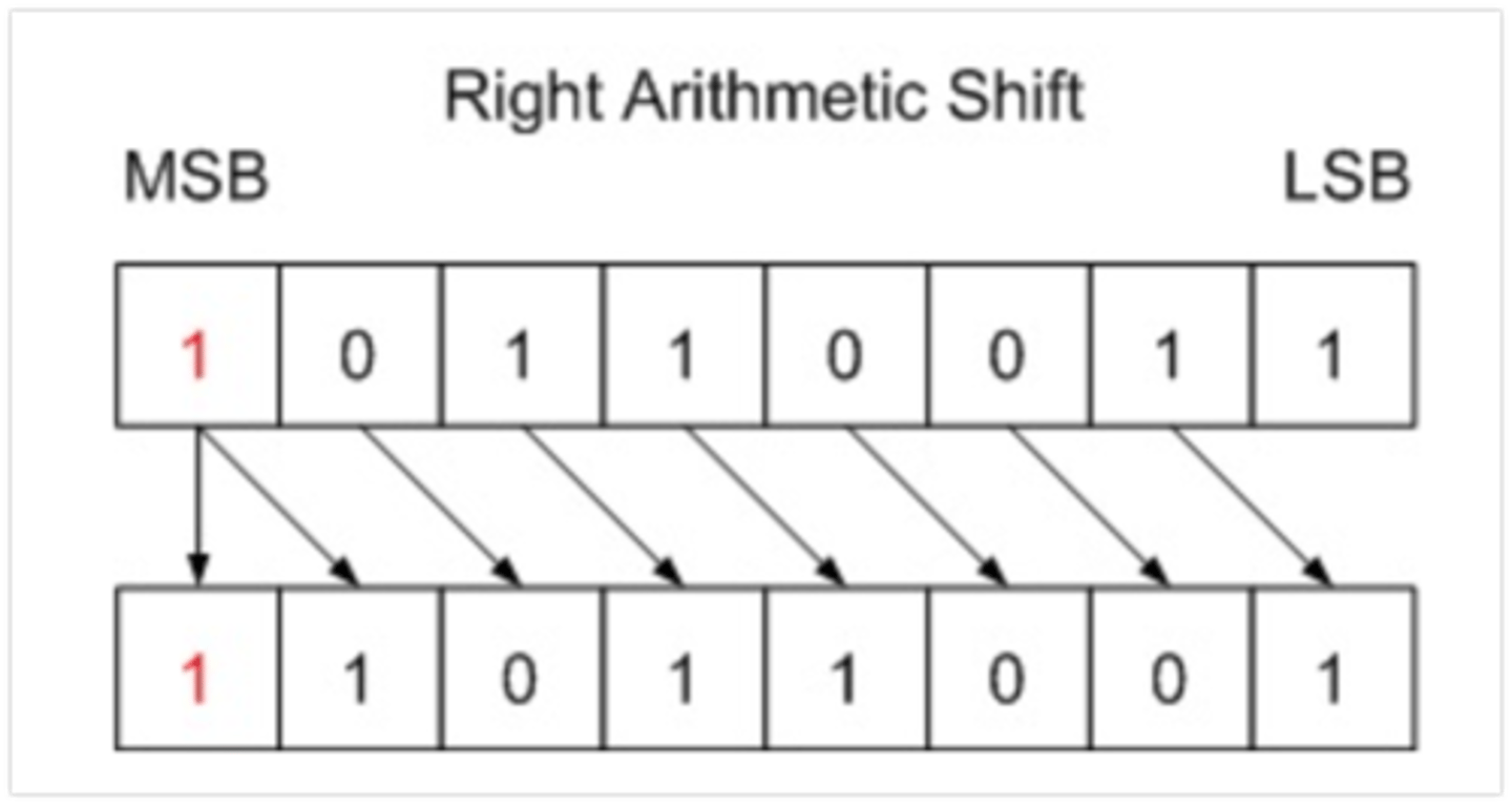
Right Arithmetic Shift
A Right Arithmetic Shift of one position moves each bit to the right by one. The least significant bit is discarded and the vacant MSB is filled with the value of the previous (now shifted one position to the right) MSB.
i.e. if negative, it is filled with 1s, if positive filled with 0s.
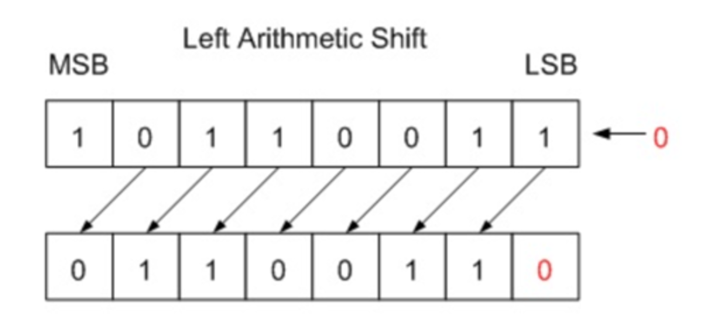
Left Arithmetic Shift
•A Left Arithmetic Shift of one position moves each bit to the left by one. The vacant least significant bit (LSB) is filled with zero (even if negative number) and the most significant bit (MSB) is discarded. It is identical to Left Logical Shift!
•Shifting left on signed values can work, but overflow occurs when the most significant bit changes values (from 0 to 1, or 1 to 0).