CHAPTER 4. PROCESSOR FUNDAMENTALS
1/36
There's no tags or description
Looks like no tags are added yet.
Name | Mastery | Learn | Test | Matching | Spaced |
|---|
No study sessions yet.
37 Terms
Show understanding of the basic Von Neumann
model for a computer system and the stored
program concept
Key components:
Central Processing Unit (CPU): This is the brain of the computer, it carries out instructions and performs calculations.
Memory: This stores both data (information) and instructions (programs).
Input/Output (I/O): This allows the computer to communicate with the outside world, like receiving input from a keyboard and displaying output on a monitor.
Control Unit: This part of the CPU fetches instructions from memory, decodes them, and directs other parts of the computer to carry them out.
Arithmetic Logic Unit (ALU): This performs arithmetic operations (addition, subtraction) and logical operations (decisions based on true/false).
Connections:
These components are connected by a system bus that allows them to transfer data and instructions.
Special purpose registers and their uses.
PC
MDR
MAR
ACC
PC.-stores the address where the next instruction to be read can be found.
MDR- acts like a buffer and holds anything that is copied from the memory, ready for the processor to use.
MAR-stores the address of the memory location currently being read from or written to.
ACC-(temporary register)used by the ALU to store a value for the execution of an instruction.
IX(not used in f-e cycle.)
CIR
Status register (not used in f-e cycle.)
IX-used for modifying operand address during the running of a program typically for vector
CIR-holds the instruction that is to be executed.
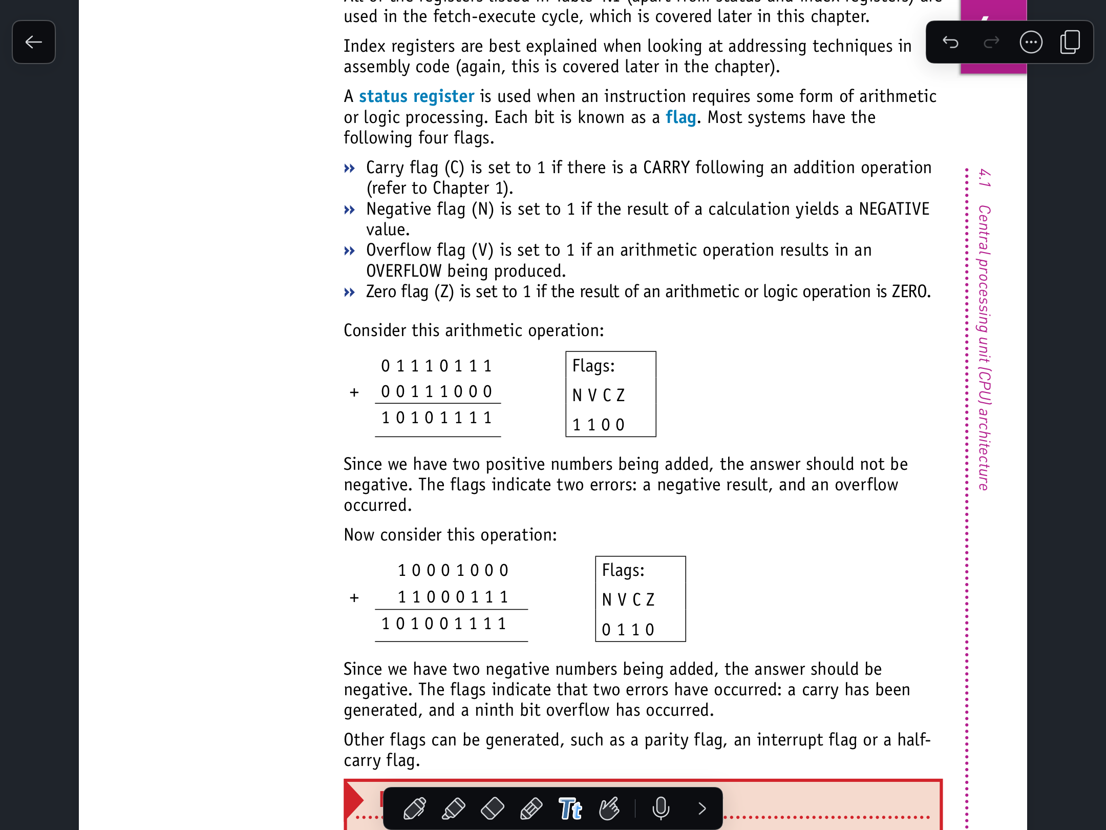
SR.- contains bits which can be set or cleared depending on the operation (for example, to indicate overflow in a calculation)
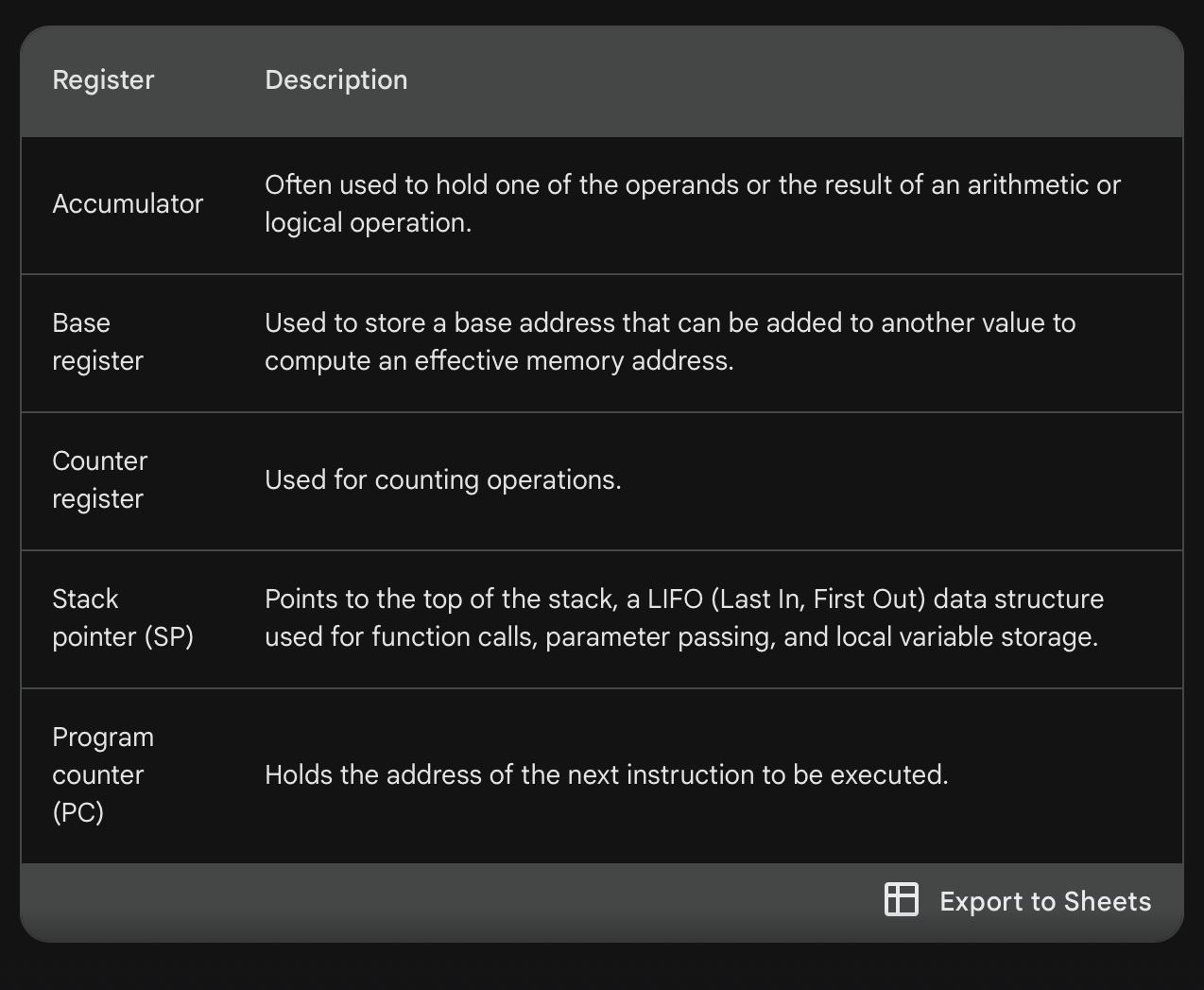
General purpose registers
The number and specific functions of GPRs can vary depending on the CPU architecture. However, they typically include:
Data registers: These registers are used to store operands for arithmetic and logical operations.
Address registers: These registers are used to store memory addresses.
Flag registers: These registers store status flags that indicate the outcome of previous operations.
Special-purpose registers: These registers have specific functions, such as holding the program counter (PC),which keeps track of the instruction currently being executed.
Find out what conditions could cause:
a) a parity flag (P) being set to 1
b) an interrupt flag (I) being set to 1
c) a zero flag (Z) being set to 1
d) a half-carry flag (H) being set to 1.
e) a carry flag(C) is set to 1.
f) a negative flag (N)is set to 1
g) an overflow flag (V)is set to 1.
h) a zero flag(Z) is set to 1.
System buses.
Data lines: These carry the actual information being transferred, like instructions or data being processed.
Address lines: These tell the receiving device where the data is coming from or where it should be sent.
Control lines: These lines control the flow of data on the bus, like signaling when data is being sent or received
Here are some of the benefits of using system buses:
Reduced complexity: Less wiring is needed because components don't need individual connections to each other.
Scalability: New components can be added to the system more easily by connecting them to the bus.
Modular design: Buses allow for a more modular design where different parts of the computer can be designed and manufactured independently.
Show understanding of the purpose and roles of the system clock, Immediate Access Store (IAS)
System Clock:
Imagine a conductor in an orchestra keeping everyone in time. The system clock is similar. It's a small electronic circuit that generates a steady stream of pulses at a very precise frequency.
This constant flow of pulses acts as a reference point for all the other components in the computer.
The CPU (central processing unit) relies on the clock signal to synchronize its operations. Each pulse might tell the CPU to fetch the next instruction, perform an operation, or move data around.
Immediate Access Store (IAS):
Think of your desk, where you keep the things you're actively working on. The IAS, also sometimes called cache, is a small but very fast type of memory located within the CPU.
It stores a limited amount of data and instructions that the CPU is currently using or is likely to need next. This is similar to how you might keep a notebook and pen on your desk for quick access while working on a project.
The advantage of IAS is its speed. Since it's right next to the CPU, data can be retrieved much faster than from the main memory, which is like filing away completed tasks in a cabinet. This significantly improves the overall performance of the computer.
Working Together:
The system clock ensures all the components are in step, and the IAS provides quick access to essential data, both working together to keep the computer running smoothly and efficiently.
Show understanding of how factors contribute to the performance of the computer system
processor type and number of cores-the more cores the faster the processor carries out its task(dual, single, quad core etc.
• the bus width
• clock speed-defines the shortest possible time that any action can take. Increase clock speed, decrease execution time, more cycles per unit time, increase performance. Limit on clock speed.
• cache memory (fastest component of IAS) performance of cpu increases if cache memory increases with size.
Understand how diferent ports provide connection to peripheral devices
USB (Universal Serial Bus): This is the most widely used port today. It can connect a wide range of devices, including external hard drives, flash drives, printers, keyboards, mice, and cameras. USB ports can also provide power to some devices.
HDMI (High-Definition Multimedia Interface): This port is used to connect high-definition displays like TVs and monitors to computers. It can also transmit audio signals
Video Graphics Array (VGA): This is a type of connector and standard for analog video output for computers. It was widely used in the past to connect computers to monitors but has largely been replaced by digital interfaces like DVI and HDMI.
Show understanding of the purpose of interrupts
Handling input/output (I/O) operations: When a device like a keyboard or network card needs the CPU's attention, it can send an interrupt to signal that it has data to send or receive. This allows the CPU to efficiently manage I/O operations without constantly checking if devices need attention.
Responding to timers: Timers can generate interrupts at regular intervals to signal the need for specific tasks, like updating the system clock or running background processes.
Handling errors: Hardware malfunctions or software bugs can trigger interrupts to alert the CPU of a potential problem. This allows the system to take corrective action and prevent crashes.
possible causes of interrupts
Device-related: These interrupts are triggered by hardware devices that need the CPU's attention. This could be because:
A device needs data from the CPU (e.g., a hard drive ready to transfer data).
A device has data for the CPU (e.g., a keyboard key being pressed).
A device has encountered an error (e.g., a printer running out of paper).
Time-based: These interrupts are generated by timers within the computer system at regular intervals. This allows the CPU to keep track of time and perform tasks that need to happen at specific moments.
Program-related: In some cases, software can generate interrupts. This might be done to:
Signal the completion of a lengthy operation.
Request a specific service from the operating system.
Report an error within the program.
applications of interrupts
Real-time tasks:
Interrupt requests from timers ensure the CPU handles critical tasks that need to happen at precise moments.
This is essential for real-time systems like controlling industrial machinery or processing audio/video data.
Input/Output (I/O) operations:
Interrupt requests from devices like keyboards or network cards signal the CPU when they have data to transfer.
This allows the CPU to efficiently manage I/O operations without constantly checking if devices need attention.
Error handling:
Hardware malfunctions or software bugs can trigger interrupts to alert the CPU of a potential problem.
This allows the system to take corrective action and prevent crashes.
Multitasking and responsiveness:
By prioritizing interrupts, the CPU can respond to user input or critical events even while working on other tasks.
This helps keep the system feeling responsive and allows users to interact with it smoothly.
use of an Interrupt Service handling Routine
(ISR) when interrupts are detected during the fetch-
execute cycle
Here's how ISRs work in relation to the fetch-execute cycle:
Fetch-execute cycle: The CPU is constantly working in a fetch-execute cycle. It fetches an instruction from memory, decodes it, and then executes it.
Interrupt happens: During any stage of the fetch-execute cycle, an interrupt can occur. This could be a signal from a device like a keyboard or a timer interrupt.
CPU acknowledges interrupt: The CPU recognizes the interrupt and temporarily halts its current instruction.
Save state: The CPU stores the state of the current process, including the program counter (which keeps track of the instruction being executed). This allows the CPU to return to the same place after handling the interrupt.
Determine ISR: The CPU uses an interrupt vector table (IVT) to identify the appropriate ISR for the specific interrupt source. The IVT is like a list that maps interrupt sources to ISR locations in memory.
Execute ISR: The CPU loads and executes the ISR code.
ISR handles interrupt: The ISR performs the necessary actions to service the interrupt, such as reading data from a device or acknowledging a timer event.
ISR finishes: Once the ISR finishes its task, it signals the CPU.
Restore state: The CPU restores the saved state of the interrupted process, including the program counter.
Resume fetch-execute cycle: The CPU resumes the fetch-execute cycle from where it left off before the interrupt
how interrupts are handled
Interrupt occurs: A hardware device (like a keyboard) or software program sends a signal to the CPU requesting its attention. This is like a notification that something important needs to be handled.
CPU acknowledges interrupt: The CPU recognizes the interrupt and temporarily pauses its current work. Imagine the CPU is busy working on a task, but it acknowledges the interrupt and puts the task on hold for a moment.
Save state (optional): In some cases, the CPU might store the state of the current task before moving on. This is like the CPU bookmarking its place in its work so it can easily return to it later.
Determine ISR: The CPU uses an interrupt vector table (IVT) to identify the appropriate ISR (interrupt service routine) for the specific interrupt source. The IVT is like a list that maps interrupt sources to specific locations in memory where the ISR code is stored.
Execute ISR: The CPU loads and executes the ISR code. The ISR is a small program designed to handle the specific interrupt that occurred.
ISR handles interrupt: The ISR performs the necessary actions to service the interrupt. This might involve:
Reading data from a device (like a key press from the keyboard)
Sending data to a device (like displaying something on the monitor)
Acknowledging an event (like a timer interrupt)
ISR finishes: Once the ISR completes its task, it signals the CPU.
Restore state (if needed): If the CPU saved the state before, it now restores it to resume the interrupted task.
Resume normal operation: The CPU resumes its previously paused task or continues to the next instruction if there was no saved state.
Show understanding of the relationship between assembly language and machine code
Machine code: This is the most basic set of instructions a computer can understand. It's a series of 0s and 1s that directly correspond to the internal operations of the CPU (central processing unit). Think of it as the raw, electrical instructions that the CPU can directly execute.
Assembly language: This is a human-readable version of machine code. It uses short codes, called mnemonics, and abbreviations that are easier for programmers to understand than binary code. For example, instead of a long string of 0s and 1s, assembly language might use "ADD" to represent the addition operation.
Here's an analogy: Imagine you have a remote control for a TV.
The machine code would be like the specific electronic signals the remote sends when you press a button. The TV's internal circuits understand these signals and perform the corresponding action (like changing channels).
Assembly language would be like labeling the buttons on the remote with words like "Volume Up" or "Channel Down." It's easier for humans to understand what each button does, but behind the scenes, the remote is still sending the same electronic signals.
Describe the diferent stages of the assembly process for a two-pass assembler
A two-pass assembler translates assembly language instructions into machine code in two distinct stages:
Pass 1: Symbol Table Generation and Parsing
In the first pass, the assembler reads the assembly language program line by line.
It focuses on identifying and understanding the overall structure of the program. Here's what happens:
Symbol identification: The assembler scans for labels (symbolic names assigned to memory locations) and stores them in a symbol table. This table acts like a dictionary, keeping track of where each symbol is used in the program.
Syntax analysis: The assembler checks if the instructions follow the correct assembly language format. It verifies things like proper instruction mnemonics (short codes for operations) and operand usage.
Error checking: The assembler identifies any errors in the code, such as undefined symbols or syntax violations. It reports these errors to the programmer so they can be corrected before moving on.
Parsing: The assembler breaks down each instruction into its component parts, like the operation code (opcode) and operands. This helps prepare the instructions for the next stage.
Pass 2: Machine Code Generation
In the second pass, the assembler uses the information gathered in pass 1 to generate the actual machine code for the program. Here's how it works:
Instruction translation: The assembler uses the symbol table to replace symbolic references (labels) with their actual memory addresses. This is like filling in the blanks in the instructions with the correct memory locations.
Opcode generation: The assembler translates assembly language mnemonics (like "ADD" or "STORE") into their corresponding machine code opcodes (numerical codes understood by the CPU).
Machine code generation: The assembler combines the opcodes and resolved addresses to generate the final machine code instructions. This is the binary code that the computer can directly execute.
Word
A small number of bytes that can be handled as a unit by the computer system.
Show understanding that a set of instructions are grouped
• Data movement
• Input and output of data
• Arithmetic operations
• Unconditional and conditional instructions
• Compare instructions
Input/output (I/O) instructions: These instructions allow the processor to interact with devices like keyboards,monitors, or storage drives. This is how the processor receives data from external sources or sends data to be displayed or stored.
Arithmetic operations instructions: These instructions perform mathematical operations on data, such as addition,subtraction, multiplication, and division. This allows the computer to perform calculations.
Unconditional jump instructions: These instructions tell the processor to jump to a specific location in the program code, regardless of any conditions. This is like changing the flow of the program without any checks.
Conditional jump instructions: These instructions tell the processor to jump to a specific location in the program code only if a certain condition is met. This allows for decision-making within the program based on calculations or input received.
Comparison instructions: These instructions compare two pieces of data and set a flag in the processor to indicate the result (e.g., equal to, greater than, less than). This allows the program to make decisions based on the comparison results.
Show understanding of and be able to use diferent modes of addressing
Including immediate, direct, indirect, indexed, relative
Immediate Addressing:
The operand value is directly included in the instruction itself. This is convenient for constants or small values that don't require separate memory allocation.
Example:
MOV EAX, 10(Move the immediate value 10 into register EAX)
Direct Addressing:
The operand's memory address is explicitly stated in the instruction. This is useful when you know the exact location of the data in memory.
Example:
MOV AX, [1000h](Move the value from memory location 1000h into register AX)
Indirect Addressing:
The address of the operand is stored in another memory location, and the instruction uses that address to reach the actual data. This can be useful for dynamic memory allocation or working with data structures like linked lists.
Example:
MOV EAX, [BX](Move the value from the memory location whose address is stored in register BX into EAX)
Indexed Addressing:
A base address and an index value are used to calculate the effective address of the operand. This is useful for accessing elements within arrays or tables. The base address is typically a fixed memory location, and the index value can be a register or a constant that varies to access different elements.
Example:
MOV AL, [ESI + 4](Move the value from the memory location 4 bytes away from the address stored in ESI into register AL)
Relative Addressing:
The operand's address is calculated relative to the current instruction's address. This is often used for jumps and branches within a program, as the distance to the target instruction can be specified instead of its absolute address.
Example:
JMP SHORT +8(Jump to the instruction 8 bytes forward from the current instruction)
Show understanding of and perform binary shifts
Logical, arithmetic and cyclic left, right.
Show understanding of how bit manipulation can be used to monitor/control a device
Carry out bit manipulation operations Test and set a bit (using bit masking)
Immediate Addressing:
The operand value is directly included in the instruction itself. This is convenient for constants or small values that don't require separate memory allocation.
Example:
MOV EAX, 10(Move the immediate value 10 into register EAX)
Direct Addressing:
The operand's memory address is explicitly stated in the instruction. This is useful when you know the exact location of the data in memory.
Example:
MOV AX, [1000h](Move the value from memory location 1000h into register AX)
Indirect Addressing:
The address of the operand is stored in another memory location, and the instruction uses that address to reach the actual data. This can be useful for dynamic memory allocation or working with data structures like linked lists.
Example:
MOV EAX, [BX](Move the value from the memory location whose address is stored in register BX into EAX)
Indexed Addressing:
A base address and an index value are used to calculate the effective address of the operand. This is useful for accessing elements within arrays or tables. The base address is typically a fixed memory location, and the index value can be a register or a constant that varies to access different elements.
Example:
MOV AL, [ESI + 4](Move the value from the memory location 4 bytes away from the address stored in ESI into register AL)
Relative Addressing:
The operand's address is calculated relative to the current instruction's address. This is often used for jumps and branches within a program, as the distance to the target instruction can be specified instead of its absolute address.
Example:
JMP SHORT +8(Jump to the instruction 8 bytes forward from the current instruction)
Port
The word "port" has a few different meanings:
In a computer network, a port is a virtual endpoint that identifies a specific service or process. Different ports are used for different types of traffic, like web browsing (port 80) or email (port 25). This way, a computer can tell which program incoming data is intended for.
A physical port is a connection point on a device where you can plug in a cable or other peripheral device. There are many different types of physical ports, including USB ports, HDMI ports, and headphone jacks.
Difference between synchronous and asynchronous serial data transmission
Synchronization:
Synchronous: Relies on a shared clock signal between the sender and receiver to keep them in sync. This ensures both devices are reading data at the right time. Think of it like two dancers following the same rhythm.
Asynchronous: Doesn't use a shared clock. Instead, start and stop bits are added to each data character (byte) to signal the beginning and end. This allows for more flexibility in transmission speeds, but can be less efficient.Imagine Morse code, where dots and dashes represent characters, and the spaces between them signal the end of a character.
Applications:
Synchronous: Often used for high-speed data transfers like external hard drives or network connections.
Asynchronous: Commonly used for low-speed data transmission like keyboard and mouse communication, or communication between simple devices.
Stored program concept
This is a critical idea in the Von Neumann model. It means that both programs (instructions) and data are stored in the same memory unit.
This is different from earlier computers where programs were wired in or loaded from separate devices.
With stored programs, the computer can easily switch between different programs by loading them into memory as needed. This makes computers much more flexible and versatile.
Benefits and limitations of the Von Neumann model
Benefits:
The Von Neumann model with stored programs is a simple and effective design that has enabled the great progress of computers.
It allows for easy program changes and updates, making computers more adaptable for different tasks.
Limitations:
The Von Neumann model has limitations, such as the von Neumann bottleneck, which can limit processing speed due to the shared system bus. However, modern computer architectures address this bottleneck with techniques like caching and pipelining.
Show understanding of the relationship between assembly language and machine code
Machine code is the raw language the processor understands.
Assembly language is a more readable version of machine code for humans.
An assembler program translates assembly language instructions into machine code that the processor can execute
Describe the diferent stages of the assembly process to a given process for a two-pass assembler
A two-pass assembler translates assembly language instructions into machine code in two distinct stages:
Trace a given simple assembly language program
Show understanding that a set of instructions are grouped
Including the following groups:
Data movement
• Input and output of data
• Arithmetic operations
• Unconditional and conditional instructions
• Compare instructions
Show understanding of and be able to use diferent modes of addressing Including immediate, direct, indirect, indexed, relative