Question 1
1/34
There's no tags or description
Looks like no tags are added yet.
Name | Mastery | Learn | Test | Matching | Spaced | Call with Kai |
|---|
No analytics yet
Send a link to your students to track their progress
35 Terms
Fluid power systems
(i) Fluid power may be described as the transmission and control of energy by means of a pressurised fluid, either a liquid or gas. This term is used when discussing both Hydraulics and Pneumatics.
(ii) Farming, Waste Disposal, Construction, Aviation, Car manufacturing

Identify the symbols
1-Single acting cylinder
2-3/n Way Valve
3-5/n Way Valve
4-One-way f low control valve
5-Shuttle valve
6-Time delay valve, normally closed
7-Air service unit
8-Double acting cylinder
9-3/n Way Valve
Answer the following:
(i) A hydraulic system can be divided into the following sections:
1. The signal control section
2. The power section
(ii) Advantages: Any three from the following would secure full marks:
- Transmission of large forces using small components, i.e. great power intensity
- Precision positioning
- Even movements independent of load, since liquids are scarcely compressible and flow control valves can be used
- Smooth operation and reversal
- Good control and regulation
- Favourable heat dissipation
Disadvantages: Any one of the following would secure full marks.
- Pollution of the environment by waste oil (danger of fire or accidents)
- Sensitivity to dirt
- Danger resulting from excessive pressures (severed lines)
- Temperature dependence (change in viscosity)
- Unfavourable efficiency factor.
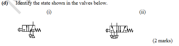
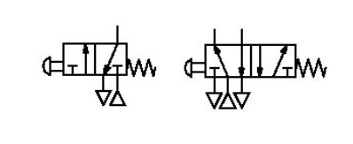
Identify the state of the valve
(i) Normal State (ii) Operated State
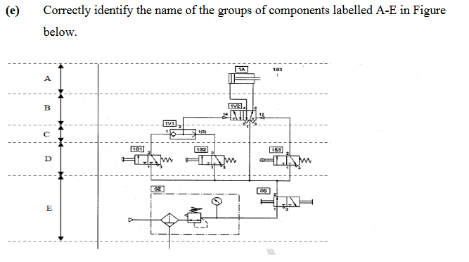
Correctly identify the name of the groups of components
A - Power components
B – Control elements
C – Processing elements
D – Input elements
E – Supply elements
Answer the following:
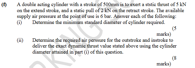
(i) The important power stroke for the cylinder is the outstroke.
A= Fextend/P =5000/( 6×10⁵ ) =8 . 33×10^−3 m^2
A= πD^2/4 =2 .78×10^−3 m^2
∴ D= √ (4 x 0 . 00833/3 .14) = 0 .103 m = 103 mm
The nearest standard diameter (from tables supplied) is 125mm diameter.
(ii) Required pressure for in-stroke =
From the supplied table, a standard cylinder with a piston diameter of 125mm has cylinder rod diameter of 32mm.
Fretract/A = 2000/[ π ( D2−d2 )/4 ] =2000/[ π ( 0 .1252−0 . 0322 )/4 ] =1.75 bar
Required pressure for out-stroke =
Fretract/A =5000/[ πD2/4 ] =5000/[ π ×0 . 1252/4 ] =4 . 1 bar
![<p><span style="color: rgb(255, 255, 255);"><span>(i) The important power stroke for the cylinder is the outstroke.</span></span></p><p><span style="color: rgb(255, 255, 255);"><span>A= Fextend/P =5000/( 6×10⁵ ) =8 . 33×10^−3 m^2<br>A= πD^2/4 =2 .78×10^−3 m^2<br>∴ D= √ (4 x 0 . 00833/3 .14) = 0 .103 m = 103 mm<br>The nearest standard diameter (from tables supplied) is 125mm diameter.</span></span></p><p><span style="color: rgb(255, 255, 255);"><span>(ii) Required pressure for in-stroke =</span></span></p><p><span style="color: rgb(255, 255, 255);"><span>From the supplied table, a standard cylinder with a piston diameter of 125mm has cylinder rod diameter of 32mm.<br>Fretract/A = 2000/[ π ( D2−d2 )/4 ] =2000/[ π ( 0 .1252−0 . 0322 )/4 ] =1.75 bar<br>Required pressure for out-stroke =<br>Fretract/A =5000/[ πD2/4 ] =5000/[ π ×0 . 1252/4 ] =4 . 1 bar</span></span></p>](https://knowt-user-attachments.s3.amazonaws.com/7f4c9c79-8565-40ab-8583-6a45c6d9c875.png)
State two types of valves commonly referred to as junction elements
Junction elements valves similar to shuttle/or valve, dual pressure valve/AND valve
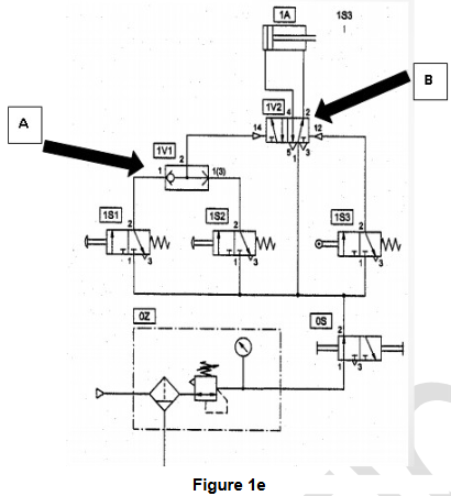
Correctly identify the function of the components labelled A (1V1) and B (1V2) in the schematic, Figure 1e attached.
A is a Shuttle/OR Valve
B is a 5/2 double pilot directional Control Valve
What is the correct term for a valve which controls an actuator?
Directional Control Valve
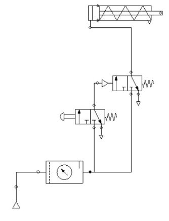
Identify the type of control and describe the operation in the schematic attached, figure 1k
Indirect control of a single acting actuator
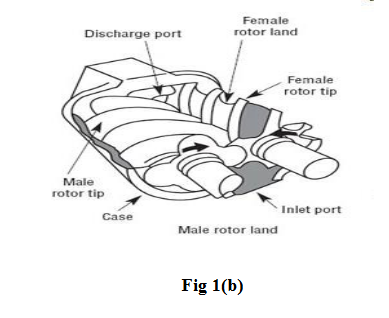
Answer each of the following in relation to Fig 1(b).
(i) Name the compressor shown and state its type.
(ii) Briefly describe the operation of this compressor.
(i) Screw compressor, a displacement compressor
(ii) Two meshing helical rotors continuously rotate in opposite directions. The design of the rotors is such that the free space between them decreases axially in volume and this decrease in volume compresses the air trapped between the rotors.
Answer each of the following:
(i) What are junction elements?
(ii) State the two types of valves commonly referred to as junction elements
(i) Any element that forms a junction between two air lines
(ii) Logic valves, AND, OR etc. and isolating or flow control valves
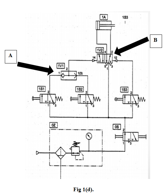
Correctly identify and describe the function of the components labelled A and B in Fig 1(d).
A is a shuttle/OR valve. This is a logic valve and allow operation from either signals (valves 1S1 or 1S2) to produce a signal on the outlet.
B is a 5/2 double pilot valve. This actuates the cylinder to either extend or retract with the respective momentary pulse signal from the valves (1V1 or 1S3)
Describe the following terms in relation to pneumatic/hydraulic cylinder control
(i) meter-in control
(ii) meter-out control
(i) Metre-in control refers to the control of a cylinder by varying/metering the flow to the cylinder via a flow control valve (flow to)
(ii) Metre-out control refers to the control of a cylinder by varying/metering the flow from the cylinder via a flow control valve (flow from)
Answer each of the following:
(i) State the type of movement possible using pneumatic actuation.
(ii) Briefly describe one practical example of pneumatic actuation. And state why it is preferred to other methods of actuation.
(i) Rotary and linear movement
(ii) Pick and place robot. Clean, fast, cheaper than other solutions, easily installed etc (similar answers)
Answer each of the following:
(i) Identify the state that is shown for the following valves in Fig1 (g).
(ii) State the code which covers graphical symbols for Fluid Power Systems and components.
(iii) List two components required to convert mechanical power to fluid power.
(i) 3/2 normally closed button spring return valve at rest and a 5/2 button spring return valve button pressed extending the actuator.
(ii) ISO 1219-1 (1991)
(iii) Cylinders, motors, compressors (any 2 )
Answer each of the following:
(i) Name the 2 sections into which a hydraulic system may be divided.
(i) A hydraulic system can be divided into the following sections:
1. The signal control section
2. The power section
Convert the following pressures to Pascals
i. 10 bar.
ii. 50m Water
iii. 15 psi
iv. 5 x 10^5 N/m2
i. 10 bar. =10 x10^5Pa
ii. 50m Water = 5 x 10^5Pa
iii. 15 psi = 1 x 10^5Pa
iv. 5 x 10⁵ N/m2 = 5x 10^5Pa
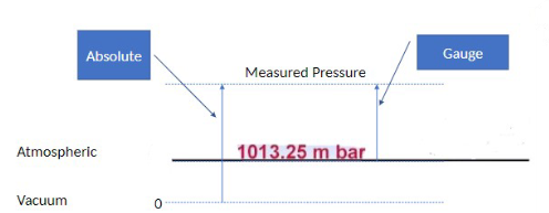
Explain the difference between Gauge Pressure and Absolute Pressure. Use a diagram to illustrate your answer.
Gauge pressure is the pressure in the pipeline and does not account for atmospheric pressure.
Absolute pressure = Gauge pressure and Atmospheric pressure
i. Define what Pressure is
ii. Show the equation P= F/A
iii. SI units associated.
i. Define what Pressure is
A force acting perpendicularly per unit area
ii. Show the equation P= F/A
iii. SI units associated. N/m2 or Pa
Calculate the pressure in bar to lift a 70kg load with diameter 50mm diameter pneumatic cylinder.
P= 70 x 9.81/( π 0.05^2/4 )=3.5 x 10^5 Pa(∨ N/m2 )
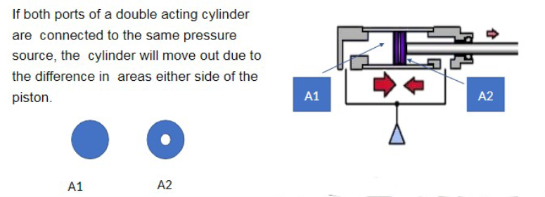
Explain why the force developed by a standard double acting cylinder, is larger on the outstroke than it is on the return stroke.
The greater the area the pressure can act on the greater the output force (F = PA)
A Positive Pump has a speed of 1250rpm. Determine the displacement volume if the volumetric flowrate, Q, is 3.5m^3/min, is to be achieved.
Q=V × Rpm
V = 3. 5/1250 =2.8 × 10^−3 m^3/rev
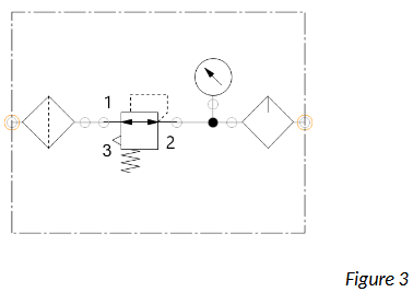
State the name of the following Pneumatic Symbol, Figure 3 and where it would be used.
Filter Regulator Lubricator or FRL
It is used between the compressor and the point of use, i.e. at the beginning of a pneumatic circuit.
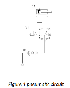
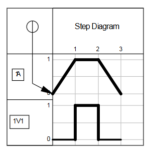
Draw the step diagram for the pneumatic circuit given below in figure 1
What Fluid property does Reynolds number indicate?
Fluid viscosity or the nature of flow of a liquid
State 5 contributors to the friction loss in a pipeline
Turbulent Flow
Laminar Flow
Pipe Roughness
Pipes Fittings
Diameter of pipe
Velocity of flow
Viscosity of the fluid (any 5)
Name 3 different flowmeters
Variable area Flowmeter or rotameter
Turbine Flow meter
Venturi Meter
Orifice Plate (any 3)
Name 3 ways that the flow of a liquid or gas can be quantified
Volumetric Flow (“Q” m3/min)
Mass Flow (“m” kg/min)
Velocity of Flow (“U” m/s)
Explain the term viscosity of a liquid, use examples of liquids to illustrate your answer
The properties of a liquid are largely determined by its resistance to flow, which is termed its viscosity. Fluid with a high viscosity such as syrup, deforms more slowly than fluid with a low viscosity such as water.
Name 5 compressed air plant components
Air Intake
Compressor
Aftercooler
Receiver or Vessel
Dryer or Moisture Separator
Pipework
Valves (any 5)
State 5 requirements of a receiver as used on a pneumatic compressor system.
Store Pressurised air or gas
Collect water vapour
Equalise Pressure
Reduce or dampen Pulse Flow
Aid the compressor control
Give examples of each of the following:
(i) Power Component
(ii) Supply element
(iii) Control element
(iv)Processing element
(v) Input element
Give examples of each of the following:
(i) Power Component ANS: Actuator, cylinder, rotary actuator
(ii) Supply element ANS: FRL, Service unit, compressor
(iii) Control element ANS: Directional Control Valve
(iv)Processing element ANS: Shuttle Valve dual pressure valve or similar
(v) Input element ANS: 3/2 push button spring return signal valve
Explain the principle of operation of a compressed air filter
Air filter: Air flow through this unit undergoes a sudden reversal of direction and a deflector cone swirls the air. Heavier water particles are flung out to the walls of the separator and to collect in the trap bottom from where they need to be drained at intervals.
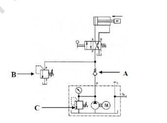
Correctly identify the name of the groups of components labelled A, B & C in Figure shown.
A = non return valve
B = Pressure relief Valve
C = Power pack pressure relief valve