Advanced Computer Graphics
1/25
There's no tags or description
Looks like no tags are added yet.
Name | Mastery | Learn | Test | Matching | Spaced | Call with Kai |
|---|
No analytics yet
Send a link to your students to track their progress
26 Terms
Difference between normal and bump mapping?
Bump mapping uses a grayscale texture that only perturbs the surface height.
Normal mapping uses an RGB texture where each pixel encodes a normal vector. Full control over normal orientation
LOD Management
Cost of rendering an Object O at a certain level L: Cost(O,L) The Benefit of rendering object O at L: Benefit(O, L)
Now for all objects in the view frustrum, we want to optimize the sum of the benefits under the constract that the sum of the cost is smaller than the target frametime. Approximation:
Cost(O,L): The average time to render object O at LOD L from different viewpoints
Benefit(O,L): The projected size of the bounding volume.
Selecting L for each O in S is a napsack problem. Instead we can use a greedy algorithm where we seek to maximize the value for each object:
Maximize value = (Benefit/Cost) for each object
Start with the objects of highest value (if equal, highest benefit is used)
Complexity is O(n log n)
Linear interpolation (LERP)
Fast
Angular velocity is not constant Lerp(t,q1,q2) = q1(1-t) + q2t
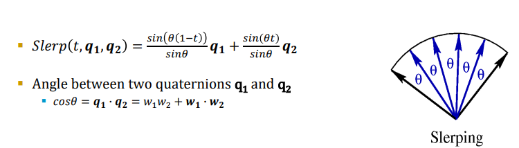
Spherical Interpolation (SLERP)
More computational demanding
Numerical instable when theta close to 0
Even rotation velocity (interpolates over the spherical arc) Slerp(t,q1,q2) = sin(θ(1-t))/sinθ)+ sin(θt)
Interpolation between multiple Quaternions?
SQUAD (Spherical Cubic Interpolation)
Uses iteration of three sleprps and is similar to the “de Casteljau algorithm”.
Squad(t; p, a, b, q) = Slerp(2t (1-t); Slerp (t; p, q), Slerp(t;a,b))
Describe how to derive the normal matrix.
Start with the upper-left 3×3 submatrix of the model-view matrix M (excluding translation components).
Compute the inverse of this 3×3 matrix: M3×3-1
Take the transpose of this inverse to get the Normal Matrix. N = (M3×3-1)T
What is the purpose of the Normal Matrix and why do we need it?
The normal matrix ensures correct transformations of normal vectors when the object undergoes non-uniform scaling, rotation and translations. Unlike position vectors, normal vectors need to be transformed using the inverse-transpose of the model-view matrix to preserve perpendicularity.
Without the Normal Matrix, lighting calculations would be incorrect, causing normals to be distorted and shading to look unrealistic.
Describe and illustrate how the shadow mapping method works.
Shadow mapping is a technique that determines if a fragment is in shadow by comparing its depth from the light’s perspective. The process involves two main steps:
Depth pass (Shadow Map Generation)
Render the scene from the light’s POV
Store the depth (distance to the light) of the closest surfaces in a shadow map (a depth texture).
Shading pass (Shadow Test)
Render the scene from the camera’s POV
Transform each fragment’s world position into the light coordinate space.
Compare its depth to the stored depth in the shadow map.
If the fragment is further than the stored depth, it is in shadow, otherwise it is lit
How can this method be extended for shadows on large areas
For large areas, a single shadow map may have low resolution, causing pixelated shadows (aliasing). Some techniques to improve shadow quality include:
Cascaded Shadow Maps (CSM) – Divide the scene into multiple regions (cascades) and use higher resolution shadow maps for near areas and lower resolution for far areas.
Directional Shadow Mapping (for sunlight) – Use an orthographic projection to cover large areas uniformly.
Tiled Shadow Maps – Split the terrain into smaller sections and generate shadow maps per section.
These methods balance performance and shadow quality over large distances.
Describe how soft shadows can be emulated
Soft shadows can be approximated by blurring or filtering the shadow edges. Some common techniques:
Percentage Closer Filtering (PCF) – Sample multiple nearby texels in the shadow map and average the results to create a soft transition.
Variance Shadow Mapping (VSM) – Stores depth and squared depth in the shadow map, allowing for smooth filtering using variance.
Poisson Sampling – Uses a random sampling pattern to reduce aliasing and create smoother shadows.
Screen-space Blur – Apply a Gaussian blur or similar filter to the shadow edges in post-processing.
Describe how Dynamic skybox can improve realism for moving objects.
A dynamic skybox updates in real-time to reflect changes in time of day, weather and lighting conditions. This improves realism for moving objects by ensuring that their shading, reflections and atmospheric effects remain consistent with the environment.
Key Improvements for Realism
Real-time Lighting Adjustments
As objects move, the light source (e.g., sun, moon) changes position.
A dynamic skybox updates ambient light and directional light accordingly, making moving objects appear more naturally lit.
Reflections on Moving Objects
Moving objects, especially metallic or glossy surfaces, reflect the skybox.
A static skybox would cause incorrect reflections, while a dynamic skybox updates reflections in real time.
Atmospheric Effects
Moving objects experience fog, clouds, and color shifts dynamically.
A dynamic skybox ensures that distant objects fade naturally and that motion through fog looks correct.
Parallax and Perspective Changes
A static skybox appears flat.
A dynamic skybox with parallax correction makes distant clouds, stars, and the sun appear correctly positioned as the player moves.
What is BRDF?
Bidirectional Reflectance Distribution Function
Describes how light is reflected from a surface at a certain wavelength.
Answers the following questions:
Assume light hit a point on a surface with the incoming direction of win and the outgoing direction wout, how much energy is reflected?
BRDF(win,wout)
This function describes the ratio between incoming light (Irradiance) at a certain point and leaving (radiance) at specified in and out directions
i.e. doesn’t work for subsurface scattering
The degree to which light is reflected depends on the viewer and light position relative to the surface normal and tangent
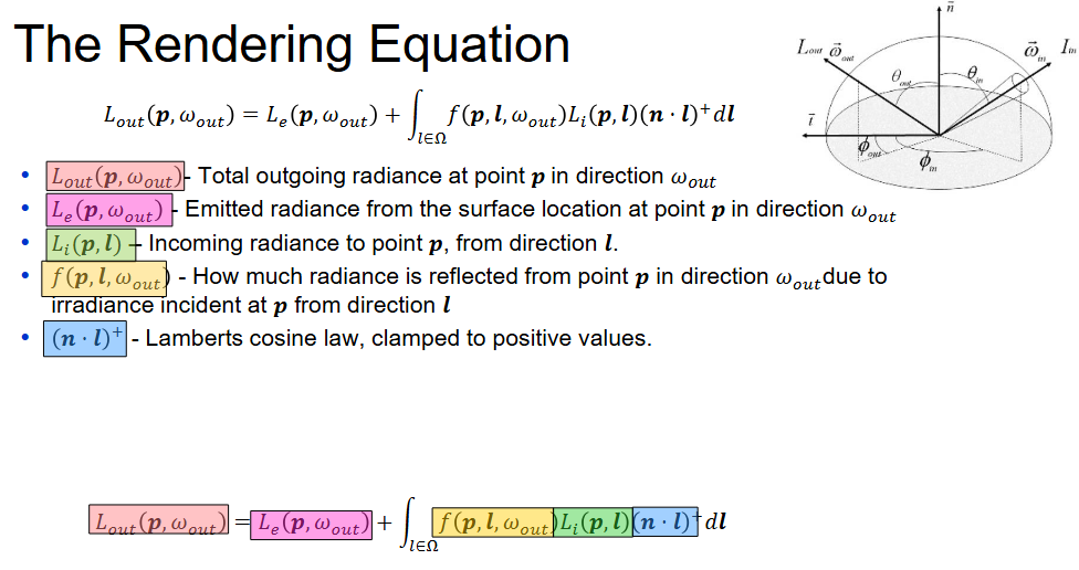
The rendering equation
What is position dependent vs. position independent BRDF?
Position-Dependent BRDF: This means the BRDF varies with the position on the surface. This can happen due to spatially varying material properties (e.g., textures, anisotropic surfaces) or local geometric effects (e.g., microfacet variations). However, all BRDFs still depend on view direction and light direction.
Position-Independent BRDF: This means the BRDF remains the same across the surface. The reflectance properties are uniform at every point, meaning there's no texture variation or spatial dependence.
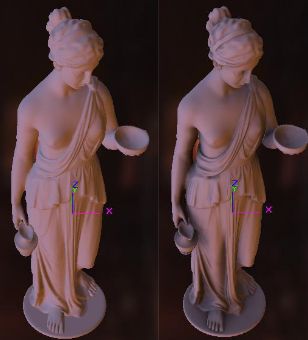
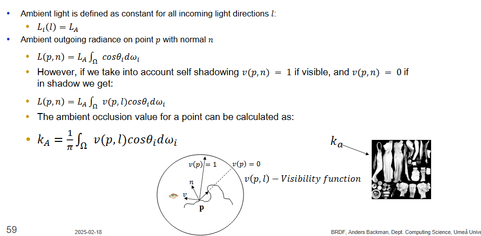
Describe what ambient occlusion is? What is the effect that we try to achieve with this rendering technique?
Shadow from ambient light is called Ambient Occlusion. They do not depend in light direction and hence can be precomputed (for static objects). We try to achieve self-shadowing on objects
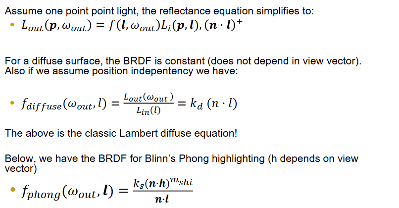
Write down the BRDF for Ambient Occlusion to illustrate how it comes into the rendering equation.
Write down the BRDF for Blinn phong and Labert diffuse
Difference between local and global illumination? What is the major goal of global illumination?
The goal of global illumination is to simulate the full interaction that objects have with each other in terms of lighting. A red object “leaks” red onto nearby objects for example.
The difference is that local illumination does not take other objects into account when calculating light (except for potentially shadows)
Describe techniques that can achieve a global illumination effect.
Path tracing
Raytracing only gives specular highlights. Path tracing also traces secondary reflections randomly. Uses a number of samples when calculating diffuse light (noise with few samples, needs a ton of samples to look good without noise). Not possible in real time until denoising was introduced. Meaning only 1 sample is needed that can then be “denoised”Photon mapping
A two pass method.
Pass 1:
Sends photons that are traced using ray tracing, interacts with objects in the scene. (absorbed, reflected or transmitted)
If diffuse, the photon is stored in the photon map
If specular, the photon is reflected
Collected photons are stored using a k-d tree for fast nearest-neighbor searches.
Pass 2:
Standard ray-tracing is used to compute the final image.
If the surface is diffuse, the radiance estimation is performed
Nearby photons are gathered, their contribution is estimated using a desntiy estimation technique.
If surface is reflective or refractive, recursive ray tracing is used to handle it.
Radiosity
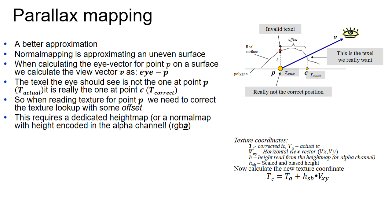
Describe and illustrate the algorithm for Parallax Mapping
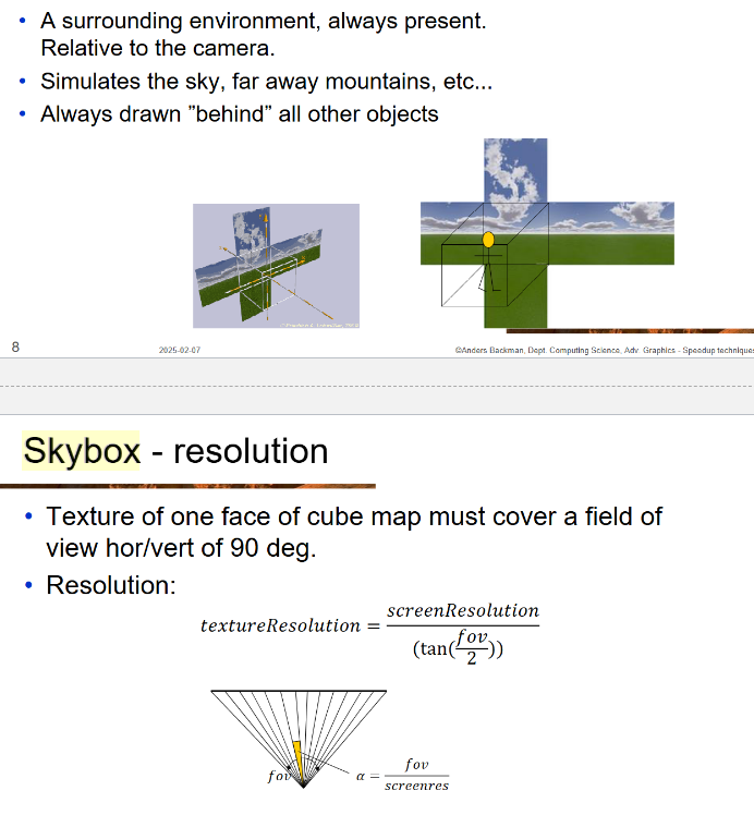
Describe and illustrate the generation and rendering of a skybox
To render a skybox:
Clear the depth and color buffers
Apply camera translation (not rotation)
Disable the depth buffer test and writes
Draw the skybox
Enable depth buffer test and writes
Draw the rest of the scene
Describe AAB, how to create it, what are its benefits and drawbacks?
Axis Aligned Bounding Box. Described by two points, minimum and maximum. Simply loop through vertices and find the minimum and maximum values for each axis.
+Simple to create
+Simple collision detection
-A lot of empty space enclosed
Describe Two algorithms for creating a Bounding Sphere, how to create it, what are its benefits and drawbacks?
Simple algorithm:
Create an AABB
Use centerpoint of AABB as center opf sphere
Use diagonal as radius (or better, loop through vertices and fine the one farthest from the center, this is the new radius)
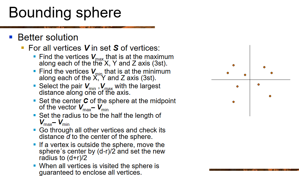
Better algorithm (picture)
+Simple to create
+Simple collision detection
-Could potentially be a bad choice for long thin objects.
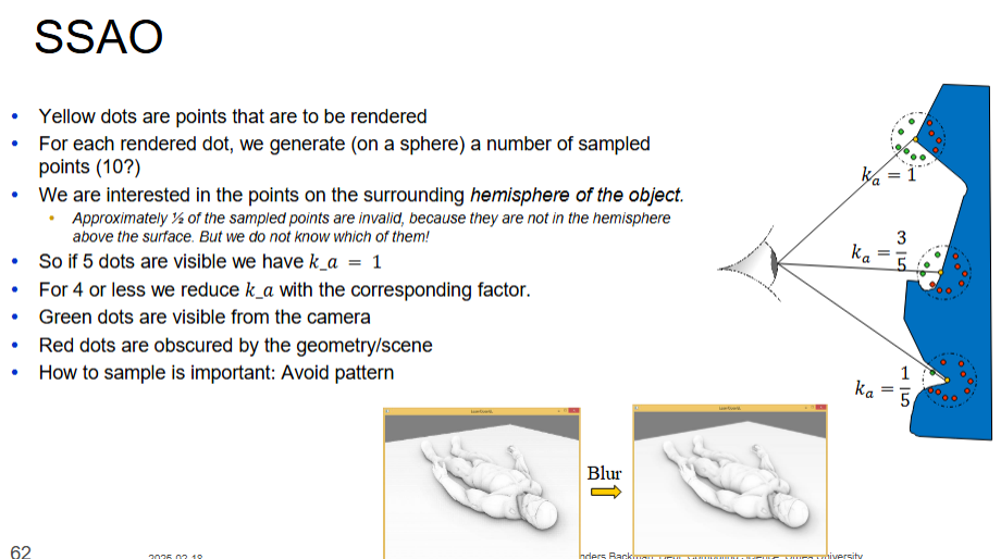
Describe the real time method for Ambient Occlusion (SSAO)
Three alternatives to represent a rotation. Strength and weakness?
There are three common ways to represent a rotation in computer graphics:
1. Euler Angles
Description: A rotation is represented using three angles (yaw, pitch, roll) applied sequentially around coordinate axes.
Strengths:
Intuitive and easy to understand.
Compact representation (only three values).
Efficient for simple rotations.
Weaknesses:
Gimbal lock: Loss of a degree of freedom when two axes align.
Order-dependent: Different rotation orders produce different results.
Difficult to interpolate smoothly.
2. Rotation Matrices
Description: A 3×3 matrix (or 4×4 in homogeneous coordinates) that transforms points or vectors in space.
Strengths:
No gimbal lock.
Easy to combine multiple transformations (multiplication of matrices).
Directly usable in transformation pipelines.
Weaknesses:
Requires 9 (or 16) values, making it memory-heavy.
Floating-point errors can cause matrix drift (not always perfectly orthonormal).
Not efficient for interpolation (e.g., SLERP is difficult).
3. Quaternions
Description: A four-component representation (w, x, y, z) that encodes rotation without using matrices.
Strengths:
No gimbal lock.
More compact than matrices (only 4 values).
Efficient for smooth interpolation (SLERP).
Weaknesses:
Less intuitive than Euler angles.
Requires specialized operations (e.g., quaternion multiplication).
Harder to debug due to abstract representation.
What does HRTF stand for, how does it work?
Head-Related Transfer Function. It models how sound interacts with the head, ears, and body before reaching the eardrums. It helps with 3D audio by using interaural time and level differences (ITD & ILD) and frequency filtering. Used in VR and spatial audio.
What is the difference between presence and immersion?
Immersion: The technical aspect of how well a system engages the senses (e.g., high-resolution visuals, spatial audio, and haptics).
Presence: The psychological feeling of "being there" in the virtual environment, influenced by immersion but also by interaction quality and realism.
Comparison:
Immersion is objective (hardware-driven), while presence is subjective (user perception).
High immersion can enhance presence, but presence also depends on user engagement and realism.