P4 - Electric Circuits
1/57
Earn XP
Description and Tags
Name | Mastery | Learn | Test | Matching | Spaced | Call with Kai |
|---|
No analytics yet
Send a link to your students to track their progress
58 Terms
What makes up the nucleus of an atom?
Protons and neutrons.
Where are the electrons in an atom?
They move around in the space around the nucleus.
What are all the charges of protons, neutrons, and electrons?
A proton has a positive charge.
An electron has an equal negative charge,
A neutron is uncharged.
What must be true in terms of electrons and protons if an atom is uncharged?
The atom must have an equal number of electrons and protons.
What is an ion?
A charged atom.
What happens to the charge of an uncharged atom when an electron is:
Added?
Removed?
The atom becomes a negative ion.
The atom becomes a positive ion.
What happens when an insulator is rubbed with another insulator?
They become charged.
Electrons are transferred from one of the materials to the other material.
What happens when you rub a polythene rod with a dry cloth?
Electrons are transferred from the surface atoms of the cloth to the rod. Therefore, the polythene rod becomes negatively charged.
What happens when you rub a perspex rod with a dry cloth?
Electrons are transferred from the surface atoms of the rod to the cloth. Therefore, the perspex rod becomes positively charged.
What type of force is exerted between two charged objects because of their charge?
A non-contact force.
Why is this?
Because one of the charged objects creates and electric field around itself. The second charged object in the field experiences a force due to the field. The field/force becomes stronger as the distance between the two objects decreases.
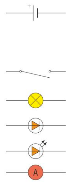
How does one represent an electric field?
For a positively charged object:
What would be different in the diagram if the object was negatively charged?
The arrows would be pointing inwards.
What happens if the two objects are oppositely charged?
Electrons in the air molecules between the two objects experience a force towards the positive object.
What if the field is too strong?
Sparking happens because some electrons are pulled out of air molecules by the force of the field. These electrons hit other air molecules and knock electrons out of them, creating a sudden flow of electrons between the two charged objects.
Like charges… Unlike charges… ?
Like charges repel.
Unlike charges attract.
What are circuit diagrams used for?
They show you how the components in a circuit are connected together.
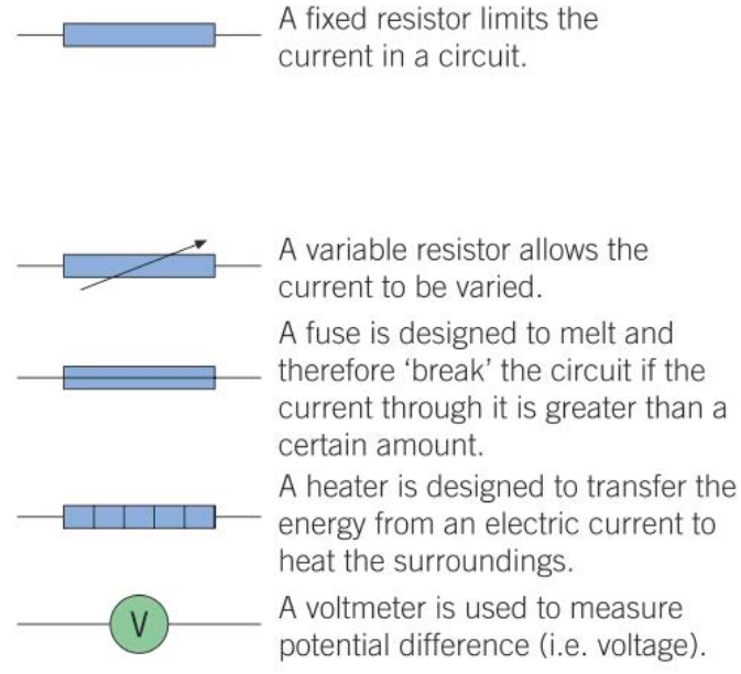
What do these symbols stand for and what do the components do?
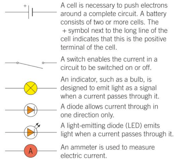
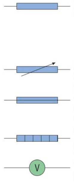
What do these symbols mean and what do the components do?
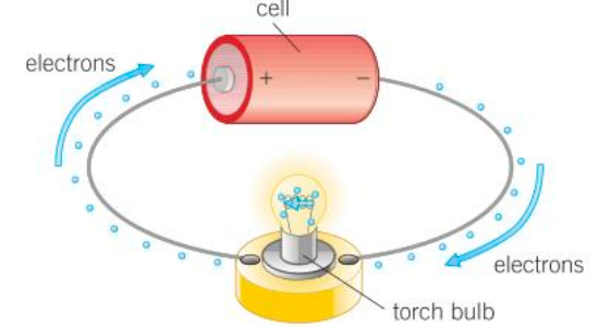
What is an electric current?
A flow of charge.
What is the size of an electric current?
The rate of flow of electric charge/ The flow of charge per second.
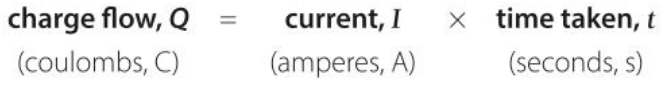
What is the equation for charge flow?
How is current measured?
Using an ammeter.
Ammeters are connected in series with the component of which’s current you’re trying to measure so the current through them is the same.
How is potential difference/voltage measured?
Using a voltmeter.
A voltmeter is connected in parallel with the component of which’s PD you’re trying to measure.
What is the equation for PD which involves energy and charge?

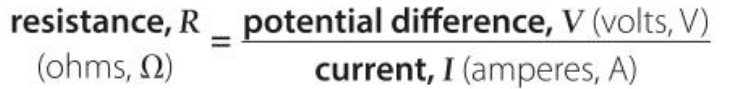
What is the equation for resistance?
Describe current’s proportionality to voltage. What does this mean?
Directly proportional. This means the resistance is constant.
The current through a resistor at constant temperature is directly… ?
The current through a resistor at constant temperature is directly proportional to the potential difference across the resistor.
What is the gradient of a line on a current-voltage graph dependent on?
The resistance of the resistor,
The greater the resistance of the resistor, the less steep the line.
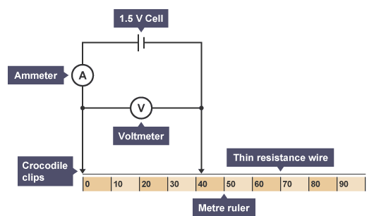
Explain the required practical which investigates how the resistance of a wire depends on its length.
Required Practical -How does the resistance of a wire depend on its length?
Equipment:
1.5V cell
Ammeter
Voltmeter
Crocodile clips
Thin resistance wire
Metre ruler
Wires
Method:
Connect the circuit as shown in the diagram.
Connect the crocodile clips to the resistance wire, 100 cm apart.
Record the reading on the ammeter and the voltmeter.
Move one of the crocodile clips closer until they are 90cm apart.
Record the new readings on the ammeter and the voltmeter.
Repeat the previous step reducing the length of the wire by 10cm each time down to a minimum length of 10cm.
Use the results to calculate the resistance of each length of wire by using R=V/I.
Plot a graph of resistance against length for the resistance wire.
Outcome:
Resistance should be directly proportional to length as the graph should give a straight line through the origin.
Safety:
Do not touch the resistance wire whilst the circuit is connected.
Allow the wire time to cool.
If not followed, the heating of the resistance wire could cause burns to the skin.
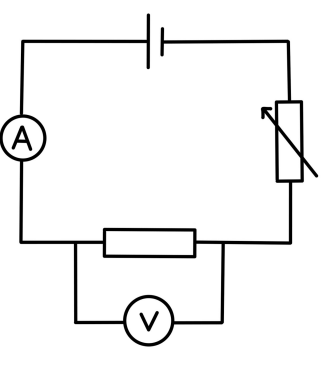
Explain the required practical which investigates different components.
Required Practical - Investigating Different Components.
Apparatus:
Wires
Ammeter
Milliammeter
Voltmeter
12V, 24W filament lamp
Resistor
Diode & protective resistor
Variable resistor
Variable power supply
Method:
Construct the circuit as shown in the diagram.
Set the variable power supply or variable resistor to the lowest setting for potential difference.
Record the current and voltage over the resistor.
Increase the current from the power supply by 2V and repeat your readings.
Change the resistor to a filament lamp and repeat the experiment.
Change the filament to a diode and protective resistor (to restrict high current flowing through the diode), ensuring the diode is in the correct direction to allow the flow of current through. Change the ammeter to a milliammeter, since the current measured will be smaller than for the other components.
Plot a graph of current against voltage for each component.
Expected Results:
The resistor should have a graph with a straight line through the origin. It should follow Ohm’s law (resistance is constant).
The filament lamp and diode should have a graph which isn’t linear as they’re non-ohmic conductors.
Safety Precautions:
Wires and components may become hot after a current passes through. Allow to cool before handling.
Disconnect the power supply when not taking readings to prevent overheating.
Too high a voltage may damage components and cause excessive heating. Switch your circuit off if you think the voltage is too high.
What makes a component an ohmic conductor?
If the current is directly proportional to the voltage.
What increases along with current?
Resistance
Why does the resistance of a filament lamp increase as the filament temperature increases?
The atoms in the metal filament vibrate more as the temperature increases. This means they resist the passage of the electrons through the filament more. The resistance of any metal increases as its temperature increases.
What happens to the current if PD is reversed?
The current is also reversed.
Does direction matter if resistance is the same for the same current?
No, resistance is the same for the same current, regardless of its direction.
Why does a filament light bulb sometimes fail when it switches on?
Because resistance is low when the bulb is off, a big current passes through it when you switch it on. If the current is too big, it burns the filament out.
What one direction does the current though the diode flow in?
The forward direction.
What type of conductor is a diode? Why?
A non-ohmic conductor because the current running through it is not directly proportional to the voltage running through it.
What is the current in the reverse direction through a diode? What does this mean for its resistance?
Virtually zero. This means that the diode’s resistance in the reverse direction is a lot higher than its resistance in the forward direction.
What is an LED?
A light-emitting diode is a diode that emits light when a current passes through it in the forward direction.
What is a thermistor?
A temperature-dependent resistor which increases in resistance if its temperature decreases, and vice-versa.
What is an LDR?
A light-dependent resistor which’s resistance decreases if the light intensity increases, and vice-versa.
What is the current through each component in a series circuit?
The same current passes through each component.
What is the total voltage in a series circuit?
The total potential difference in the power supply is shared between the components.
What is the total voltage in a series circuit in terms of cells and batteries?
The total PD of cells in series is the sum of the PD of each cell.
What is the equation for total resistance in a series circuit?

The total resistance of a series circuit is equal to…?
The sum of the resistance of each component.
Why does adding more resistors to a series circuit increase the total resistance of the circuit?
Because the total PD is shared between more resistors, meaning the PD across each of them is less than before. This means the current through the resistors is also less than before, and since the total PD is unchanged, the total resistance is greater. (R=V/I)
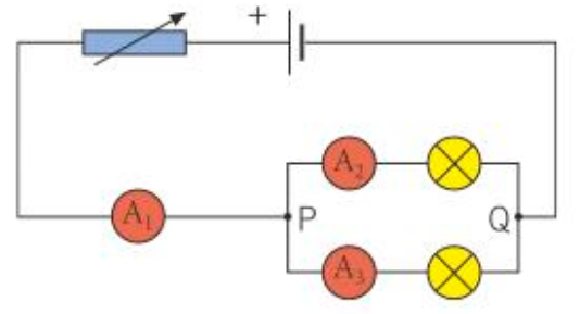
What is the current in series equal to when there is a junction in a circuit?
A1 = A2 + A3
The total current through the whole circuit is the sum of the currents through the separate branches.
For components in parallel, what is the PD?
For components in parallel, the potential difference across each component is the same.
What is the total flow of charge through a parallel circuit? What does this mean?
The total flow of charge is the sum of the flow through each component.
Since the total flow of charge per second is the total current, for components that are in parallel, the total current is the sum of the currents through each component.
The bigger the resistance of a component, the ______ the current through it.
Smaller
What is the equation for current?

What effect does adding more resistors in parallel have? Why?
A decrease in the total resistance because the total PD is the same across each resistor. Therefore, adding an extra resistor in parallel increases the total current entering the combination.
Since R=V/I, the total resistance is less than it was before the extra resistor was added as the current is higher.
The total resistance of two (or more) components in parallel is less than the … ?
The total resistance of two (or more) components in parallel is less than the resistance of the resistor with the least resistance.
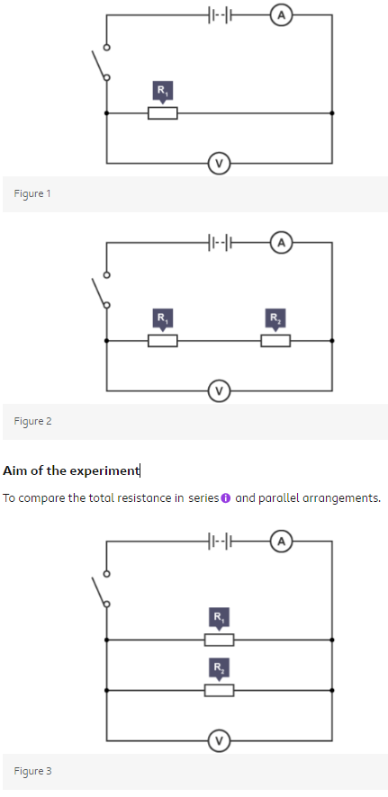
Explain the required practical for investigating resistors in parallel and series.
Required Practical - Investigate Resistor Networks:
Equipment List:
Wires
Ammeter
Resistors
Voltmeter
Switch
Power supply
Method:
Set up the circuit as shown in figure 1, turn the power supply on and close the switch.
Record the voltmeter and ammeter readings and calculate the resistance of the resistor using R=V/I.
Change the resistor and repeat step two to find the resistance of a second resistor.
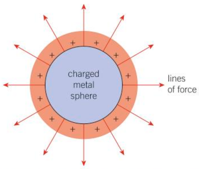
Arrange the two resistors in series as shown in figure 2 and close the switch.
Record the voltmeter and ammeter readings once again and determine the total resistance of both resistors in series using R=V/I.
Arrange the two resistors in parallel as shown in figure 3 and close the switch.
Record the voltmeter and ammeter readings once again and calculate the total resistance of both resistors in parallel.
Outcome:
In series, the resistance of the network is equal to the sum of the two individual resistances.
In parallel, the resistance of the network is less than either of the two individual resistances.
Safety:
Set up the circuit before closing the switch as the heating of wires may cause minor burns.