P2P - Magnetism 3
1/48
Earn XP
Name | Mastery | Learn | Test | Matching | Spaced | Call with Kai |
|---|
No analytics yet
Send a link to your students to track their progress
49 Terms
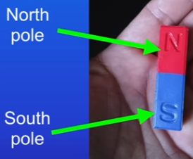
Bar magnet
magnetic forces are strongest at poles of a magnet
bring two magnets close together = exert a force on each other - NS = attract, SS = repel
non-contact force
Permanent vs induced magnet
Permanent produces own magnetic field (bar)
Induced is an object that becomes a magnet when placed in a magnetic field
Induced magnetism always causes a force of attraction and stops being a magnet when seperated
v1 - permanent and induced magnets
Four types of magnetic material
iron, steel (which is an alloy of iron), cobalt and nickel
all can be made into a permanent or induced magnet
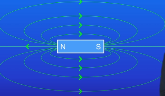
magnetic field and strength
region around a magnet where a force acts on another magnet or on a magnetic material
strength of field depends on distance from magnet
How to find direction of a magnetic field
found using magnetic compass, containing a small bar magnet
place near = plot magnetic field
place compass near N pole. draw cross at N pole of the compass
move compass so S pole is on the cross. draw cross at N
repeat until reaching S pole of bar magnet = complete magnetic field line
connect all dots with a line and show direction of field line with arrow.
Direction is always N to S
Repeat starting at diff points around the N pole of the bar magnet
where line are closer, field is stronger = poles
Magnetic Compass and earths field
contains a small bar magnet
hold the compass away from any magnets, the needle always points in the North - South direction
Tells us that the Earth has its own magnetic field. Due to the earths core
v2 - magnetic fields
Current flowing through wire and compass
what is produced around the wire and how to prove
how magnetic field strength and direction changes
rule to work out magnetic field direction
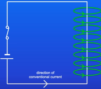
Magnetic field is produced around the wire:
prove by using compass
turned off switch = compass needle aligns with earths magnetic field
turned on switch = compass needle deflects
Strength of magnetic field depends on current size
larger I = stronger field
Magnetic field is strongest closer to the wire
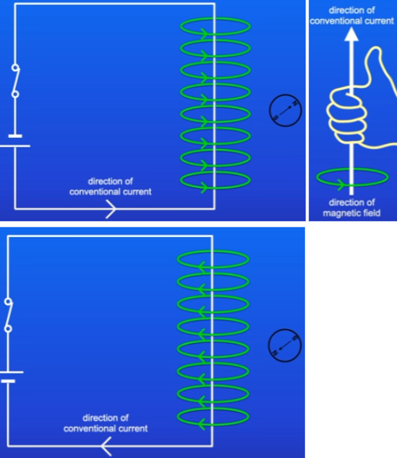
Change current direction = change magnetic field direction = compass deflects in opposite direction
right hand grip rule = thumb shows conventional current direction = fingers are field direction
Another way of increasing magnetic field strength
name of shape
field similarity
rule for field direction
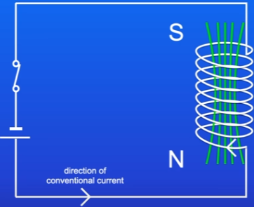
coiling the wire in a circuit = solenoid
turn on current = strong and uniform field inside solenoid, and field around is similar to bar magnet
right hand grip rule = use fingers to wrap in current direction, thumb points N, N is field direction
3 ways to increase strength of magnetic field produced by a solenoid
Increase current size
Increase number of turns of coil
Place iron inside solenoid = iron core
Electromagnet and usefulness
solenoid containing an iron core
extremely useful as we can change strength of magnetic field by changing current size
also can turn on or off
v3 - electromagnets
High voltage circuit dangers and set up
Can be dangerous to use switch to turn these on and off (sparking and electrocution) so:
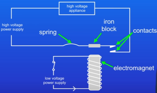
use a relay to turn these on and off, which contains 2 separate circuits:
low voltage circuit containing electromagnet which is safe to switch on/off
replace switch of high voltage circuit with 2 metal contacts
one contact is connected to a spring that keeps the contacts apart
also has iron block next to spring
low voltage circuit off = no current is flowing through EM and theres no magnetic field
high-voltage circuit is turned off since contacts aren’t touching
High voltage circuit stages of circuit
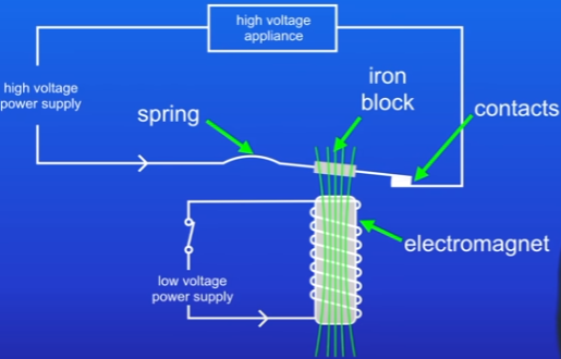
turn on low voltage circuit = current flows around = magnetic field around EM
magnetic field attracts iron block in the high voltage circuit = causes contacts to close and switches on high voltage circuit
switch off low voltage circuit = no magnetic field = contacts spring apart and high voltage is off
Appliance using EM
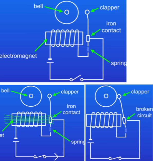
Doorbell:
switch is closed when buzzer is pressed = current flows through circuit = magnetic field is produced by EM
iron contact is attracted to magnetic field = contact moves to field, clapper hits bell
same time, this breaks the circuit = no current = no field = iron contact springs back to original position
now circuit is complete again so current flows and process is repeated
v4 - electromagnetic devices
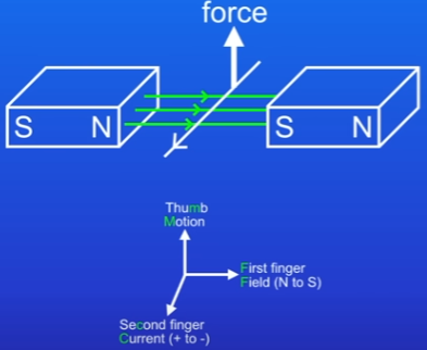
Motor effect
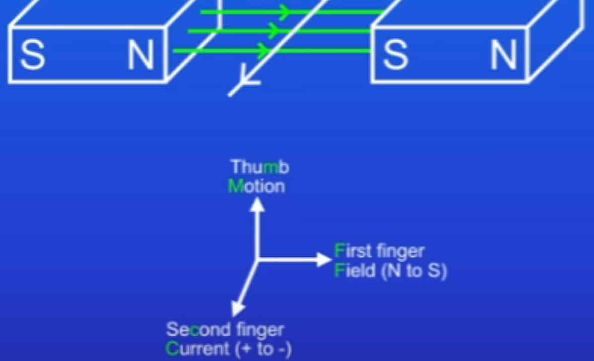
Wire placed into magnetic field between 2 bar magnets
Magnetic field around wire interacts with magnetic field between the magnets = wire experiences force up or down depending on field and current direction
This case upwards = wire moves up
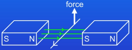
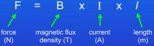
Calculate force from motor effect
applies to a wire at right angles to the magnetic field
magnetic flux density measures strength of magnetic field
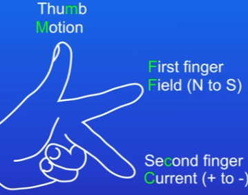
Flemings left hand rule
thumb is motion (direction of force that moves wire)
first finger is field
second finger is current

Conductor parallel to magnetic field
won’t experience force
v5 - motor effect
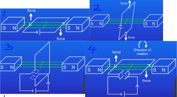
Motor effect - electric motors
2 magnets, north (left) to south (right), current flowing to the right.
As current flows, when reaching S, wire experiences a force down (right side), and when reaching N, wire goes up (left side) = a moment on the left and right side
Loop will rotate in clockwise direction
Once loop is at 90 degrees it stops rotating
imagine loop goes beyond 90, direction of the current travels in the opposite direction than the previous current, which means left is acting downwards and force on right is upwards
these forces push the loop back to the 90 degrees
can solve this problem by switching direction of the current when the loop passes 90
Do this with a split-ring commutator: a split metal ring connected to conducting brushes. Brushes allow the electric current to pass onto the ring.
Current produces a turning force on the motor = forces makes motor rotate clockwise = current is broken for a tiny fraction of a second, but wire keeps turning due to momentum.
Current now switches direction, and the force on the left still acts up, and force on the right still down (same as step 2)
By switching direction of the current, split ring commutator allows motor to keep rotating in same direction
electrical energy → kinetic energy
Motor effect - electric motors diagrams
v6 - electric motor
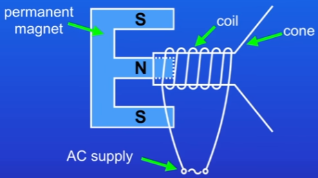
Motor effect in loudspeakers and headphones
Moving-coil loudspeaker is found in speakers on a stereo (headphones are similar but smaller):
Cone with coil of wire wrapped around one end. Coil of wire is connected to an A.C electrical supply. Permanent magnet which goes inside the coil of wire.
As current passes through coil, it generates a magnetic field.
Magnetic field from coil interacts with magnetic field from permanent magnet = they attract or repel each other
This produces a resultant force which causes the cone to move.
When current switches direction, the direction of the forces on the cone reverses = cone moves in and out, generating sound waves.
By changing freq of AC, we change freq that cone vibrates. Higher freq = higher pitch
By increasing current size, we increase amplitude of vibration. Increases volume
v7 - loudspeakers and headphones
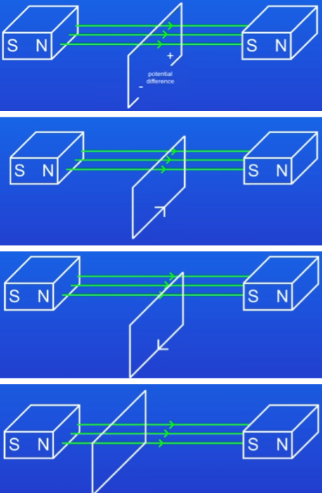
Generator effect - normal wire
when a conductor (metal wire) cuts flux (moves through magnetic field) upwards, a potential difference is induced across the conductor (metal wire).
wire stops moving, then p.d is lost, but if the wire cuts flux downwards, we get a p.d again, but this has a reversed direction = this p.d is called the induced potential
Key points:
if we have a complete circuit, we induce a current and that switches direction when the direction of movement switches
process is the same if the field is moved into a conductor, rather than a conductor being moved into a field
Conditions and relation to motor effect:
whole thing only happens if conductor CUTS FLUX, not if wire is moved back and forth around a field
kinetic energy → electrical energy = reverse of motor effect
The induced potential difference and current are larger if we…
use a stronger magnetic field = magnetic flux density(B)
move the wire more rapidly
shape the wire into a coil (greater number of turns on coil = longer)
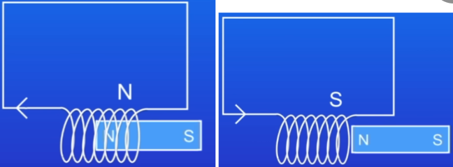
Generator effect - coiled wire
magnet moving in and out of a coil of wire also makes induced current.
direction of current changes when direction of movement changes OR if we flip the poles
this induced current creates its own magnetic field, which opposes movement of the magnet
insert N pole into the coil = that end of the coil also becomes a N pole = this repels the magnet = harder to push magnet in
pull N out = that end of the coil becomes S = attracts the magnet, so harder to pull out
since induced current makes it harder to move the magnet, we are doing work OR transferring energy from the movement of the magnet, into the movement of the current
v8 - generator effect
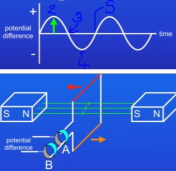
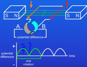
Alternator stages and graph
Alternator is a coil of wire rotating in a magnetic field:
Coil is connected to 2 metal rings called commutators, which allow current to pass out of coil.
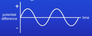
A p.d is induced when the wire passes through the magnetic field
graph shows how the p.d changes
red side of the wire always connects onto ring A, and orange side always connects onto ring B
the max p.d is when the coil is horizontal. At this point, the wire is sweeping directly through the magnetic field lines at the fastest possible rate.
red side moving down and orange side moving up
coil is vertical = p.d is zero, since coil is moving parallel to the field. At this point, the coil is not cutting through the magnetic field lines.
coil continues around = get a p.d again but with reversed direction, since the 2 sides of the coil are now moving in a different direction to before
red side moving up and orange side moving down
again coil is vertical = p.d is zero, since coil is moving parallel to the field and not cutting flux
since two sides of the coil are attached to two different rings, and alternator produces an alternating p.d and alternating current
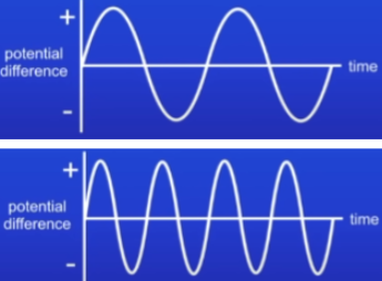
How to increase size of current, freq and p.d with alternator
increase strength of magnetic field = increase size of AC
increase size of AC if we increase turns on the coil or area of the coil
increase rotation speed of coil = increase both the size and freq of AC
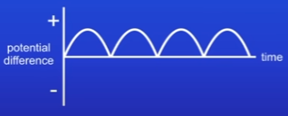
Dynamo stages and graph
produces direct current
has a split-ring commutator with 2 sides separated by a gap (A,B)
Side of coil moving down is connected to A of split-ring commutator. side of the coil moving up is connected to B. Start with red on left (down) orange on right (up).
Since coil is cutting through magnetic field lines, a p.d and current are induced.
Coil is vertical = moving parallel to magnetic field so p.d is 0.
Now coil has moved around, orange on left (down) red on right (up). But side of coil moving down is still connected to A of split-ring commutator, and side moving up is still connected to B.
Therefore direction of p.d and current don’t reverse when coil rotates = Direct current
graph shows how p.d changes
we get 2 peaks for each full rotation of coil - since each side of coil cuts flux twice during each cycle of rotation. Once passing down, once up.
v9 - Alternator and dynamo
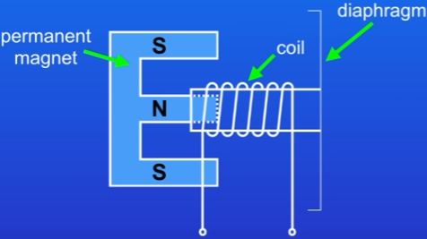
Moving-coil microphone
Very similar to moving-coil loudspeaker:
coil of wire attached to a thin sheet of plastic, called a diaphragm, end of coil of wire sits over a permanent magnet
when soundwaves hit the diaphragm, they cause it to vibrate
coil of wire moves in and out through the magnetic field = induces a p.d across the ends of the wire
p.d switches direction as coil moves back and forwards through magnetic field. Frequency of the changing p.d is same as freq of the sound waves.
Changing pattern of p.d is passed through an amplifier and then into a moving-coil loudspeaker = massively increases volume
v10 - the microphone
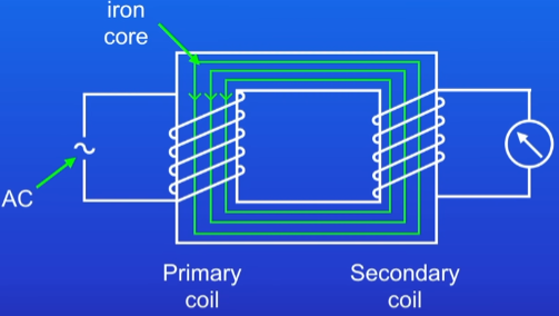
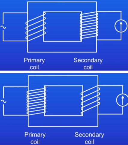
Transformer - 100% efficient
2 coils of wire wrapped around iron (easily magnetised) core- primary and secondary are completely separate
primary coil is connected to AC. As current flows through primary, it generates a changing direction magnetic field.
This magnetic field is transmitted along iron core and passes through secondary coil = coil induces a p.d
Primary and secondary has same number of coil turns = p.d is the same in each. Only true if transformer is 100% efficient (no energy wasted in the transformer). In practise, transformers aren’t 100% efficient
Transformer key points
iron core increases the strength of the magnetic field
transformers only work with AC since we need a changing magnetic field to induce a p.d
DC produces a constant magnetic field = doesn’t work in transformers
Transformer - unequal coils
Step-up transformer:
more turns in secondary coil than primary coil = p.d induced in secondary coil will be greater than p.d in primary coil
this is called a step-up transformer, since it steps-up the p.d
if turns double in secondary, the p.d doubles in the secondary
Step-down transformer:
exact opposite of step-up
v11 - transformers
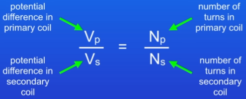
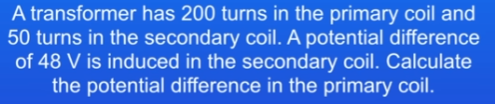
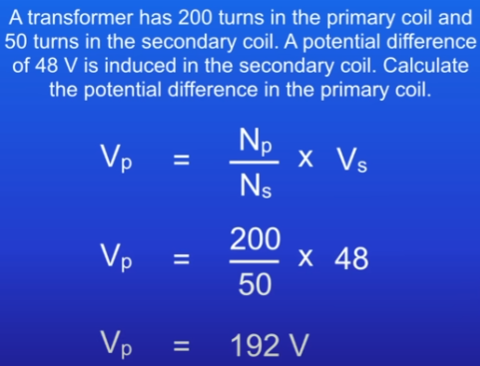
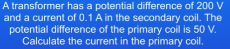
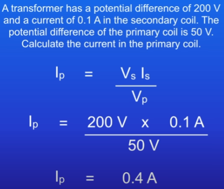
Finding p.d of transformer coils - eq
Conservation in transformers and eq
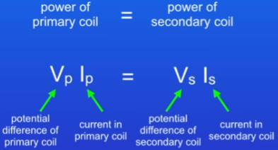
power must be conserved
power of primary coil = power of secondary coil
only applies if the transformer is 100% efficient (no energy wasted). not true in practise, only calcs
National grid - issues and solution
Electrical power is transmitted from power stations to homes through high-voltage cables
power = current x p.d
To transmit a large amount of power, either use a large current or a large voltage
Power is wasted in the transmission cables as heat and this amount depends on square of the current (I²)
Large current in transmission cables = huge amount of power wasted as heat
So instead use a large p.d
National grid stages
Electricity from power station is passed through a step-up transformer. Increases p.d to 400kV.
Electrical power is transmitted down high-voltage cables.
Passed through a step-down transformer. Decreases p.d to 230V for homes
Transformers massively reduce power wastage in National Grid
v12 - transformer calculations