MI 237 - Unit 1
1/68
There's no tags or description
Looks like no tags are added yet.
Name | Mastery | Learn | Test | Matching | Spaced | Call with Kai |
|---|
No study sessions yet.
69 Terms

A
transmission
B
absorption

C
scatter
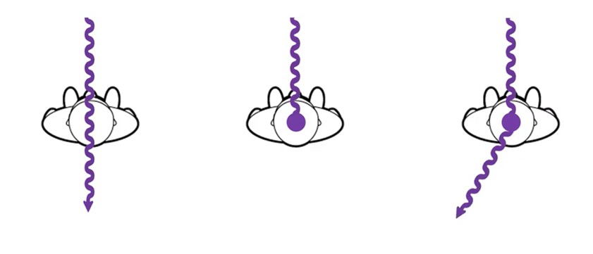
Compton Scattering
energy is >20kV
ionization of outer shell
scattered photon - yes
free electron - yes
dose is minimal - significant to patient and most significant to radiographer
probaility : as kVp increases, probability decreases, but it is more common at higher kVps than photoelectric

what is happening in this image
compton scattering
what does scatter do to an image
adds unwanted noise
decreases image contrast levels
3 factors that impact scatter production
part thickness
field size
kVp
part thickness
increasing patient size or body part increases scatter
more matter more scatter
field size
increasing field size exposed increases scatter
more matter = more scatter
kVp
increasing kVp decreases the photoelectric and compton interactions that happen
there are more compton interactionsthat happen over photoelectric
the scattered photon has higher remaining energy when higher kVp was used
increasing kVp = increases scatter
2 factors to help scatter control
beam-restricting devices
radiographic grids
beam restricting devices
AFFECTS SCATTER PRODUCTION
decreases the x-ray beam field size and the amount of tissue irradiated, reducing the amount of scatter produced in the patient
radiographic grids
AFFECTS SCATTER CLEAN UP AFTER PRODUCTION
used to improve radiographic image quality by absorbing scatter radiation that exits the patient, reducing the amount of scatter reaching the image receptor
beam restriction purpose
limits patient exposure
reduces scatter production
increasing beam restriction
decreases patient dose
decreases scatter produced in the patient
decreases scatter reaching the IR
increases radiographic contrast
types of beam restricting devices
aperture diaphragm
cones and cylinders
collimators
automatic collimators (PBLs)
lead masks
aperture diaphragm definition
a flat piece of lead (diaphragm) that has a hole (aperture) in it and is placed directly below the x-ray tube window
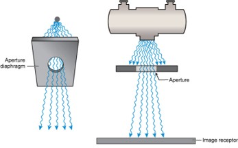
what is this
aperture diaphragm
cones and cylinders definition
an aperture diaphragm with an extended flange attached to it
almost always made to produce a circular projected field

what is A
cylinder
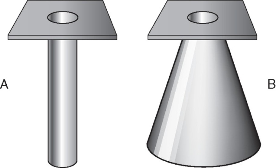
what is B
cone
collimators
located immediately below the tube window
2 sets of lead shutters
first (entrance shutter)
limits the field size similar to aperture diaphragm
second (adjustable shutters)
longitudinal and lateral “leaves” or “blades”
limits off-focus radiation (extrafocal radiation)
x-rays created anywhere outside of focal spot
x-rays not aligned with regular beam
adds noise to the image
collimators are equipped with
a white light source and a mirror to project a light field onto the patient which indicated exposure area
an x-ray field measurement guide in case of light failure
a plastic template with crosshairs to indicate centering
automatic collimators are also known as
positive beam-limiting (PBL) device
what do PBLs do
automatically limits the size and shape of primary beam to the size and shape of the IR
lead blockers/masks
similar to aperture diaphragm
limited to that shape and size
cut out to shape of body part
who invented the first grid
Gustav Bucky
Gustav Bucky designed a
cross hatched grid
Hollis-Potter design is a
grid with linear strips only, thinner strips, Potter-Bucky diaphragm moved during grid exposure to blur grid lines
radigraphic grids are
very thin lead strips that absorb scatter from the patient before it can reach the IR
it is placed between patient and IR
typrical grids use
part thickness > 10cm
kVp above 60
strips of the grid are made of
lead
interspace material of grids are made of
aluminum or plastic
grid dimensions include
height (H)
thickness lead strip (T)
distance between strips (D)
grid ratio is
height of grid/distance between lead strips
grid construction is describe by
grid ratio and grid frequency
grid ratio ranges from
5:1 to 16:1
as the ratio increases so does the efficiency of scatter clean up and the image quality/contrast
grid frequency is
the number of lead lines per unit length (cm, mm, inches)
ranges from 60-110 lines/inch
most common grid frequency
85-103 LPI
linear grid pattern
lead lines run in only one direction
most popular
allows angulation of central ray along the length of lead strips because only absorbs scatter in one direction
crosses grid pattern
lead lines run at right angles to one another
most effective at absorbing scatter
difficult to use
must center perfectly and cannot angle central ray
non-focused/parallel grid
lead lines run parallel to one another
focused grid
lead lines are angled to match the angle of divergence of the primary beam
most common
allows more transmitted photons to reach the IR
can only be used at specific SID’s so that the divergence of beam matches lead strips
convergent point/convergent line
determines the focal distance of a focused grid
focal distance (grid radius)
distance between the grid and the convergent line or point
focal range
the recommended range of source to image receptor distances (SIDs) that can be used with a focused grid
multi-focus grids
grids with a wide range of focal distances
lower grid ratios
shorter height strips
decreased strip angles
tech doesn’t have to change out
not as precise scatter clean up as focused grid at one distance
stationary , nonmoving grids
grid cap
contains a permanently mounted grid and allows the IR to slide in behind it
wafer (slip on) grid
matches the size of the cassette and is used by placing it on top of the IR
grid cassette
IR that has a grid permanently mounted to its front surface
moving or reciprocating grids (oscillating)
potter-bucky diaphragm
located directly below the radiographic tabletop and just above the tray that holds the IR
grid motion controlled electrically by the x-ray exposure switch
grid moves slightly back and forth in a lateral direction over the IR during the entire exposure
grid conversion formula
used to maintain receptor exposure with changing grid ratio
mAs1/mAs2 = GCF2/GCF1 OR mAs2 = (mAs1 x GCF2)/GCF1
grid cut off
a decrease in the number of transmitted photons that reach IR because of some misalignment of the grid
5 types of errors that can result in grid cut off
off-level
off-angle
off-center
off-focus
upside-down
grid lines may also occur
off level error
can affect focused and parallel grids
grid not flat
central ray not perpendicular to grid strips
loss of exposure across entire image
off angle error
affects focused and parallel grids
beam is angled across/against the lead strips
loss of exposure across entire image
off center error
only affects focused grid
occurs when the central of the x-ray beam is not aligned from side to side with the center of a focused grid
loss of exposure across entire image
off focus error
only affects focused grids
occurs when using an SID (greater than or less than) outside of the recommended focal range
loss of exposure at the periphery of the image (outer edge only)
upside down error
only affects focused grids
focused grid is placed upside down on the IR, resulting in the grid lines going opposite the angle of divergence of the x-ray beam
significant loss of exposure on outer edges only
grid lines - reciprocating grid
grid lines can be visible if
reciprocating grid fails to move
exposure time is too short for grid to move
grid lines - stationary grids
grid lines can become visible if useful beam is absorbed by lead strips
grid usage
for parts 10 cm or larger
60 kVp or higher
grid selection involves consideration
contrast improvement
patient dose
likelihood of grid cutoff
virtual grids
use complex algorithms to analyze and correct images
*still need a real grid for some larger body partx
virtual grids benefits
can allow for lower mAs to be used as no grid is used = lower pt dose
less repeats
digital post processing allows for real time corrections
virtual grid challenges
high costs
large datasets needed for machine learning
integration complexity
air gap technique
provides another way for limiting the scatter reaching the IR
based on increased OID
acts like a grid
large OID
allows time for scattered photons to diverge before they reach the IR
less scatter = less grays
increased contrast
air gap disadvantages
reduces quantity/receptor exposure
creates size distortion