Gears (skip yung sa measurements pang akin yun)
1/137
There's no tags or description
Looks like no tags are added yet.
Name | Mastery | Learn | Test | Matching | Spaced |
|---|
No study sessions yet.
138 Terms
Gears
are toothed members which transmit power / motion between two shafts or between a shaft and a slide by meshing without any slip.
positive drives
gear drives are also called
Pinion
In any pair of gears, the smaller one is called
Gear (Bull gear)
In any pair of gears, the larger one is called
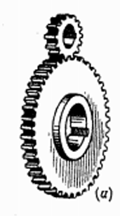
Spur gear
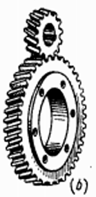
Helical
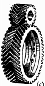
Double helical gear or Herringbone gear
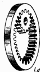
Internal gear
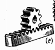
Rack and pinion
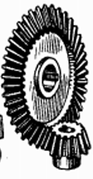
Straight bevel gear
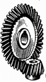
Spiral bevel gear
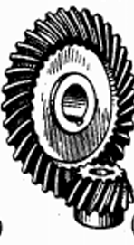
Hypoid bevel gear
Spur (straight cut) gears
are widely used in parallel shaft applications, such as transmissions, due to their low cost and high efficiency. The design allows for the entire gear tooth to make contact with the tooth face at the same instant.
Spur (straight cut) gears
this type of gearing tends to be subjected to high shock loading and uneven motion. Design limitations include excessive noise and a significant amount of backlash during high-speed operation.
Helical gears
differ from spur gears in that their teeth are not parallel to the shaft axis; they are cut in a helix or angle around the gear axis. During rotation, parts of several teeth may be in mesh at the same time, which reduces some of the loading characteristics of the standard spur gear.
Herringbone gears
are an improvement over the helical gear design. This gears are actually double helical gears with teeth angles reversed on opposite sides. This causes the thrust produced by one side to be counterbalanced by the thrust produced by the other side. The two sets of teeth are often separated at the center by a narrow gap for better alignment and to prevent oil from being trapped at the apex.
Herringbone gears
are capable of transmitting large amounts of power and are frequently used in power transmission systems. These gears are best suited for quiet, high-speed, low-thrust applications where heavy loads are applied. Large turbines and generators frequently use these gears because of their durability.
Internal gears
are used for transmitting power between two parallel shafts. In these gears, annular wheels have teeth on the inner periphery which makes the drive very compact. In these drives, the meshing pinion and annular gear are running in the same direction. Their precision rating is fair. They are useful for high load and high-speed application with high reduction ratio.
Rack
is a segment of a gear of infinite diameter and the tooth profile can be spur or helical. This type of gearing is used for converting rotary motion into translatory motion or vice versa
Rack and pinion
Typical examples of ___________ applications are for lathe carriage drive mechanisms and radial drilling machine spindle movement.
Bevel gears
(straight and spiral cut) transmit motion between shafts that are at an angle to each other. Primarily found in various types of industrial equipment as well as some automotive applications (differentials), they offer efficient operation and are easy to manufacture.
Spiral gears
are also known as crossed helical gears; they have a high helix angle and transmit power between two non-intersecting non-parallel shafts. Their point of contact comes under the conditions of considerable sliding velocities; hence, their precision rating is poor. They are used for light load and low speed application such as instruments, sewing machines etc.
Hypoid gears
are a form of bevel gears designed to operate on non-intersecting axes. They offer improved efficiency and higher ratios over traditional straight bevel gears. Commonly found in axle differentials, these gears are used to transmit power from the driveline to the axle shafts.
Worm gear
sets employ a specially-machined __ that conforms to the arc of the driven gear. This type of design increases torque throughout, improves accuracy and extends operating life. Primarily used to transmit power through non-intersecting shafts, this style of gear is frequently found in gear reduction boxes as they offer quiet operation and high ratios (as high as 100:1). Downfalls with this type of gear set are its efficiency, high price per HP and low ratios (5:1 minimum).
Planetary gear
such as those found in automatic transmissions, provide the different gear ratios needed to propel a vehicle in the desired direction at the correct speed. Gear teeth remain in constant mesh, which allows for gear changes to be made without engaging or disengaging the gears, as is required in a manual transmission. Instead, clutches and bands are used to either hold or release different members of the gear set to get the proper direction of rotation and/or gear ratio.
Addendum circle
The imaginary circle drawn through the tips of the gear teeth, concentric with the pitch circle. It defines the outermost boundary of the gear teeth
Dedendum circle
The imaginary circle drawn through the bottoms of the gear tooth spaces, also known as the root circle. It is located inside the pitch circle.
Pitch circle
an imaginary circle that represents the location where two mating gears effectively contact and roll without slipping. It is the fundamental reference circle for gear calculations.
Pitch diameter (D)
is the diameter of the pitch circle. This circle is theoretical circle upon which all computations are made.
Face Width
The width of the gear tooth measured parallel to the gear’s axis. It determines the surface area of contact between meshing teeth.
Pitch surface
The imaginary surface generated by the pitch circle. For spur gears, it is cylindrical; for bevel gears, it is conical
Pitch point
is the point P which divides the line of centers of a pair of gears into two parts proportional to the number of teeth.
Pitch point
is the point of tangency on the center line of the pitch circles.
Working Depth (Hw)
The radial distance through which the tooth of one gear actually engages with the tooth of the mating gear. It is equal to the sum of the addenda of the two gears.
Whole Depth (HT)
The total depth of the gear tooth space, measured radially from the addendum circle to the dedendum circle. It is equal to the addendum plus the dedendum.
Circular pitch (Pc)
is the distance from the center of one tooth the center of the next tooth, measured on the pitch circle. This is, of course, equal to the distance from any point on a tooth to the corresponding point on the next tooth. It is also equal to the tooth thickness plus the space width.
Diametral pitch (Pd)
is the term ordinarily used to designate the tooth size; it is equal to the number of teeth divided by the diameter of the pitch circle.
This indicates that the product of PcPd=π
Center to Center distance (CC)
is the distance between the center of the pitch circles of two gears in mesh.
Module (M)
is used with SI units and is the ratio of the pitch-circle diameter of a gear in millimeters to the number of teeth
Clearance (cl)
The radial distance between the top of a tooth on one gear and the bottom of the mating gear’s tooth space. It prevents interference during meshing
Face
The portion of the tooth surface lying above the pitch surface and between the addendum circle and the pitch circle
Flank
The portion of the tooth surface lying below the pitch surface and between the pitch circle and the dedendum circle.
Acting Flank
The specific part of the flank that is in actual contact with the tooth of the mating gear during operation.
Fillet
The curved transition at the base of the tooth profile that connects the tooth flank to the bottom land. It reduces stress concentration.
Fillet radius, rf
made equal to the clearance when gear teeth are drawn. However, the actual shape of the fillet curve on a gear will depend on the method used for cutting the teeth.
Tooth thickness (T)
The width of a single tooth measured along the pitch circle
Space width or tooth space (S)
The width of the gap between two adjacent teeth, measured along the pitch circle.
Backlash (BL)
is the difference between the space width on a gear and tooth thickness on the mating gear measured along the pitch circles.
Bore
the diameter of the hole in a sprocket, gear, bushing, etc.
Top land
The flat surface at the very top of a gear tooth
Bottom land
The flat surface at the very bottom of the gear tooth space (root)
Crowning
A modification that results in the flank of each gear tooth having a slightly outward bulge in its center area.
Gullet
space between two teeth of a sprocket or gear.
Hub
a shoulder or flange protruding from the side of a sprocket or gear. These provide width to a part, which is used, for mounting the part on a shaft.
Hub Style
indicates the configuration of the hubs on a sprocket or gear. Type `A' indicates that the part has no hub; Type `B' indicates a hub on one side only and Type 'C' indicates a hub on both sides of the part.
Line of Action
the point of contact for any two teeth is always along this line
if friction if neglected between the contacting tooth surfaces, then the force which the driving gear exerts on the driven would be along this line
is the common tangent to the base circles of two gears in mesh.
Pressure Angle
the angle which the line of action makes with a perpendicular to the line of centers
is constant for involute gears, and are standardized by gear manufacturers with values of 14.5, 20, 22.5, and 25 with the 20, 22.5 and 25 being the most frequently applied
Plain Bore
This term is used to indicate that the center hole in a sprocket or gear has no keyway, set screw(s), bushing or any other type of machined preparation for shaft mounting.
Pinion
The smaller gear in a pair of meshing gears.
Bull Gear
The larger gear in a pair of meshing gears, often driven by the pinion
Miter Gears
A type of bevel gears with equal numbers of teeth and shafts intersecting at right angles (90°), resulting in a 1:1 gear ratio.
Step Down Drive
a condition that results when the pinion is the driver, such that the output speed decreases and the torque increases.
Step Up Drive
a condition when the gear is the driver, this results with the increase in output speed and the decrease in torque.
Idler
a component in a power transmission system, which simply turns on its shaft without performing any ratio reduction or power functions.
Keyway
a slot cut into both the bore of a sprocket or gear and the shaft onto which the part will be mounted
A square, steel `key'
(straight or tapered) is inserted between the shaft and the sprocket or gear, allowing power to be transmitted between the two components.
Set Screw
a socket head screw, which is screwed tight against a key or shaft in order to fix a sprocket or gear on that shaft with pressure and friction.
Lead
is the axial advance of a helix for one complete turn, as in the threads of cylinder worms and teeth of helical gears.
Interference
a condition where gear movement is hindered by an obstruction between the tip of the tooth of one gear and the flank of a mating gear. This commonly occurs when a small gear mates with a much larger one.
Gear Train
An arrangement of two or more gears used to transmit motion and torque between shafts
Hobbing
is a machining process for making gears, splines, and sprockets on a machine, which is a special type of milling machine. The teeth or splines are progressively cut into the workpiece by a series of cuts made by a cutting tool called a hob. Compared to other gear forming processes it is relatively inexpensive and quite accurate. It is the most widely used gear cutting process for creating spur and helical gears.
Hob
A cylindrical cutting tool with helical cutting edges, used on a hobbing machine to cut gear teeth into a gear blank. progressively cut teeth or splines into the workpiece by a series of cuts
BHN – Brinell Hardness Number
, a measure of the hardness of a material such as steel, measured on the Brinell scale
Carburizing
a heat treating process, which allows the surface of a low carbon steel gear or sprocket to be hardened to high hardness but to only a shallow depth. This process is usually applied "all over" or to the entire surface of the part.
Concentricity
a condition where two diameters share a common center.
Eccentricity
a condition where deviations from theoretical or perfect concentricity occurs.
AGMA (American Gear Manufacturers Association)
A professional trade organization based in the United States that develops and publishes standards for the design, manufacturing, and application of gears and gear-related products. It also provides technical education, hosts industry events, and works to advance gear technology and quality worldwide.`
pitch line velocity, V
is the linear velocity of the pitch point of two mating gears
pitch line velocity, V=
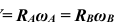
angular velocity ratio rV,
is the ratio of the angular speed of the driver gear to the angular speed of the driven gear and is equal to the number of teeth on the driven divided by the number of teeth on the driver, this is also equal to the ratio of the diameters of their pitch circles. That is, the two gears when turning will have the same ___________ as two rolling cylinders of diameters DA and DB.
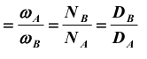
angular velocity ratio rV=
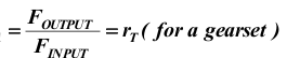
torque ratio, rT
is the ratio of the output torque to the torque input of the driver.
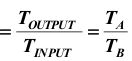
torque ratio, rT=
mechanical advantage mA
is a useful and dimensionless parameter that is used to evaluate the quality of linkage designs
mechanical advantage mA=
gear ratio rG
is the ratio of the larger to the smaller number of teeth on a pair of gears.

gear ratio rG=
involute of a circle
The form of the curve most commonly given to gear teeth is that known as the.
Teeth property constructed with this curve will conform to the law of gearing
base pitch (PB) (normal pitch)
is defined as the distance from a point on one tooth to the corresponding point on the next tooth measured along the base circle. It is also the normal distance between the corresponding sides of two adjacent teeth as shown in the center of the figure.
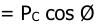
base pitch, PB=
Fundamental Law of Gearing
Requires that the angular velocity ratio between the gears in a gearset remain constant throughout the mesh, to conform to this the diametral pitch for both gears must be the same.
Law Governing the Shape of the Teeth
the line drawn from the pitch point to the point where the teeth are in contact must be perpendicular to a line drawn through the point of contact tangent to the curves of the teeth; that is, the common normal to the tooth curves at all points of contact must pass through the pitch point.
True clearing curve
If the flanks are extended until they join the root line, a very weak tooth will often result. To avoid this, a fillet is used which is limited by the arc of a circle connecting the root line with the flank and lying outside the actual path of the end of the face of the other gear. This actual path of the end of the face is called the
arc of approach
is the arc on the pitch circle where the tooth profile cuts the pitch circle when a pair of teeth first comes in contact until they are in contact at the pitch point.
arc of recess
is the arc of the pitch circle from contact at the pitch point until where the tooth profile cuts the pitch circle when the pair of teeth comes out of contact
arc of action
must never be less than the circular pitch, for, if it were, one pair of teeth would cease contact before the next pair came into contact.
angle of approach
is the angle on the pitch circle where the tooth profile cuts the pitch circle when a pair of teeth first comes in contact until they are in contact at the pitch point.
angle of recess
is the angle of the pitch circle from contact at the pitch point until where the tooth profile cuts the pitch circle when the pair of teeth comes out of contact.
angle of action
is equal to the angle of approach plus the angle of recess.
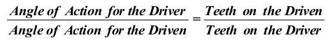
Since the arcs of action on both gears must be equal, the angles of action must be inversely proportional as the radii, and therefore to the number of teeth,