Lesson 7: Combinational Logic Circuits
1/35
There's no tags or description
Looks like no tags are added yet.
Name | Mastery | Learn | Test | Matching | Spaced |
|---|
No study sessions yet.
36 Terms
Combinational Logic Circuit
Consists of logic gates whose outputs at any time are determined directly from the present combination of inputs without regard to previous inputs.
It does not use any memory.
It has no storage or clock elements
Built using logic gates
Perform data processing operation such as arithmetic and logical function
Characteristics of Combinational Circuits:
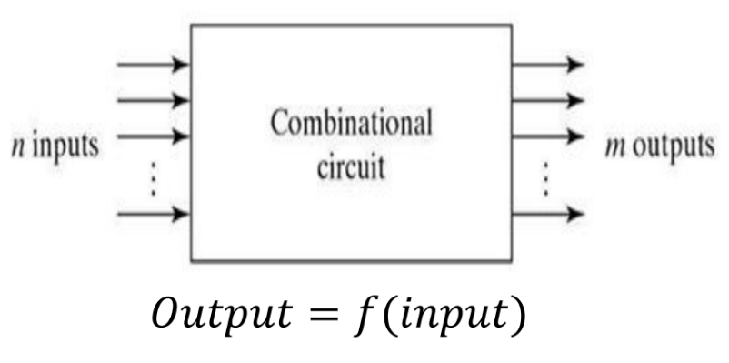
Block Diagram of Combinational Ckt:
Logic Function
It is a Boolean expression that defines the output of a circuit with a given set of inputs.
Truth Table
_________ defines the output of a circuit in tabular form for all possible combinations of inputs.
Logic Diagram
_________ is a graphical representation of a circuit showing the connections of each logic gate.
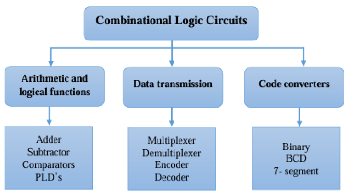
Adders
Comparators
Encoders
Decoders
Multiplexers
Demultiplexers, and
Code converters (such as binary and BCD).
Common combinational logic circuits have specific applications such as:
Half Adder
Full Adder
Half Subtracter
Full Subtracter
Parallel Adder
BCD Adder
Magnitude Comparator
Decoder
BCD to Decimal Decoder
Encoder
Multiplexer
Demultiplexer
Combinational Logic Circuits Examples:
MEMORIZE IT!!
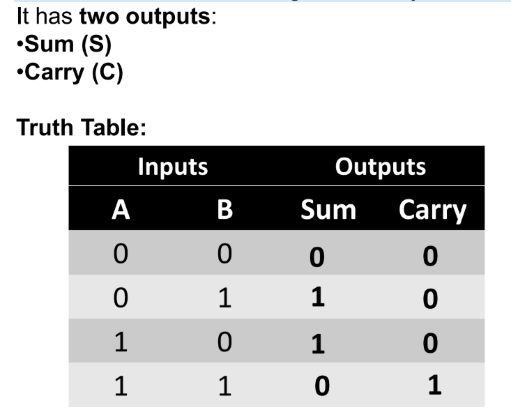
Half Adder
A _________ adds two single-bit binary numbers (A and B).
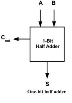
Block Diagram of Half Adder:
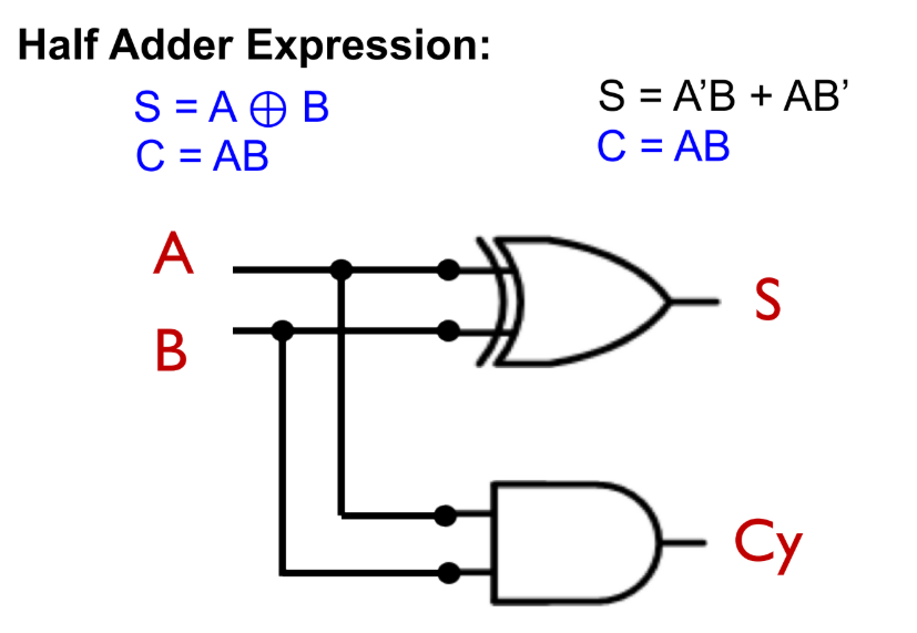
Half Adder Ckt:
Full adder
A _________ is simply a half adder that takes in a carry bit from another section
It is usually a single stage in a cascade of adders used to add large numbers.
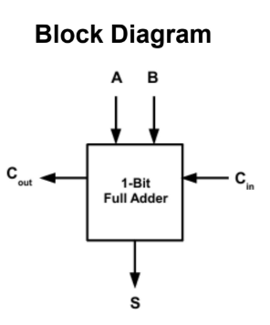
Full Adder Block Diagram:
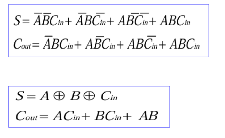
Full Adder Expression:
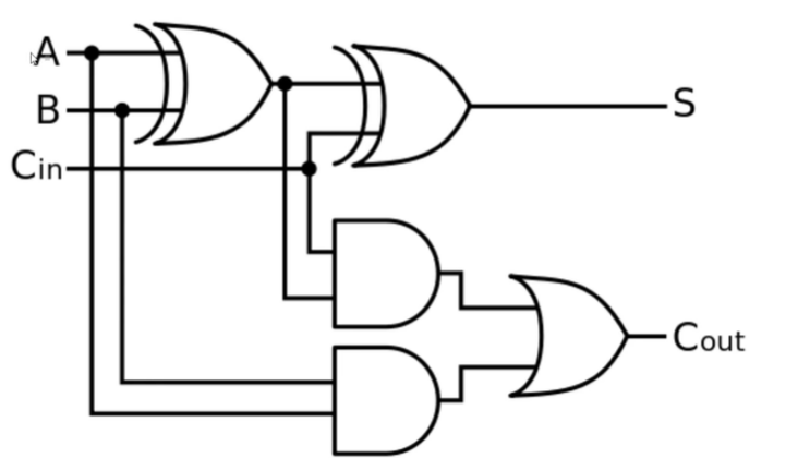
Full Adder Ckt:
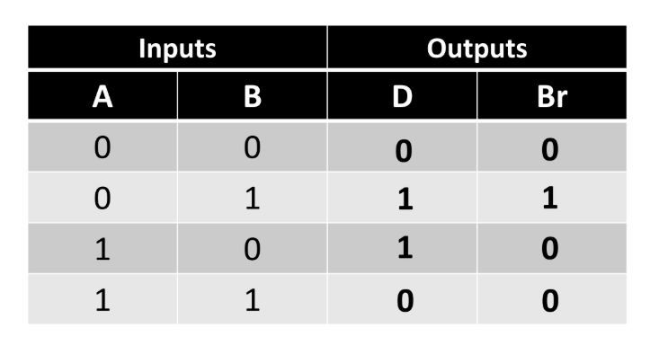
Half Subracter
It subtracts 2 bits mathematically.
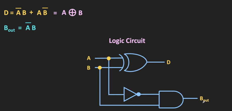
Half Subracter Ckt:
Full Subracter
It subtracts 3 bits mathematically.
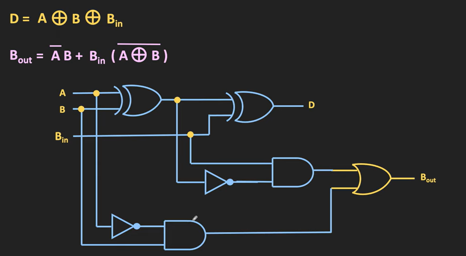
Full Subracter Ckt:
Binary Parallel Adder
A _________ is a digital circuit that performs binary addition on two binary numbers simultaneously (in parallel) — meaning that all bits are added at the same time, not one after another.
Look-Ahead Carry Generation (Carry Look-Ahead Adder or CLA)
It is a fast binary addition technique used to overcome the delay problem of ripple carry adders (like the binary parallel adder).
It is a method of determining carry outputs directly from the input bits, without waiting for carry propagation from the previous adder stages.
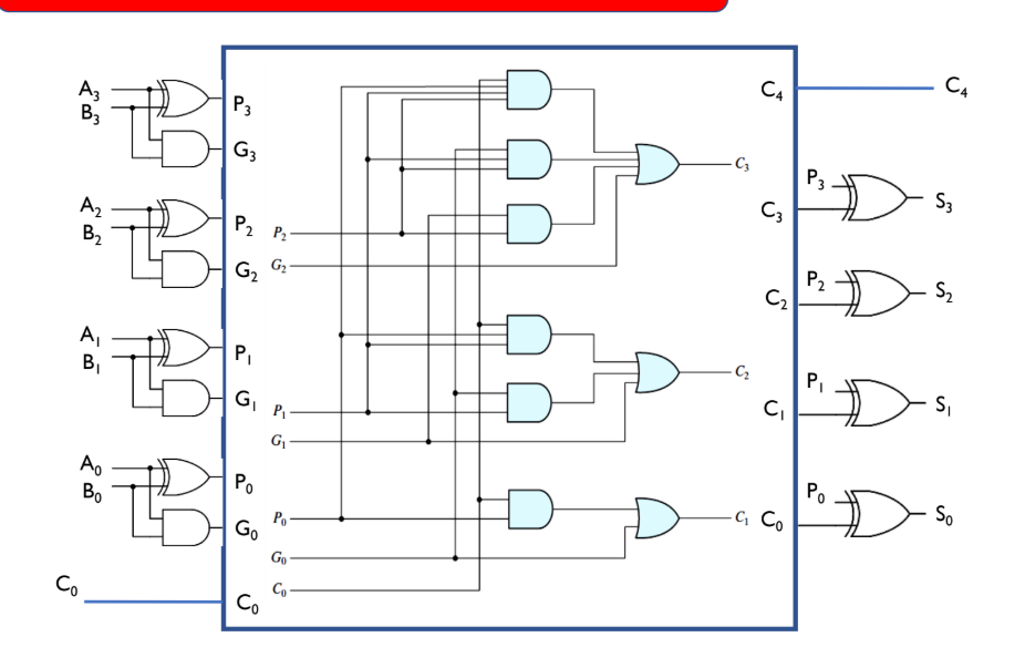
4-Bits Full Adder with Look Ahead Generator Ckt:
BCD Adder (Binary Coded Decimal Adder)
A _________ is a digitalcircuit that adds two decimal numbers represented in BCD (Binary-Coded Decimal) form.
Magnitude Comparator
A _________ is a combinational logic circuit that compares two binary numbers (A and B) and determines their relative magnitude,
BCD-to-Decimal Decoder
A _________ is a combinational logic circuit that converts a 4-bit BCD (Binary-Coded Decimal) input into one of ten active outputs, corresponding to the decimal digits 0 through 9.
Decoder
A _____ is a combinational logic circuit that converts binary inputs into a unique, active output line.
An n-bit binary input into 2n possible outputs, with only one output active (HIGH or LOW) at a time.
Decimal-to-BCD Decoder
A _________ (more precisely, a BCD-to-Decimal Decoder) is a combinational logic circuit that converts a BCD input into its corresponding decimal output.
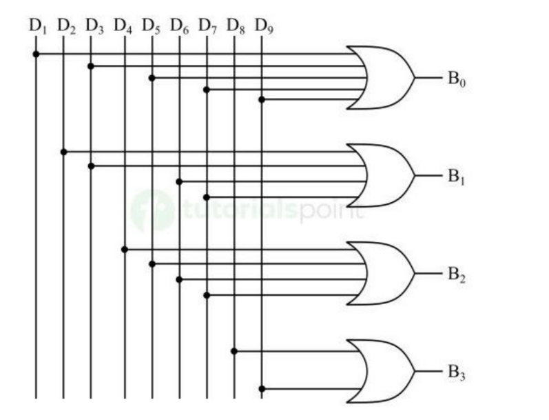
Decimal-to-BCD Decoder Ckt:
Combinational Logic Implementation
Any Boolean function can be expressed in sum of minterms.
Use a decoder to generate the minterms and an external OR gate to form the sum.
Encoder
An _____ is a combinational logic circuit that converts active input signals into a coded binary output.
• 4 to 2 Encoder
• 8 to 3 Encoder (Octal Encoder)
• Decimal to BCD Encoder
Types of Encoders:
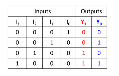
4 to 2 Encoder
It is a type of encoder which has 4 (2²) input lines and 2 output lines. It produces an output code (i.e., convert input information in a 2-bit format) depending on the combination of input lines.
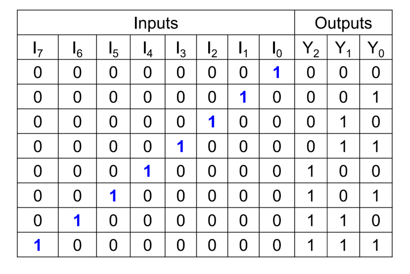
Octal to binary encoder
The _________ is a type of encoder that converts an octal code into binary code. It accepts 8 input lines and produces a 3-bit output depending on the combination of input lines.
8 to 3 Encoder.
Octal to Binary Encoder also known as?
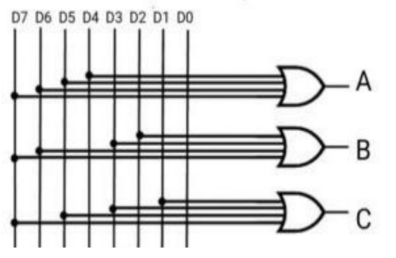
8 to 3 Encoder Ckt: