Transformers
1/17
There's no tags or description
Looks like no tags are added yet.
Name | Mastery | Learn | Test | Matching | Spaced | Call with Kai |
|---|
No analytics yet
Send a link to your students to track their progress
18 Terms
Transformer
a device that transfers electric energy from one alternating current circuit to one or more other circuits, either increasing or decreasing the voltage through the process of electromagnetic induction
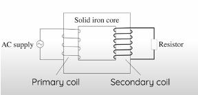
Structure
A primary coil – the coil that is connected to the AC power supply
A secondary coil – the coil that is experiencing the change in flux
A transformer core, generally made from soft iron connecting the two coils
Ferromagnetic = it amplifies the magnetic field of the primary coil
Has increased magnetic permeability compared to air = magnetic field lines prefer to flow through the core, allowing it to be directed towards the secondary coil.
How transformers work
The primary coil is connected to an AC power supply
AC power supply changes the direction of current and its magnitude → does NOT work for DC current, since it has the primary solenoid creates a constant current (unless switch opens/closes), thus a constant B field, so there is no change in flux or EMF induced in the secondary
Its graph of current over time generally shows a sinusoidal wave
The current generates a magnetic field in the coil, but its strength changes sinusoidally along with the current
The magnetic flux produced by the primary coil is transmitted through the iron core into the secondary coil
The secondary coil experiences a change in flux and according to Faraday’s law this induces an EMF (electromotive force)
Since the circuit is closed, an induced current flows to create a magnetic field in the direction opposing the change in flux according to Lenz’s law.
The current and the emf of the primary and secondary coils are out of phase. → since EMF is the NEGATIVE DERIVATIVE of flux (current + flux max for primary = min emf and current in secondary)
Purpose
to change the voltage (emf) during transmission of electrical energy
Step up transformer = Increases the voltage in the second coil, decreased current
When Ns < Np → decrease the number of turns in secondary coil
Step down transformer = Decreases the voltage in the second coil, increased current
When Ns > Np → increase the number of turns in secondary coil
Ideal transformers follow the ratios (no power loss, so 100% efficient)
Vp Ip=Vs Is
Vp/Vs = Np/Ns = Is/Ip
Transformers in reality
Power is loss since energy is transformed into other forms:
Power in primary > Power in secondary
Energy lost = Pprimary - Psecondary
Ploss = I²R = Vdrop²/R
Transformer efficiency – the percentage of power transferred from the primary coil to the secondary coil
Efficiency= (Psecondary/Pprimary) ×100
Limitations/power loss caused by
generation of eddy currents in core
incomplete flux linkage
Resistive heat production
hysteresis (not in syllabus)
Incomplete flux linkage
Occurs when not all the magnetic field lines generated by the AC current in the primary coil are transferred to the secondary coil
∴ the full change in flux is not experienced by 2nd coil
∴ not all the electrical energy from the 1st coil is transferred to the 2nd coil
Iron core improves the transmission of magnetic flux, but some is not transmitted → voltage in secondary coil is lower than calculated by Np/Ns= Vp/Vs)
The core naturally contains some magnetic reluctance that opposes the flow of the magnetic flux → contribute to incomplete flux linkage
Generally, the stray field (lines that go outside of the solenoid) are not transmitted
Solutions for Incomplete flux linkage
SOLUTION 1: Decrease the length of the path between the two coils
•Coils are further apart = more flux can be lost or opposed by the core
Achieved by coiling the secondary coils over the primary coils around the same limb and separating the coils using an insulating layer / put one coil inside the other
Reducing the distance decreases magnetic reluctance, improving flux linkage
SOLUTION 2: Change the shape of the core
Toroidal (circular/donut)
Continuous magnetic path = more uniform magnetic field = Highest efficiency due to lower flux leakage
Square
Sharper corners = less uniform magnetic field = Lower efficiency due to higher leakage flux
SOLUTION 3: Decrease air gaps in the core
Air gaps decrease permeability of a transformer and increase the magnetic reluctance, reducing its ability to redirect the magnetic field and increasing the opposition to flux, causing more flux to be lost along the way
Resistive heat production
Occurs when electrical energy is lost as heat by the system due to resistance → IN COILS
Primary and secondary coils have electrical resistance (ohms)
When there is resistance, then electrical energy is converted to heat when current travels through = electrons collide with particles of material, so their kinetic energy is transferred to heat
When heat increases, this further increases resistance, causing a runaway effect →THERMAL RUNAWAY
Solutions for Resistive heat production
SOLUTION: Reduce heat lost due to the resistance, by changing the factors that influence it
→ If R decreases, then Ploss = I²R will decrease as well
Use a different coil material with lower resistivity copper is universally accepted standard for manufacturing wires due to its cheapness, durability, high conductivity
e.g. Silver: BUT very expensive and highly reactive (corrodes easily)
e.g. superconductors - “substance that offers no resistance to the electric current when it becomes colder than a critical temperature”
The critical temperature needs to be constant for it to function as desired, which can be impractical and require expensive materials
e.g Aluminium = 1.2 K = approx -273°C
Increase the cross-sectional area of the wire in the coil
Lower the temperature by… to reduce the runaway effect of heat and resistance
e.g. Implement internal fans and vents in the transformer to ensure adequate ventilation
e.g. Adding heat sink blades to increase surface area to allow for better heat dissipation
e.g. Make a black transformer case, so that the heat produced can be efficiently absorbed and re-radiated to the environment = why most small transformer-rectifier units are black.
e.g. Oil cooling = absorbs heat generated and carries it away (high thermal conductivity)
Generation of eddy currents in the iron core
Eddies are electrical energy created by a change in flux, but dissipate energy in the form of heat
Since the soft iron core is an electrical conductor, it experiences a change in flux due to the AC power supplied to the primary coil
According to faraday’s law, this induces and emf in the core
This produces eddy currents that flow to oppose the change in flux (Lenz’s law)
Eddy currents convert the electrical energy into heat due to high electrical resistance of iron → not ideal since we want to maximise efficiency
Can determine the direction of eddy currents using right-hand grip rule
They circulate in a plane perpendicular to the plane of the primary coil
Result in heat loss of Ploss = I²R
Practical applications of eddy currents
Induction stove
There are electromagnetic coils under the stove connected to AC power source = change in flux = emf in the pan, which is a conductor = eddy currents produced = dissipate into heat = cook food
solutions for eddy currents in the core
SOLUTION: Minimise eddy currents by laminating the iron core
Lamination – separating layers of conductive material with insulating mate rial
Less area for eddy currents to form = less heat dissipated
Needs to be laminated in a specific way to effectively reduce eddies (perpendicular to the plane of the coil)
Vertical lamination: slicing the material in the opposite plane to the eddy currents = less area for eddies to form = makes them smaller
Horizontal lamination: slicing the material in the same plane to the eddy currents = area is not reduced = does not reduce the size of eddy currents
Hysteresis loss (not in syllabus)
Hysteresis - lagging of the magnetization of a ferromagnetic material, behind variations of the magnetizing field.
“loss is caused by the magnetism that remains in a material after the magnetising force has been removed” (Grant Transformers, 2024).
Energy lost as heat when the core is magnetised and demagnetised
Magnetic domains must realign when polarity of field changes = energy is consumed to change the domains of the core lost as heat due to the friction generated
Worsened by how transformers use AC current → domains are frequently realigning
SOLUTION: Make the core out of soft magnetic materials e.g. soft iron instead of hard iron
Consume less energy to realign domains when magnetisation is reversed
Reaches saturation magnetisation (the point where increasing the field doesn’t increase magnetisation of the material) with a relatively low magnetic field (Inoue & Kong, 2022)
They have more narrow magnetic hysteresis windows
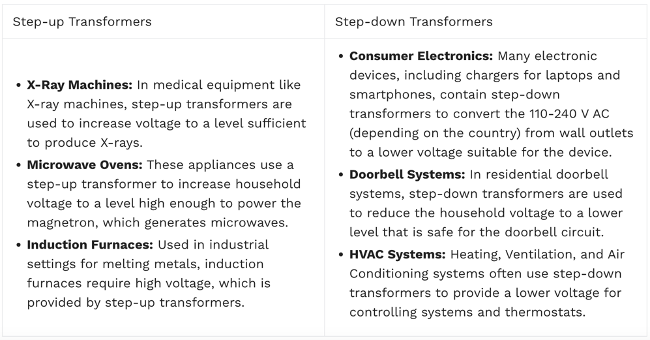
Other Applications of Step-up and Step-down transformers
Power transmission
Power stations produce electricity by burning coal, solar farms, wind farms, nuclear power stations
They need lots of land, can be dangerous, produce pollution, need to be located near fuel (coal, where there is lots of sun/wind) so are located relatively far from metropolitan areas
Thus, Power transmission occurs over long distances
Power loss during transmission
Power is lost during transmission from the station to homes
Due to resistive heat production, dependant on:
Magnitude of current
Resistance of power line
The long distance of power transmission results in a long conductor length: Since resistance, R=ρL/A → The resistance of the wire is very high
The power lost is observed as a voltage drop between the output and input

Use of step-up and step-down transformers in power transmission
We can reduce power loss by reducing the resistance (R)
increasing cross sectional area = expensive over long distances
Use materials that have better conductivity like gold or silver = very expensive
Decreasing the temperature = impractical since lines are exposed to the weather
But that is impractical, so we reduce the current instead, using transformers
Step-up transformers (increase voltage, decrease current) | To decrease the power lost during transmission
Step up transformers reduce power loss during transmission by decreasing the amount of current through the transmission line: Ploss=I²R
|
Step down transformers (decrease voltage, increase current) | To decrease the voltage as the current gets closer to where it will be used
|
Role of Insulators in Transmission wires
Transmission wires are insulated (using ceramic) from the supporting structures (made of metals)
Provide a safe distance between the conductors and supporting structures
Otherwise, current will flow through the structure into the earth (due to grounding)
Present danger of electrocution, and make transmission less efficient (due to loss of electrical energy)
Why do transformers need to be cooled
due to heat generated
Transformers get hot due to heat dissipated by eddy currents and copper losses due to the resistance in wires (+ hysteresis)
Too much heat can cause issues:
Insulation of coils could melt
Transformer could short circuit
Transformer could be destroyed/have its lifespan reduced → damages components
Poses a fire hazard
Further reduces efficiency