Airport Lighting and Other Visual Aids
1/44
There's no tags or description
Looks like no tags are added yet.
Name | Mastery | Learn | Test | Matching | Spaced | Call with Kai |
|---|
No analytics yet
Send a link to your students to track their progress
45 Terms
Approach Light System (ALS)
helps pilots transition from instrument to visual flight. They extend from the runway threshold into the approach area (longer for precision runways) and may include sequenced flashing lights.
Visual Glide Slope Indicators
Visual glide slope indicators provide visual descent guidance during approach once the aircraft is aligned with the runway.
VASI (Visual Approach Slope Indicator)
uses red and white lights arranged in bars to show if the aircraft is on, above, or below the glide path (usually 3°).
VASI indications
•White over white: too high
•White over red: on glide path (≈3°)
•Red over red: too low
Vasi Visibility
3-5 miles day, up to 20+ miles night
PAPI (Precision Approach Path Indicator)
Uses 2 or 4 lights in a single row with red/white indications.
PAPI indications
•4 white: too high
•3 white / 1 red: slightly high
•2 white / 2 red: on glide path
•1 white / 3 red: slightly low
•4 red: too low
PAPI visibility
~5 miles day, up to 20 miles night
Tri-Color Visual Approach Slope Indicator
•Green: on glide path
•Amber: above glide path
•Red: below glide path
Tri-Color Visual Approach Slope Indicator visibility
½-1 mile day, up to 5 miles night
Pulsating Visual Approach Slope Indicator (PVASI)
Single light using steady or pulsating red/white signals to indicate glide path.
Pulsating Visual Approach Slope Indicator (PVASI) indications
Steady white or alternating red/white: on glide path
Pulsating white: above glide path
Steady red: slightly below glide path
Pulsating red: well below glide path
Pulsating Visual Approach Slope Indicator (PVASI) visibility
~4 miles day, up to 10 miles night
Alignment of Elements System
•Middle element far = above glide path
•Elements lined up = on glide path
•Middle element near = below glide path
Alignment of Elements Visibility
3/4 mile
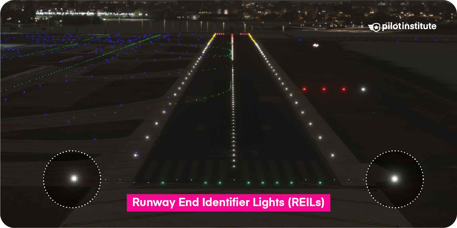
Runway End Identifier Lights (REIL)
A pair of synchronized flashing lights, located laterally on each side of the runway threshold, providing rapid and positive identification of the approach end of a runway.
Runway Edge Light Systems
purpose: used to outline the edges of runways during periods of darkness or restricted visibility conditions
what: white lining lights ... except for instrument runways, where they are yellow; for the last 2,000 ft., where they are red to departing aircraft and green to approaching aircraft
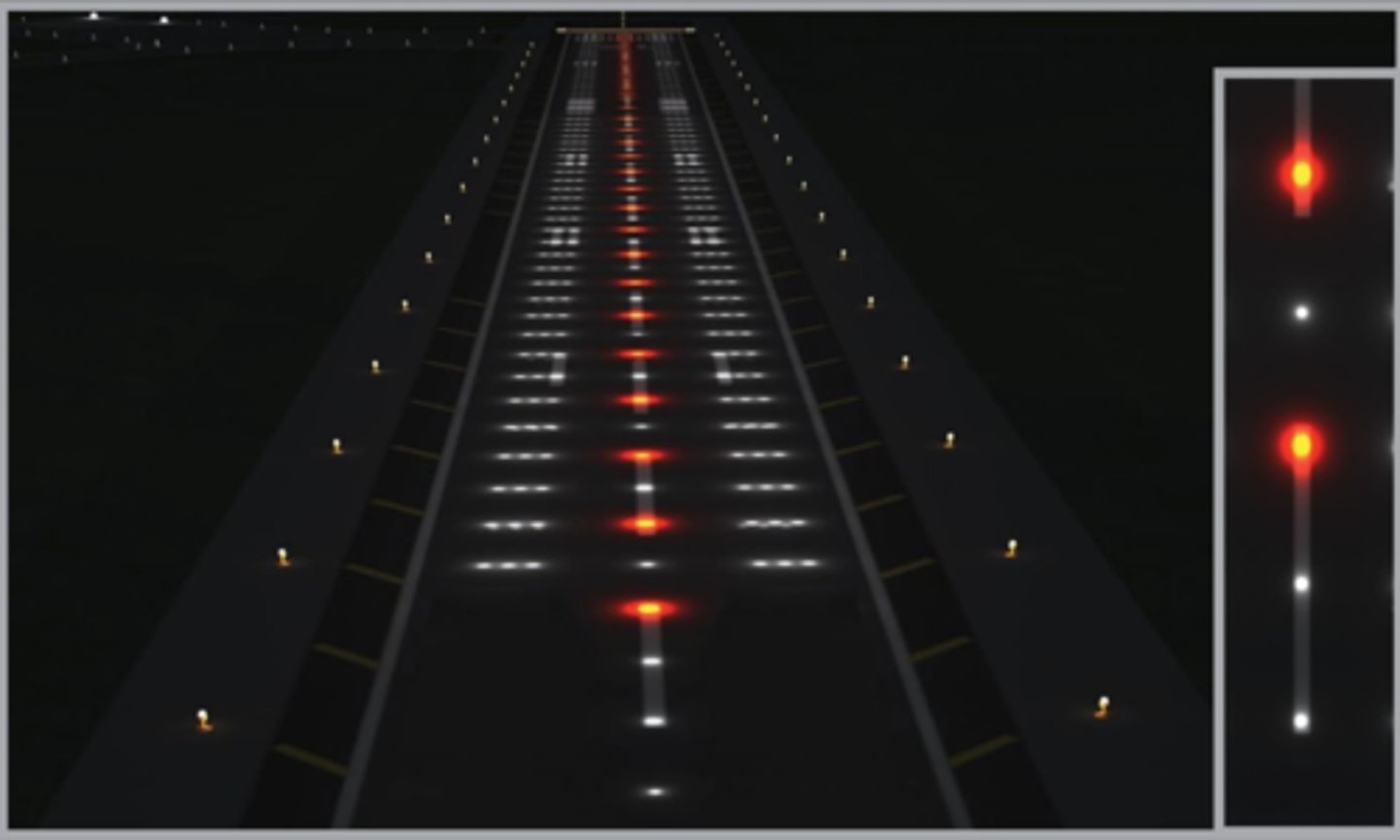
Runway Centerline Lighting System (RCLS)
1. From the threshold ~last 3,000ft- white
2. last 3,000ft ~ last 1,000ft- alternating white and red
3. last 1,000ft- red
4. Lights interval- 50-foot
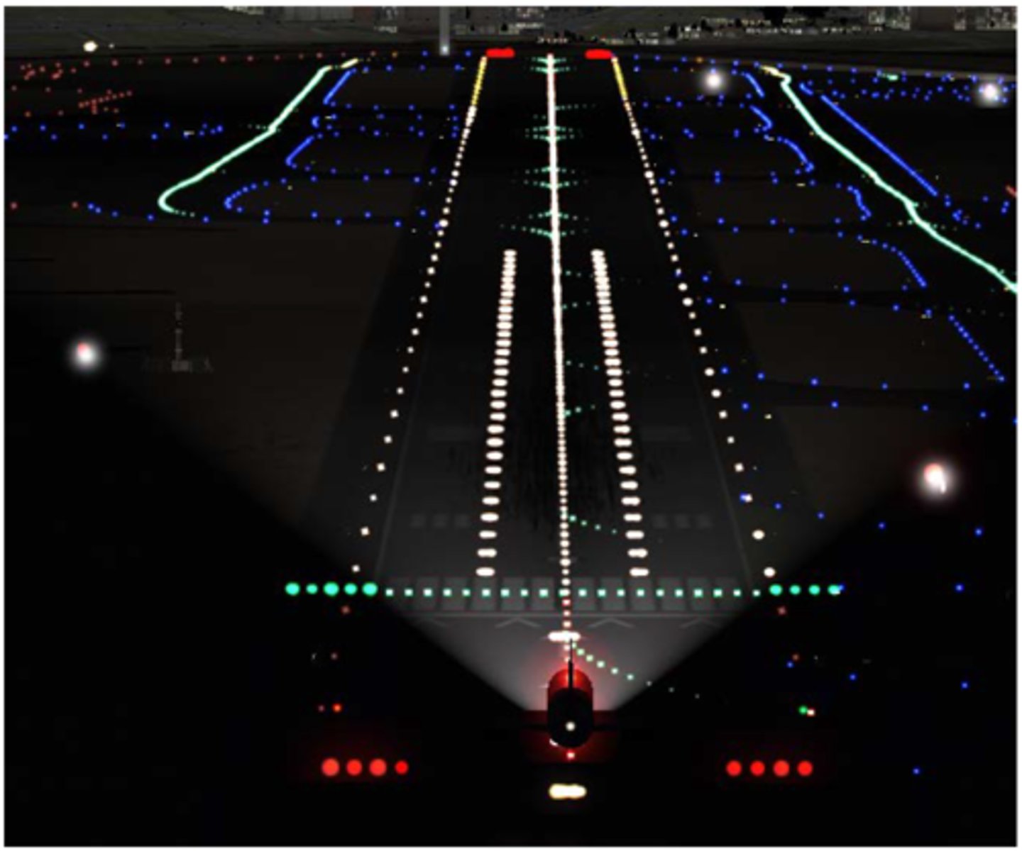
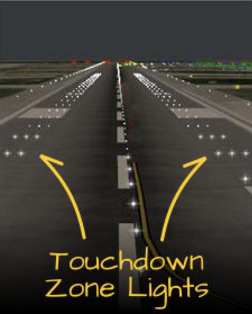
Touchdown Zone Lights (TDZL)
Two rows of transverse light bars disposed symmetrically about the runway centerline in the runway touchdown zone.
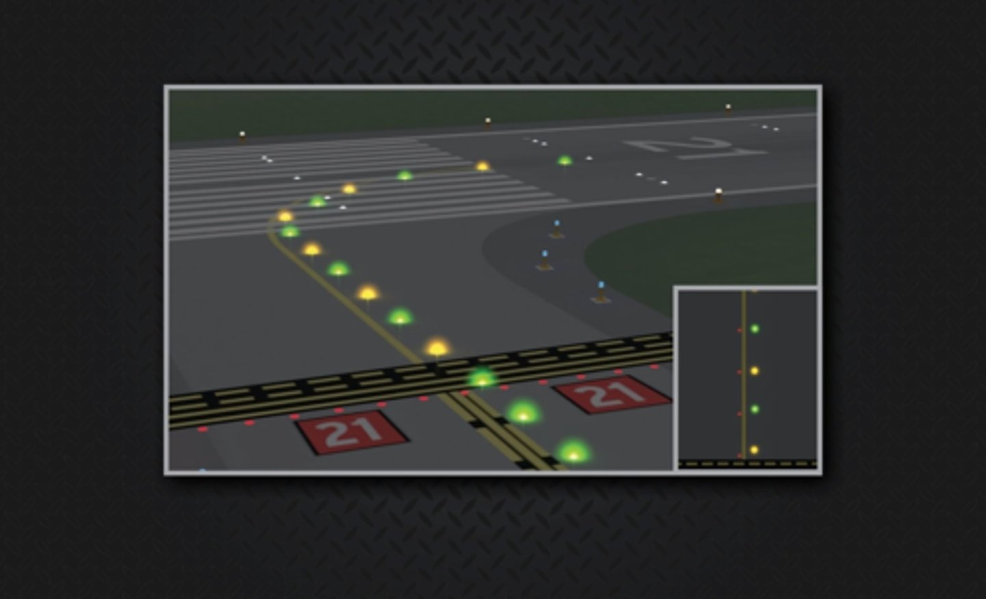
Taxiway Centerline Lead-Off Lights
Installed to provide visual guidance to persons exiting the runway
They are color-coded to warn pilots and vehicle drivers that they are within the runway environment or instrument landing system (ILS) critical area, whichever is more restrictive
Alternate green and yellow lights are installed, beginning with green, from the runway centerline to one centerline light position beyond the runway holding position or ILS critical area holding position
Taxiway Centerline Lead-On Lights
Installed to provide visual guidance to persons entering the runway
They are color-coded to warn pilots and vehicle drivers that they are within the runway environment or instrument landing system (ILS) critical area, whichever is more conservative
The fixtures used for lead-on lights are bidirectional, i.e., one side emits light for the lead-on function while the other side emits light for the lead-off function
Any fixture that emits yellow light for the lead-off function must also emit yellow light for the lead-on function
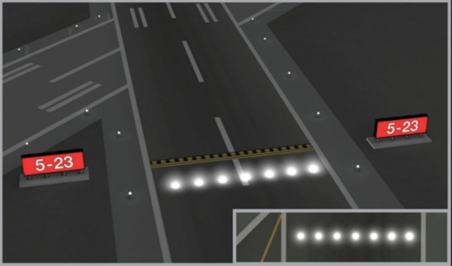
Land and Hold Short Lights
Pulsing white lights installed across the runway at the hold short point
Runway Status Light (RWSL) System
The RWSL is a system of runway and taxiway lighting to provide pilots increased situational awareness by illuminating runway entry lights (REL) when the runway is
unsafe for entry or crossing, and take off hold lights (THL) when the runway is unsafe for departure.
Runway entry lights (REL)
red, in-pavement lights along the taxiway centerline at runway hold lines. When illuminated, they warn pilots that the runway is unsafe to enter or cross due to an aircraft on the runway or on short final.
For departing aircraft, RELs ahead of the aircraft illuminate once it reaches about 30 knots and turn off just before the aircraft reaches each intersection. All lights turn off after liftoff.
For arriving aircraft, RELs illuminate when the aircraft is about 1 mile from the runway and progressively turn off as the aircraft slows and exits the runway.
If a pilot sees red RELs, they must stop and hold short and contact ATC if the lights conflict with a clearance.
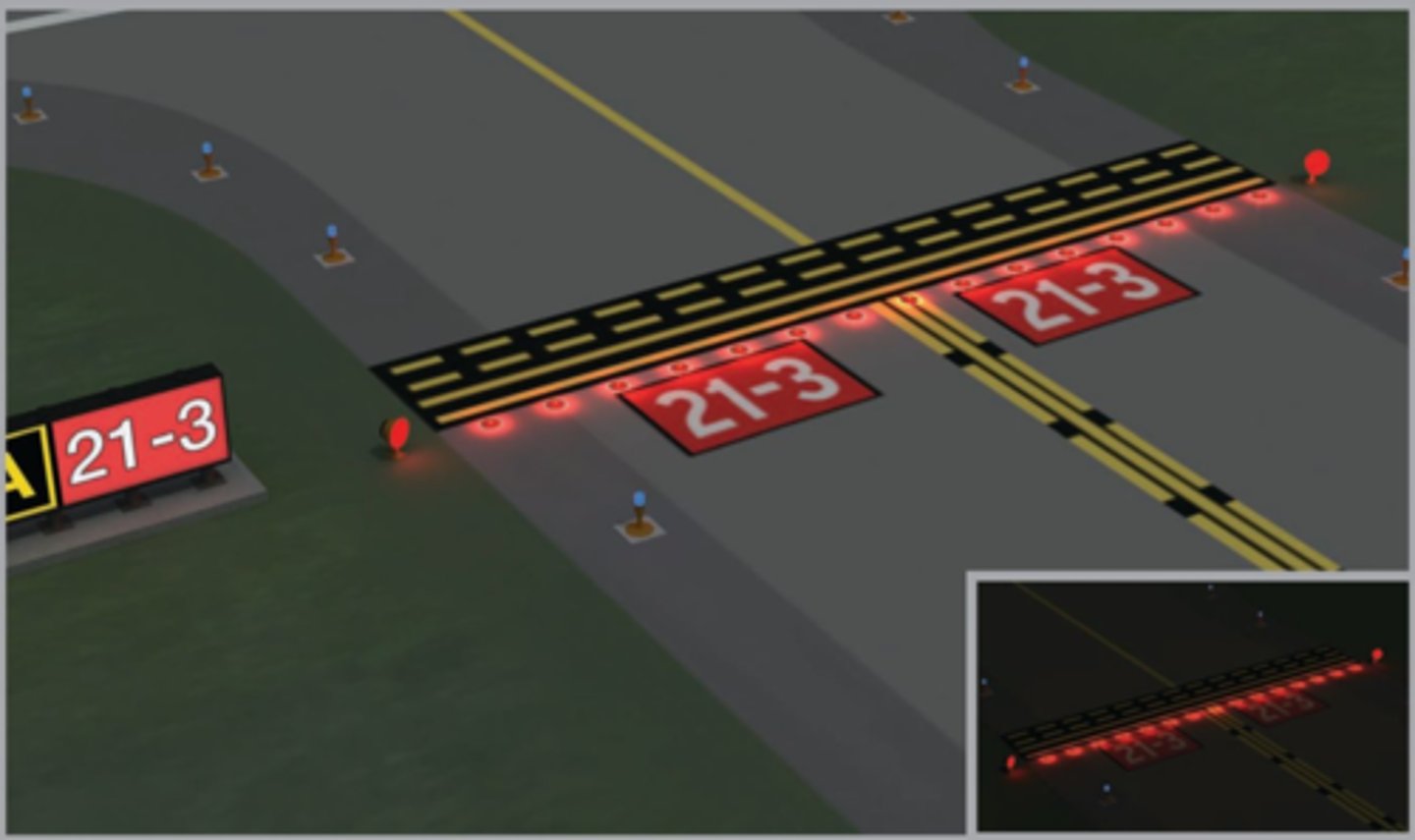
Takeoff Hold Lights (THL)
Takeoff Hold Lights (THL) are red, in-pavement lights arranged in two rows along the runway centerline ahead of an aircraft in position for takeoff. They indicate it is unsafe to take off because another aircraft or vehicle is on or about to enter the runway.
THLs illuminate when an aircraft is lined up or beginning its takeoff roll and there is conflicting runway traffic. The lights extinguish when the runway is clear, but this does not replace an ATC takeoff clearance.
If a pilot sees red THLs, they should stop if able and contact ATC if the lights conflict with a clearance.
Pilot Actions of RWSL
When operating at airports with Runway Status Lights (RWSL), pilots must keep the transponder/ADS-B on from leaving the gate until shutdown to ensure proper system operation.
Pilots must never cross illuminated red lights and must stop and contact ATC if RWSL indications conflict with a clearance.
RWSL does not replace ATC clearance—do not proceed just because the lights turn off; always wait for ATC authorization.
ATC Control of RWSL System:
1. Controllers can set in-pavement lights to one of five (5) brightness levels to assure maximum conspicuity under all visibility and lighting conditions. REL and THL subsystems may be independently set.
2. System lights can be disabled should RWSL operations impact the efficient movement of air traffic or contribute, in the opinion of the assigned ATC Manager, to unsafe operations. REL and THL light fixtures may be disabled separately. Whenever the system or a component is disabled, a NOTAM must be issued, and the Automatic Terminal Information System (ATIS) must be updated.
Control of Lighting Systems
1. Operation of approach light systems and runway lighting is controlled by the control tower (ATCT). At some locations the FSS may control the lights where there is no control tower in operation.
2. Pilots may request that lights be turned on or off. Runway edge lights, in-pavement lights and approach lights also have intensity controls which may be varied to meet the pilots request. Sequenced flashing lights (SFL) may be turned on and off. Some sequenced flashing light systems also have intensity control.
Pilot Control of Airport Lighting
At some airports, pilots can control runway and approach lighting by keying the microphone on a published radio frequency, typically when no control tower or FSS is operating. All pilot-controlled lights at an airport use the same frequency.
Microphone Clicks:
7 clicks: highest intensity
5 clicks: medium or lower intensity (or REIL off)
3 clicks: lowest intensity
Lights remain on for 15 minutes after activation.
On runways with approach lights and runway lights, the approach lighting system takes priority for radio control. Some systems (VASI, REIL, taxiway lights) may be controlled independently.
Lighting type, runway, and activation frequency are listed in the Chart Supplement and on approach charts when applicable.
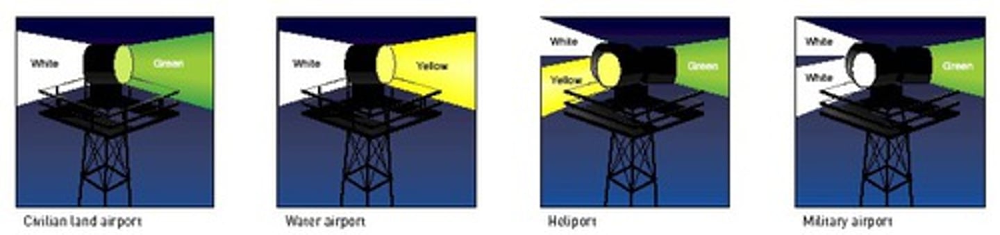
Airport/Heliport Beacons
•White & Green: Civilian land airport.
•White & Yellow: Civil water airport.
•White, Yellow, & Green: Heliport.
•Two White Flashes & One Green: Military airport.
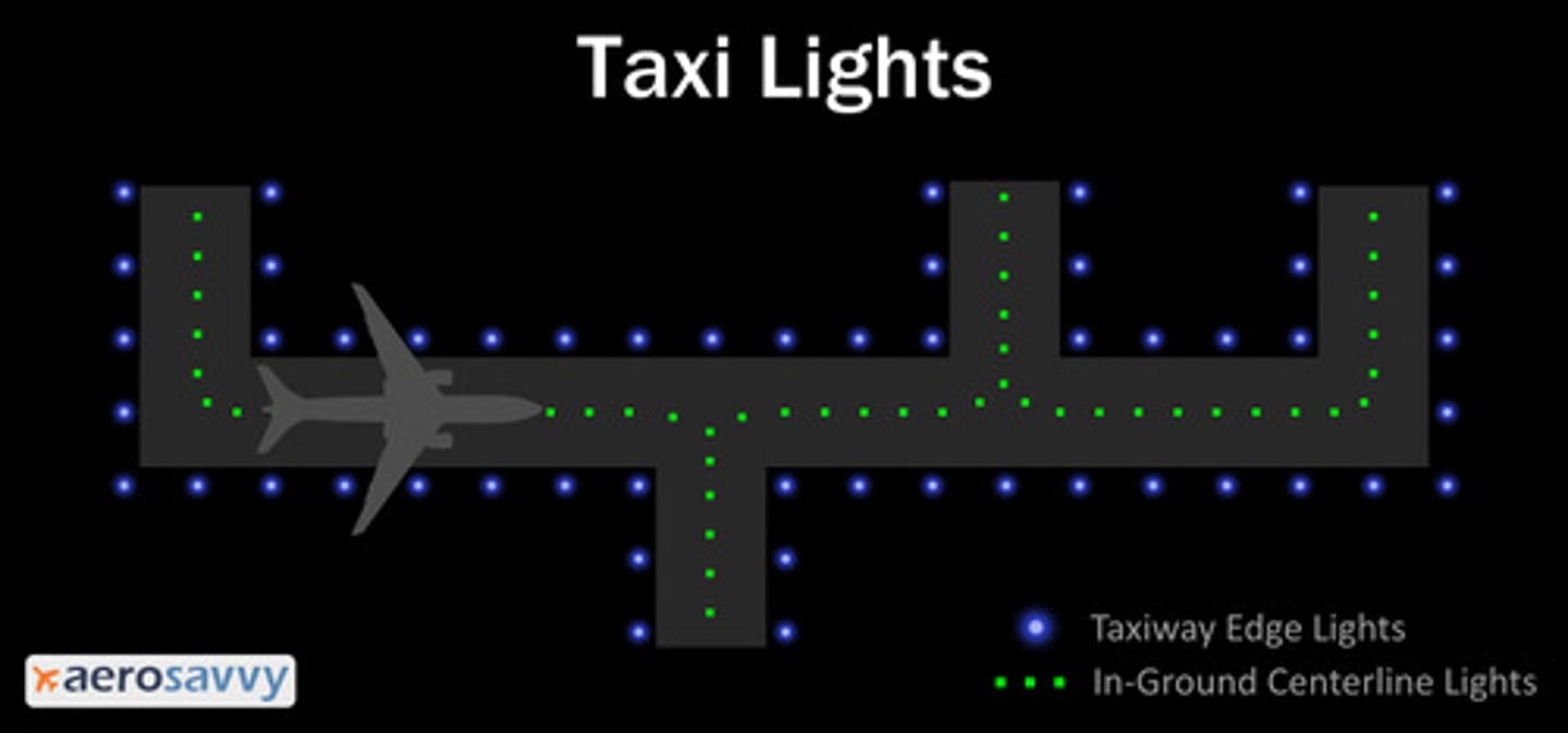
Taxiway Edge Lights
blue lights denoting the edge of a taxiway
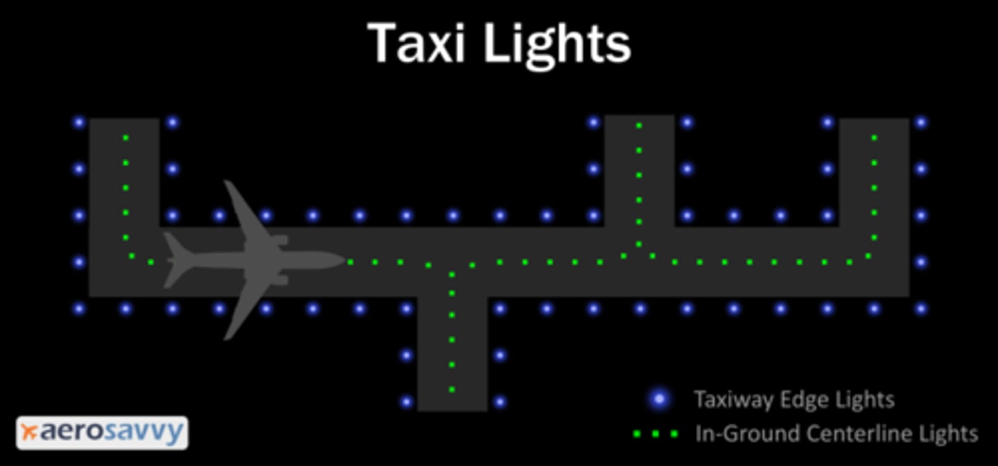
Taxiway Centerline Lights
green lights indicating the middle of a taxiway
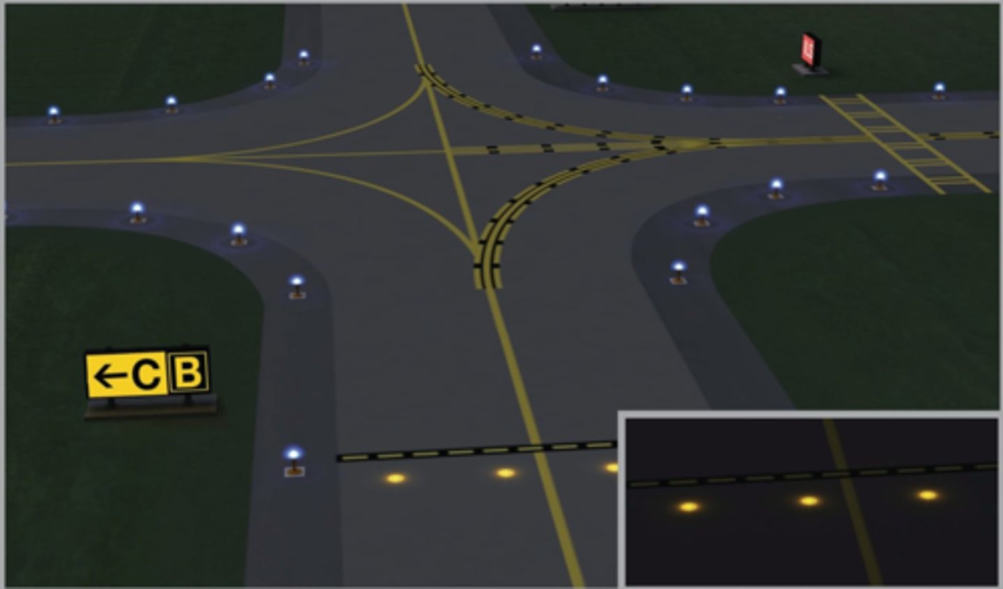
Clearance Bar Lights
purpose: holding positions on taxiways
what: three solid yellow lights
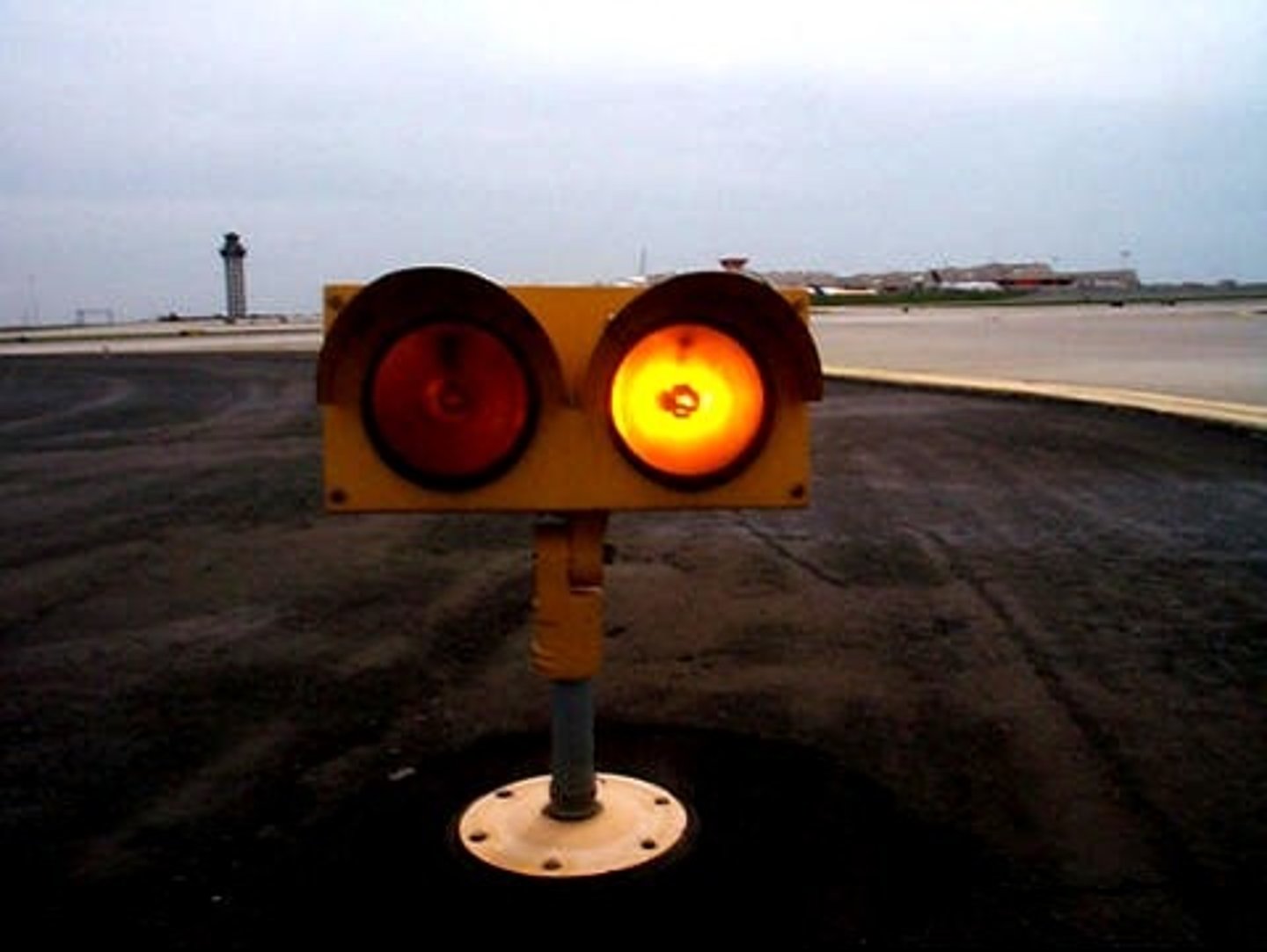
Runway Guard Lights
Intended to alert the pilot of a runway/taxiway intersection
Either two yellow flashing or a row of yellow in ground at hold position
Stop Bar Lights
Stop Bar Lights are red in-pavement lights across the taxiway at the runway holding position, used in low visibility (RVR below 1,200 ft).
Pilots must never cross an illuminated stop bar. After ATC issues clearance, the red stop bar turns off and green taxiway lead-on lights turn on to guide the aircraft onto the runway.
Obstruction Lights
Obstructions are marked/lighted to warn airmen of their presence during daytime and nighttime conditions. They may be marked/lighted in any of the following combinations:
Aviation Red Obstruction Lights
Flashing aviation red beacons (20 to 40 flashes per minute) and steady burning aviation red lights during nighttime operation. Aviation orange and white paint is used for daytime marking.
Medium Intensity Flashing White Obstruction Lights.
Medium intensity flashing white obstruction lights may be used during daytime and twilight with automatically selected reduced intensity for nighttime operation. When this system is used on structures 500 feet (153m) AGL or less in height, other methods of marking and lighting the structure may be omitted. Aviation orange and white paint is always required for daytime marking on structures exceeding 500 feet (153m) AGL. This system is not normally installed on structures less than 200 feet (61m) AGL.
High Intensity White Obstruction Lights
Flashing high intensity white lights during daytime with reduced intensity for twilight and nighttime operation. When this type system is used, the marking of structures with red obstruction lights and aviation orange and white paint may be omitted.
Dual Lighting
A combination of flashing aviation red beacons and steady burning aviation red lights for nighttime operation and flashing high intensity white lights for daytime operation. Aviation orange and white paint may be omitted.
Catenary Lighting
Lighted markers are available for increased night conspicuity of high-voltage (69KV or higher) transmission line catenary wires. Lighted markers provide conspicuity both day and night.
Medium intensity omnidirectional flashing white lighting system
provides conspicuity both day and night on catenary support structures. The unique sequential/simultaneous flashing light system alerts pilots of the associated catenary wires.
High intensity flashing white lights
used to identify some supporting structures of overhead transmission lines located across rivers, chasms, gorges, etc. These lights flash in a middle, top, lower light sequence at approximately 60 flashes per minute. The top light is normally installed near the top of the supporting structure, while the lower light indicates the approximate lower portion of the wire span. The lights are beamed towards the companion structure and identify the area of the wire span.
Also employed to identify tall structures, such as chimneys and towers, as obstructions to air navigation. The lights provide a 360 degree coverage about the structure at 40 flashes per minute and consist of from one to seven levels of lights depending upon the height of the structure. Where more than one level is used the vertical banks flash simultaneously.
LED Lighting Systems
Certain light-emitting diode (LED) lighting systems fall outside the combined visible and near-infrared spectrum of night vision goggles (NVGs) and thus will not be visible to a flight crew using NVGs.
The FAA changed specifications for LED-based red obstruction lights to make them visible to pilots using certain NVG systems, however, other colors may not be visible.
It is recommended that air carriers/operators—including part 91 operators—who use NVGs incorporate procedures into manuals and/or standard operating procedures (SOPs) requiring periodic, unaided scanning when operating at low altitudes and when performing a reconnaissance of landing areas.
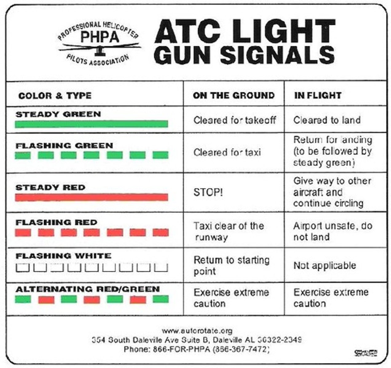
Light Gun Signals
Steady Green
Ground: Cleared for takeoff
Air: Cleared to land
Flashing Green
Ground: Cleared for taxi
Air: Return for landing
Steady Red
Ground: STOP
Air: Give way and continue circling
Flashing Red
Ground: Taxi clear of runway in use
Air: Airport unsafe, do not land
Flashing White
Return to starting point on airport
----
Alternating Red and Green
Exercise extreme caution