Pulse Sequence Design WEEK 5
1/77
There's no tags or description
Looks like no tags are added yet.
Name | Mastery | Learn | Test | Matching | Spaced | Call with Kai |
|---|
No analytics yet
Send a link to your students to track their progress
78 Terms
Pulse sequence-
The process of acquiring patient data by disorienting net magnetization of protons with RF pulses, gradient variations and data collection
What are examples of traditional standard pulse sequences? (4)
Spin echo (SE)
Inversion recovery (IR)
Gradient echo (GE)
Echo planar imaging (EPI)
Pulse sequence timing diagram-
Visualized detailed timing and duration of RF pulses and gradient variations
Echo time (TE)-
The time it takes to complete an entire pulse sequence
What events are recorded by the pulse sequence timing diagram? (5)
RF trasmission (RF-t)
RF receive (RF-r)
Slice select
Readout
Phase
What is important to remember about each event recorded by the diagram?
Each event can initiate or pause another event
What is the first event of the timing diagram?
Radio frequency transmitter (RF-t)
RF-t-
Also known as applied RF pulse, refers to the events that excite or flip net magnetization into the transverse direction
How do RF-t timing events normally begin?
With a 90° initial pulse followed by a 180° pulse
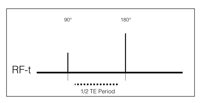
What is this digram?
RF-t diagram

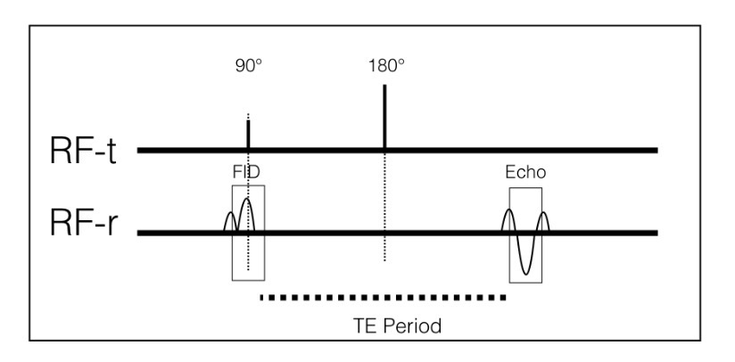
What is the second event of the timing diagram?
Radio frequency receive (RF-r)
When does the RF-r occur?
Begins simultaneously during the 90° and 180° pulses (also known as the dephasing step)
Dephasing-
The progressive weakening of the net magnetization, also known as Free Induction Decay (FID)
Why is RF-r known as the dephasing event?
Because once the net magnetization is disoriented by the 90° pulse, the signal immediately begins to weaken
What unit is echo time (TE) measured in?
Milliseconds (ms)

What is this diagram?
RF-r diagram
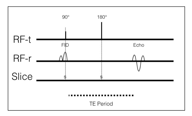
What is the third event of the timing diagram?
Slice select gradient
When does slice select gradient turn on?
During RF transmission
Slice select gradient-
Allows a certain slice to be singled out (spatial localization); allowing for an image of a specific slice to be attained

What is this diagram?
Slice select gradient diagram
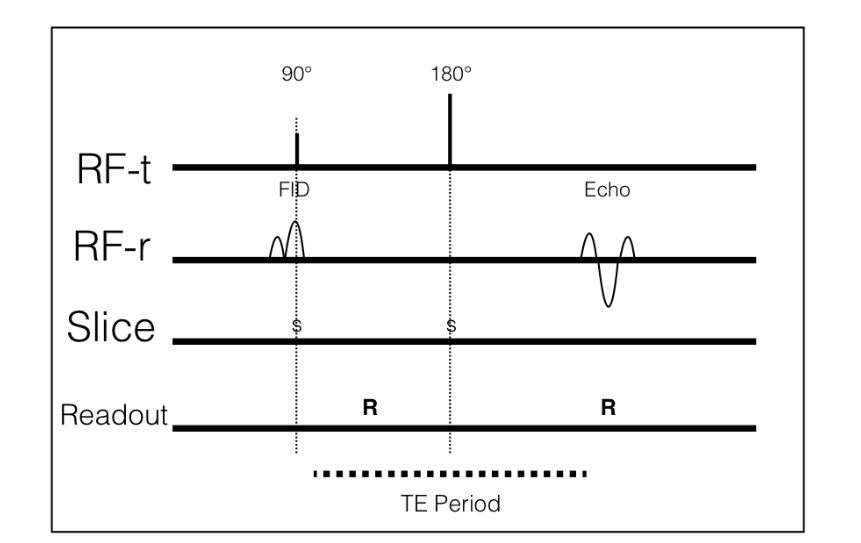
What is the fourth event of the timing diagram?
Readout gradient
Readout gradient-
Reads/samples the signal through a process called frequency encoding
When is readout (or frequency) gradient turned on?
During the frequency encoding; during the resultant echo

What is this diagram?
Readout gradient diagram
What is the fifth event of the timing diagram?
Phase gradient
When is the phase gradient turned on?
Between the 90° and 180° pulses
What is the phase gradient solely determined by?
The number of phase encoding lines in a slice
Ex: 256 (frequency) x 192 (phase) = 192 phase encodes
What is this diagram?
Phase gradient diagram?

What are the types of pulse sequences? (4)
Spin echo
Inversion recovery
Gradient recall echo
Echo planar imaging
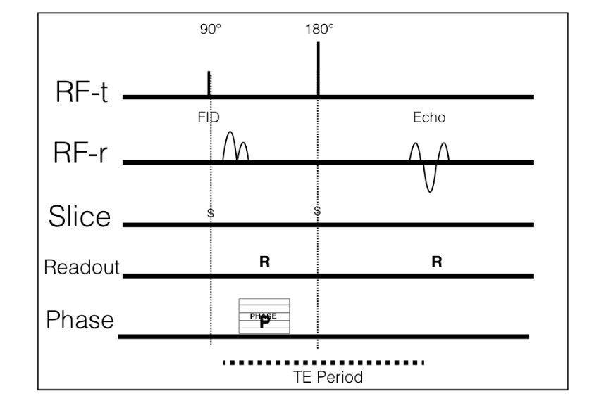
Conventional spin echo sequences (CSE)-
The traditional and basic way to acquire MRI images
What can CSE be?
Either T1, T2, or proton density (PD) weighted
What does CSE contain?
One echo per TE period
True or false? CSE’s have been invoked and rarely used
True; due to scan time length already being long
What is this diagram?
CSE timing diagram

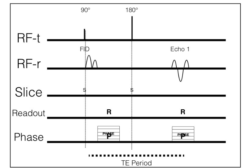
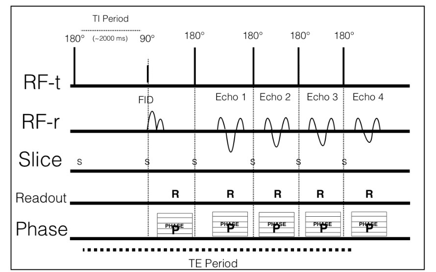
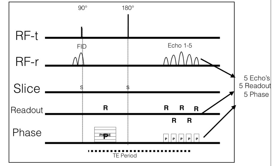
Fast spin echo (FSE) or Turbo spin echo (TSE)-
An innovated and faster sequence compared to CSE
How do FSE’s acquire patient data?
Faster than CSE due to the added echo train length (ETL)
True or false? FSE’s can either be T1, T2, or PD weighted
True
How are FSE’s ETL chosen?
Manually by the technologist during pulse sequence manipulation
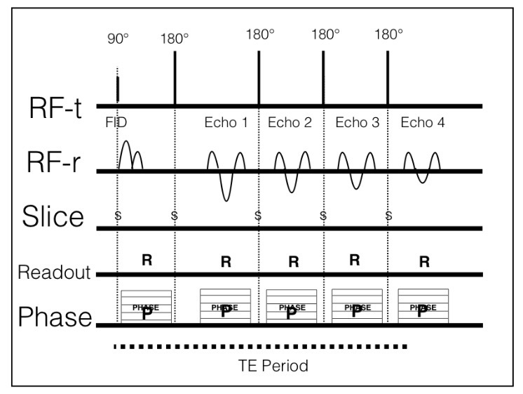
What is this diagram?
FSE timing diagram

Inversion recovery (IR)-
A pulse sequence that contains an additional 180° pulse before the 90° pulse
Inversion time (TI)-
The time from the initial 180° pulse to the 90° pulse
What are the two types of IR pulse sequences?
STIR (Short Tau Inversion Recovery)
FLAIR (FLuid Attenuated Inversion Recovery)
What is the concept of IR?
To establish a T1 environment (relaxation) before the start of a pulse sequence
How to create T1 relaxation?
By flipping the net magnetization with a 180° pulse
What does the 180° pulse cause in regard to IR?
Short T1 tissues to relax quick
Long T1 tissues to relax slow
STIR-
A type of imaging widely used as a fat suppression technique
How do contrast agents work in regard to STIR?
They do not work due to similar short T1 tissue property of fat and gadolinium
How does STIR suppress fat?
By applying a 90° pulse as short T1 tissue (fat) returns to net magnetization. By doing this, Long T1 tissue such as fluid and edema subtracts fat tissue
How will anatomy present with STIR?
All anatomy with high fat content will be saturated black (bone, bone marrow, tendon, and muscle) and will result in anatomy with high water content to be bright (blood, edema, infection)
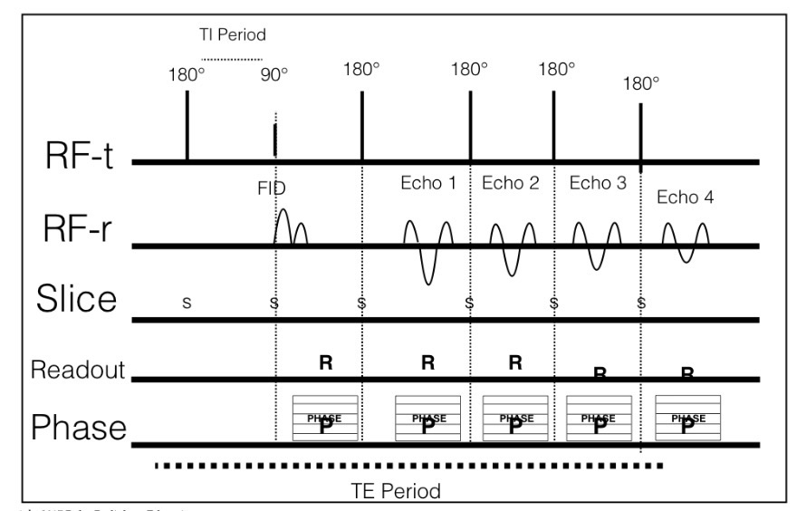
What is this diagram?
STIR timing diagram

FLAIR-
A widely used technique to suppress CSF and highlight diseased periventiruclar tissue such as infarction (stroke), brain/cord lesions (multiple sclerosis), subdural hemorrhage and meningitis
How will anatomy be presented with FLAIR?
All CSF content will be saturated black or “nulled” which will result in the enhancement of diseased tissue (stroke, MS, etc.)
How are FLAIR and STIR similar but different? (2)
Long TI time (about 2000 ms)
Long TR time (about 8000-9000 ms)

What is this diagram?
FLAIR timing diagram
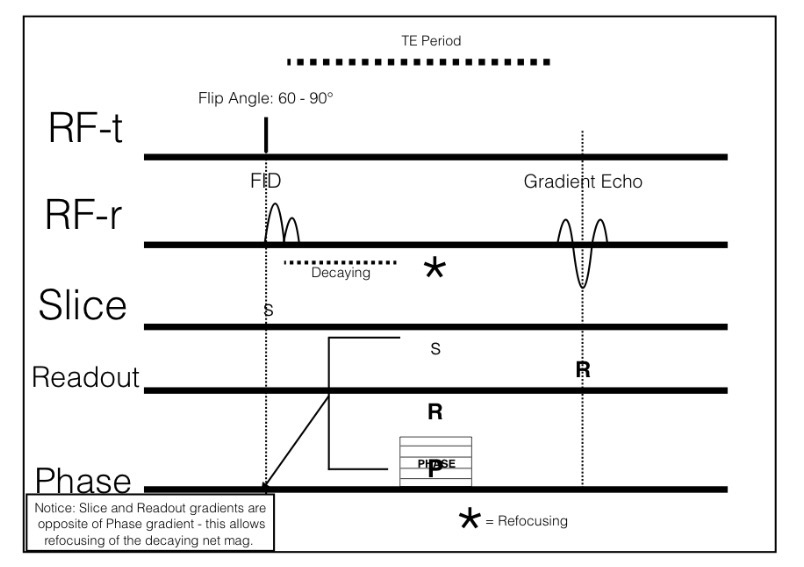
Conventional gradient echo (GE)-
GRE can be used to show blood in brain studies and also serves as a way to show ligaments and cartilage
How does GRE imaging differ from FSE’s and IR’s? (3)
RF flip angles are applied first, NOT initial 90° pulses
Gradient pulses are used to refocus decay, NOT 180° pulses
Slice and readout gradients are used to balance the phase gradient

What is this diagram?
GRE timing diagram
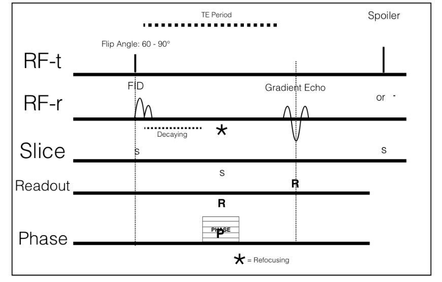
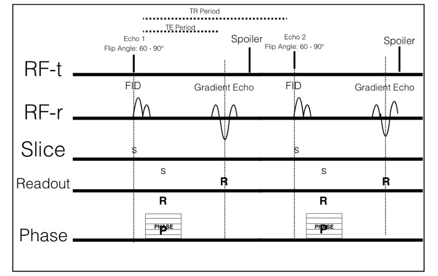
How do spoiled gradient echo’s differ from GRE?
Due to the addition of a spoiler pulse after the readout of a gradient echo
What can the spoiler pulse be?
Either a strong RF pulse or strong gradient pulse
What is reason for the spoiler pulse?
To cancel or terminate any remaining magnetization still in the transverse plane

What is this diagram?
Spoiled GE timing diagram
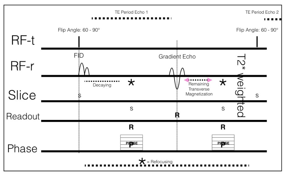
How do steady gradient echo’s differ from spoiled gradient echo’s?
Steady state gradients want to preserve remaining transverse magnetization
How do steady state gradient echo’s preserve remaining transverse magnetization?
By rephrasing
What does rephrasing allow in regard to steady state gradient echo’s?
Both relaxed and remaining net magnetization to both be present for the next initial RF flip angle
What images are the result due to the mix or relaxed and remaining net magnetization?
T2* weighted images

What is this diagram?
Steady state GE timing diagram
What do you need for a GRE to be fast?( 3)
Short TR
Short TE
Smaller flip angle
How do fast gradient echo’s (GRE) gain contrast properties?
By establishing the contrast before the initial flip angle by applying RF pulses
What type of pulse is used for T1 weighting fast GRE?
180° pulse is used
What type of pulse is used for T2 weighting fast GRE?
90°, 180°, 90° pulse combination is used
What is used to accelerate the relaxation process at the end of fast GRE’s?
A spoiler is used

What is this diagram?
Fast GRE timing sequence
Echo planar imaging (EPI)-
The fastest and loudest MRI technique
What does EPI require? (2)
Larger amounts of gradient echo in one TR cycle by:
Alternating readout (frequency encoding) gradients
Collecting phase at each alternation
What is this diagram?
EPI timing diagram

Magnet (MRI)-
The magnetic field is the environment needed to align hydrogen protons along the magnetic field direction
Resonance (MRI)-
Radiofrequency pulses excite the static protons resulting in resonance and an emission of signal
Imaging (MRI)-
Copper coils are positioned around the anatomy of interest. These coils capture the emitted signal and transfers the data collected into 3-dimensional images