Topic 10 - electricity and circuits
1/45
There's no tags or description
Looks like no tags are added yet.
Name | Mastery | Learn | Test | Matching | Spaced |
|---|
No study sessions yet.
46 Terms
the structure of the atom
positively charged nucleus surrounded by negatively charged electrons
subatomic particle | relative mass | relative charge |
proton | 1 | +1 |
neutron | 1 | 0 |
electron | 0 (0.0005) | -1 |
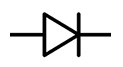
symbol drawing for diode
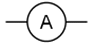
symbol drawing for ammeter
symbol drawing for LDR

symbol drawing for thermistor

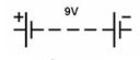
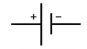
symbol drawing for battery
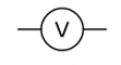
symbol drawing for voltmeter
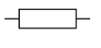
symbol drawing for fixed resistor
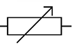
symbol drawing for variable resistor
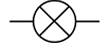
symbol drawing for filament bulb
symbol drawing for cell
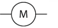
symbol drawing for motor
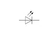
symbol drawing for LED
series circuit
closed circuit
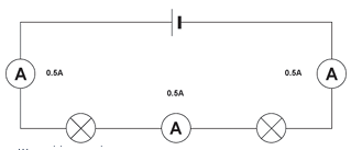
the current is the same everywhere
parallel circuits
branched circuit
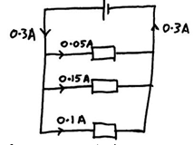
current splits into multiple paths
total current into a junction = total current in each of the branches
voltage is the same across each “branch”
potential difference (represented as ‘V’)
potential difference is measured in Volts
energy transferred per unit charge, Joule per Coulomb
measured across two points, as it is the amount of energy per unit charge to move from one point to the next
measured with a voltmeter, placed in parallel across a component
there can be a voltage across a component, in a closed or open circuit
when it is in a closed circuit, and there is a potential difference (voltage), current will always flow
E = QV
energy transferred (joule, J) = charge moved (coulomb, C) x potential difference (volt, V)
where is a voltmeter connected
a voltmeter is connected in parallel with a component to measure the potential difference (voltage), in volt across it
where is an ammeter connected
an ammeter is connected in series with a component to measure the current, in amp, in the component
current (represented by ‘I’)
current is measured in amps
it is the rate of flow of charge (the flow of electrons in the wires)
measured by any single point on the circuit
measured with ammeter which is placed in series
V = IR
potential difference (volt, V) = current (ampere, A) x resistance (ohm, Ω)
when a closed circuit includes a source of potential difference there will be a current in the circuit
current is conserved at a junction in a circuit
equation for charge
charge (coulomb, C) = current (ampere, A) x time (second, s)
Q = I x t
resistance
greater resistance, the harder it is for change to flow through the component, therefore the current is smaller
variable resistor changes the amount of resistance of the component, changing the amount of current that flows in the circuit
if two resistors are in series, the net resistance is increased, whereas with two in parallel the net resistance is decreased
series
components are connected end to end
all the current flows through all the components
can only switch them all off at once
PD (potential difference) is shared across the whole circuit
PD of power supply = sum of PD across each component
current is the same through all parts of the circuit
current at one point = current at any other point
total resistance is the sum of the resistance in each component R1 + R2 = R
resistance of two components is bigger than just one of them, because the charge has to push through both of them when flowing round the circuit
parallel
components are connected separately to the power supply
current flows through each one separately
you can switch each component off individually
PD is the same across all branches
PD of power supply = PD of each branch
because charge can only pass through any one branch
current is shared between each of the branches
current through source = sum of current through each branch
total reistance is less than the branch with the smallest resistance
two resistors in parallel will have a smaller overall resistance than just one - 1/R1 + 1/R2 = 1/R
because charge has more than one branch to take, so only some charge will flow along each branch
how resistance changes: with current
as current increases, electrons (charge) has more energy
when electrons flow through a resistor, they collide with the ions in the resistor
the current here is doing work against the resistance
this transfers energy to the ions, causing them to vibrate more (heating resistor)
this makes it more difficult for electrons to flow through the resistor
so resistance increases, and current decreases
this may be a benefit, as some appliances like a toaster use heating filaments that have a high resistance to get hot easily
how resistance changes: with temperature
normal wires - see above, the same process occurs as atoms vibrate when hot
THERMISTER ONLY
hotter temperatures, resistance is lower
used in temperature detectors/thermostats
how resistance changes: with length
greater length, the more resistance, and the lower the current
electrons make their way through more resistor atoms, so it is harder to get through than if you were using a shorter wire
how resistance changes: with cross sectional area
thinner wires give greater resistance
because less overall room for electrons to pass through between atoms
how resistance changes: with light
LDR (light dependent resistor) ONLY
greater the intensity of light, the lower the resistance
so resistance greatest when dark
used in automatic night lights
how resistance changes: with voltage
DIODIE ONLY
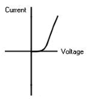
diode allows current to flow freely in one direction
in the opposite direction, it has a very high resistance, so no current can flow
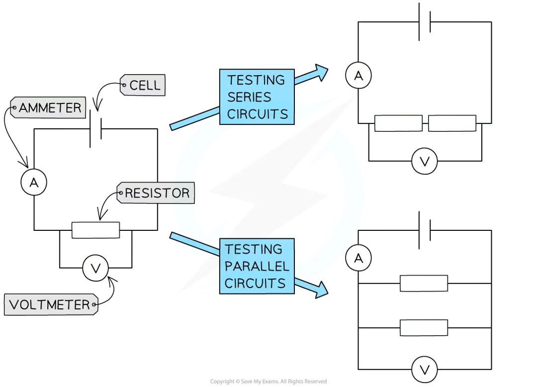
Core practical: construct electrical circuits to:
a) investigate the relationship between potential difference, current and resistance for a resistor and a filament lamp
b) test series and parallel circuits using resistors and filament lamps
A:
method
set up the circuit as shown with the fixed resistor
vary the voltage across the component by changing the resistance of the variable resistor, using a wide range of voltages (between 8-10 readings). check the appropriate voltage reading on the voltmeter
for each voltage, record the value of the current from the ammeter 3 times and calculate the average current
increase the voltage further in steps of 0.5V and repeat steps 2 and 3
make sure to switch off the circuit in between readings to prevent heating of the component and wires
reverse terminals of the power supply and take readings for the negative voltage (and therefore negative current)
replace the fixed resistor with the filament lamp and repeat the experiment from step 1
put your results in a table and plot a graph
B:
set up the circuit as shown with the single fixed resistor
record the voltage using the voltmeter and the current using the ammeter
for each pair of voltage and current, calculate the resistance and record this
change the resistor and repeat step 2 and 3
arrange the two resistors in series as shown in the image, then repeat step 2
arrange the two resistors in parallel as shown in the image, then repeat step 2
replace the fixed resistor with a filament lamp and repeat the experiment from step 1
record your results in a table
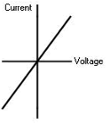
a resistor at constant temperature
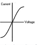
a filament lamp
a diode
explain how the design and use of circuits can be used to explore the variation of resistance in the following devices: filament lamps, diodes, thermistors, LDRs
filament lamps
connected to DC of 2,4,6…,10,12V
connect the filament lamp to Ammeter in series and Voltmeter in parallel
measure the current for each voltage
plot a graph to show relationship between the pd and current
non-linear shows resistance varies
diodes
connected to DC of 1,5,2,4,6,…,10,12V
connect to an Ammeter in series and Voltmeter in parallel
measure the current for each voltage
switch the diode the other way round to record current for -1,-1.5,-2,-4V
plot graph for the positive and negative potential differences to show the relationship
thermistor
constant velocity of 12V
connect to an Ammeter
place in ice water with thermometer
measure current at 0 degrees
add hot water and stir, measuring current at 10,20,….,60 degrees
calculate the resistance
plot a graph of resistance against temperature
LDR
constant voltage of 12V
connect to an Ammeter
shine lamp immediately onto LDR and measure current
keep doing this until 50cm
calculate resistance at each light intensity
plot graph of resistance against light intensity
what happens when there is an electrical current in a resistor
when there is an electric current in a resistor, there is an energy transfer which heats the resistor
as the result of collisions between electrons and the ions in the lattice
what happens to electrical energy when an electrical current does work against electrical resistance
electrical energy is dissipated as thermal energy in the surroundings when an electrical current does work against electrical resistance
ways of reducing unwanted energy transfer
low resistance wires made from metals such as copper, reduce unwanted energy transfer to thermal stores as the current flows between components
thicker wires can also be used as they have a lower resistance
also cooling metals reduce the resistance so the lattice ions are not vibrating as much
describe the advantages and disadvantages of the heating effect of an electric current
advantages
fuses use the effect to protect circuits - they melt and break the circuit if the current gets too high
the heating effect of the electric current is good if you want to heat something. there is a coil of high resistance wire which gives off infrared radiation, which transfers energy to the item needed to be heated (food)
disadvantages
heating up a component generally reduces its efficiency - less is transferred to useful energy stores as more is being transferred to the thermal store of the component
if the temperature gets too high, this can cause components in the circuit to melt. this will stop the circuit from working or work properly
equation for energy transferred
energy transferred (joule, J) = current (ampere, A) x potential difference (volt, V) x time (second, s)
E = I x V x t
what is power
power is the energy transferred per second and it measured in watt
power (watt, W) = energy transferred (joule, J)/ time taken (second, s)
P = E/t
power is directionally proportional to current and voltage, so doubling current doubles power
P = IV
electrical power (watt, W) = current (ampere, A) x potential difference (volt, V)
P = I² x R
electrical power (watt, W) = current² (ampere², A²) x resistance (ohm, Ω)
power loss is proportional to resistance, and to current²
energy is transferred from chemical potential in batteries to electrical energy in wires to any form of useful energy in the device they power
AC/DC
AC is alternating current, which come from the mains
current continuously varies, from positive to negative (charge changes direction)
DC, direction current, is the movement of charge in one direction only
cells and batteries supply direct current
in the UK, mains supply is at 50Hz and 230V
plug
in a plug there a 3 different wires: live wire, neutral wire and earth wire
live wire:
this is a brown colour
it carries voltage from mains to appliance
this may be dangerous even if mains circuit is off, as current may still be flowing through it
neutral wire:
this is a blue wire
completes the circuit
earth wire:
this has green and yellow stripes
it is the safety wire used to stop the appliance becoming live
it is connected to the earth and to the casing
if the live wire touches the metal casing of the appliance, it will become live (you’ll get a serious electric shock if you touch it, as current flows through you to the ground)
the earth wire is connected to the metal casing, and its low resistance means the current will go from the casing through the earth wire and to the ground
fuse
connected to the live wire
if a large current passes through live wire, fuse heats up and melts, breaking the circuit - preventing a fire or damage
explain the difference between direct and alternating voltage
in alternating voltage, the positive and negative ends of the p.d keep alternating
but in direct voltage, that is when the p.d is only positive or negative, not both
explain why switches and fuses should connected in the live wire of a domestic circuit
switches and fuses are connected in the live wire of the circuit so that the circuit can be broken - the appliance becomes isolated and the risk of an electric shock is reduced
recall the potential differences between the live, neutral and earth mains wires
potential difference between:
live and neutral - 230 V
live and earth - 230 V
earth and neutral - 0 V
describe the relationship between the power ratings for domestic electrical appliances and the changes in stored energy when they are in use
the power rating tells you the maximum amount of energy transferred between stores per second when the appliance is in use
eg. a microwave with a 500W will take longer to cook food than one with a power rating of 750W. this is because the 500W transfers less energy per second to the thermal energy store of the food, so it takes longer to cook