Software Architecture
1/20
There's no tags or description
Looks like no tags are added yet.
Name | Mastery | Learn | Test | Matching | Spaced |
|---|
No study sessions yet.
21 Terms
Hierarchical organisation of software
Data and memory
Algoritms
Objects
Modules
Componeny
System
System of systems
System decomposition
process of breaking down a complex system into smaller, more manageable components
Principles of System Decomposition
Modularity – divide-and-conquer
Abstraction – (Don’t re-invent the wheel) Focus on creative parts; if something already exists, reuse it
Encapsulation – Separation of concerns
Software Architecture
set of high-level decisions that determine the structure of the software solution
→Aim to use well-known solutions that are proven to work for similar problems
Key decisions in Software Architecture
System decomposition
• How do we break the system up into parts?
• What functionality/behavior to include?
• Do we have all the necessary parts?
• How do the parts interact?
Cross-cutting concerns
• Broad-scoped qualities or properties of the
system
• i.e. non-functional requirements
• Usually a trade-off between qualities
Conceptual integrity
• Does the system make sense?
Architecture vs Design
Architecture focuses on non- functional requirements and on the decomposition of a system
Design focuses on implementing functional requirements
Architectural Styles
a general, reusable solution to a commonly occurring problem in software architecture within a given context
→Different from, but related to, design patterns
Architectural Views
Views are different kinds of “blueprints” created for the system-to-be
4+1 Architectural View Model
Logical View
Development view
Process View
Physical view
Scenario view
Logical view
concerned with the functionality provided to users
→Focuses on the decomposition of the system into a set of key abstractions, namely objects and classes
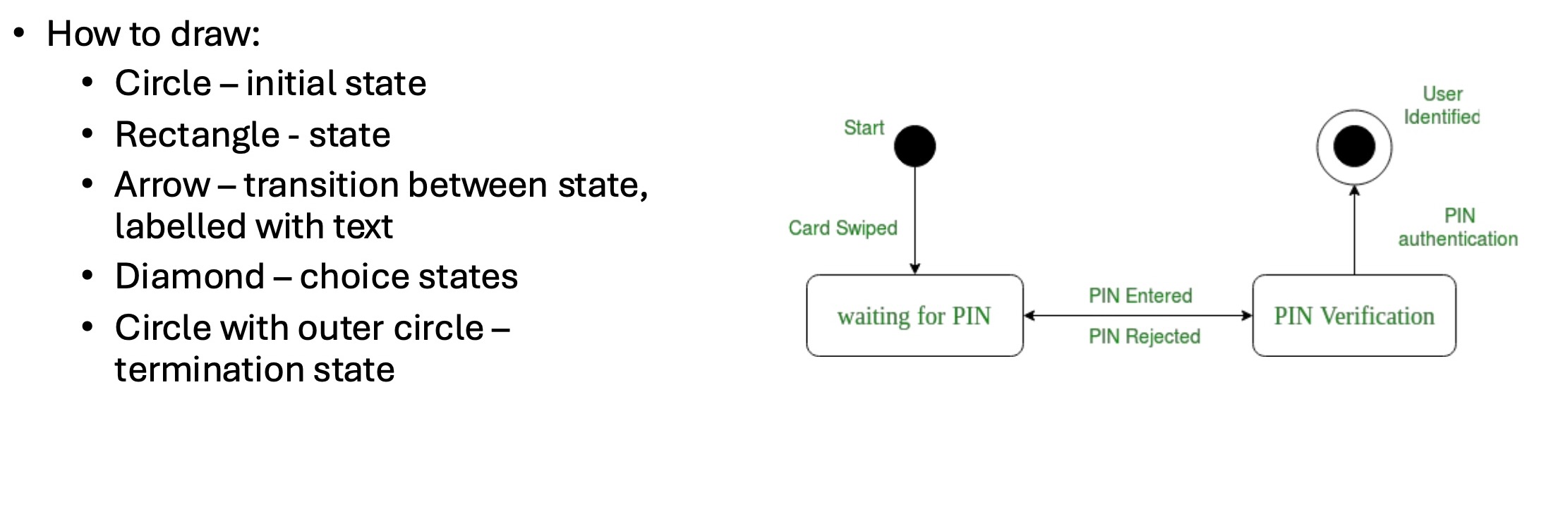
How is Logical view Represented in UML
Class diagram
State diagram: give a dynamic view of objects
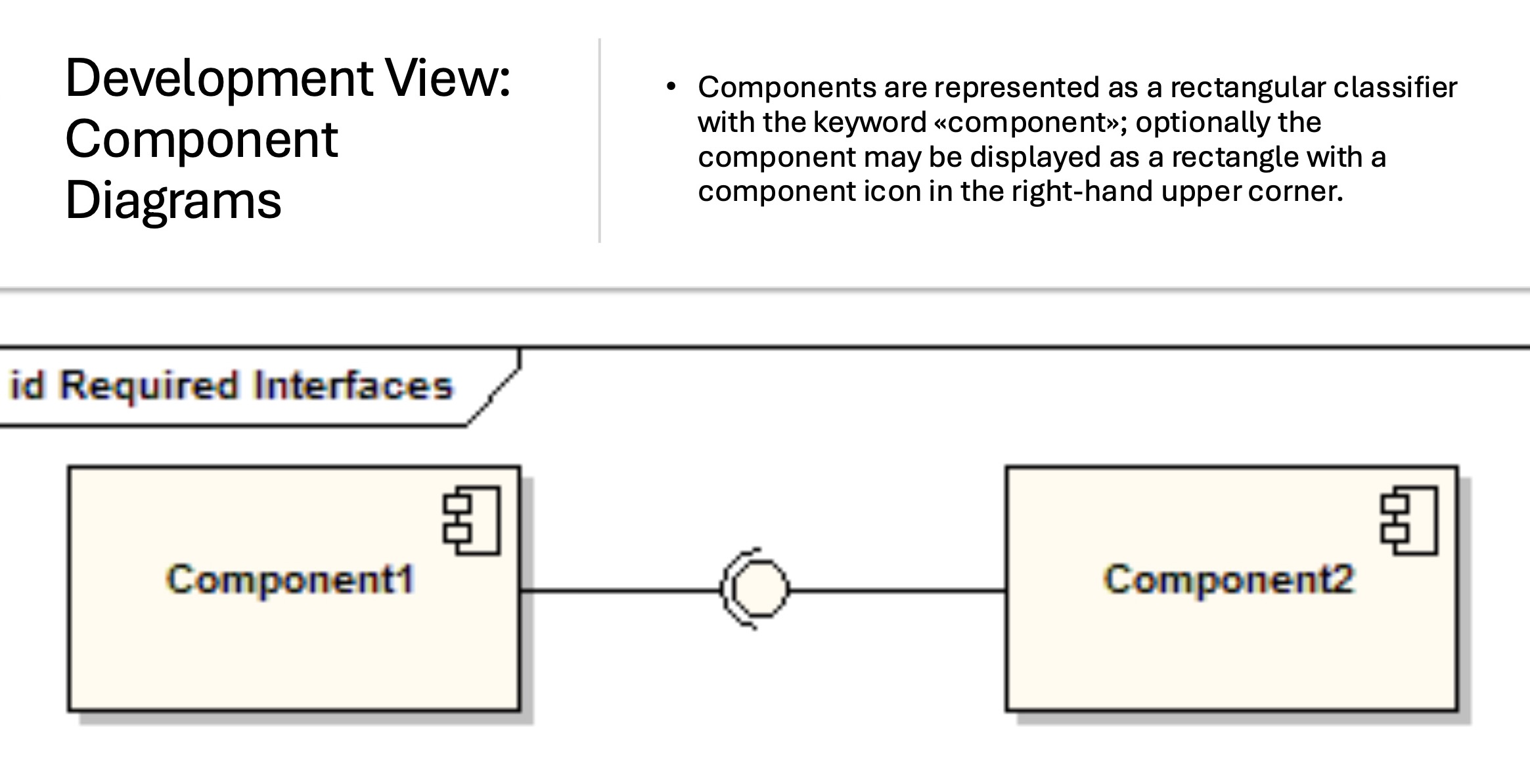
Development View
concerned with software administration from the point of view of the programmer
Focuses on components: modules of classes that represent independent systems or subsystems with the ability to interface with the rest of the system.
How do we represent Development View in UML
Component diagrams: show how different components in a system interact.
Process View
concerned with the dynamic aspects of the system, explaining the system processes and how they communicate
→Focuses on the runtime behaviour of the system
How is Process View represented in UML
Activity diagrams : show the workflow of a system
Sequence diagrams: show how components/objects in a system interact over time
Physical View
concerned with the physical distribution of the system, as well as the physical connections between distributed parts
→Depicts the system from the system engineer’s POV
Physical View UML Representation
Deployment diagrams: model the physical deployment of artifacts (software components) on nodes (hardware components)
Two types of nodes in deployment diagrams
Device nodes – physical devices that run software (computer, phone)
Execution Environment Node (EEN) – software resource that runs on a device and can execute other software (server, browser)
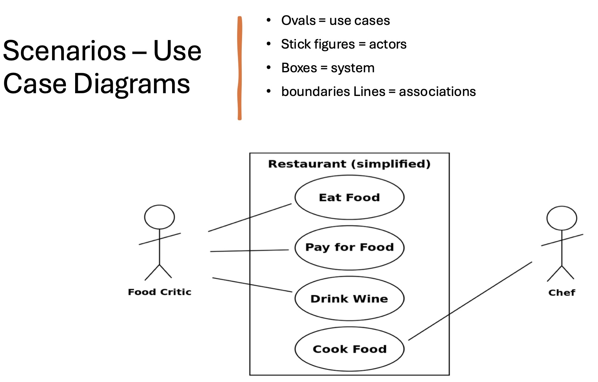
Scenario view
describe the system’s architecture through use cases– the list defining interactions between a role and a system to achieve some goal
Scenario view UML representation
use case diagrams
Drawing tools
Umbrello
Lucidchart