Operator controls
1/65
There's no tags or description
Looks like no tags are added yet.
Name | Mastery | Learn | Test | Matching | Spaced | Call with Kai |
|---|
No analytics yet
Send a link to your students to track their progress
66 Terms
Knobology
is the study of knobs or the functionality of controls
Monitor
Displays the ultrasound image with 2D, color and spectral doppler
Which part is near field and which part is far field
near field is on top and far field is on the bottom
power (dB)
Amplifies the sound into the patient; controls brightness
Determines the strength of the pulse sent into the human body
when the transmitted pulse is strong, the echos returning will be brighter
Generally, the preset is sufficient for imaging
ALARA
As low as reasonably achieveable
Low output power - high receiver gain
when the image is too bright
you can reduce the power (output)*
sector

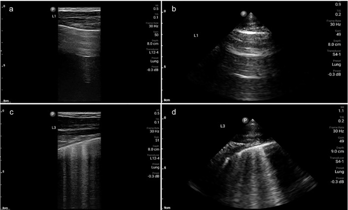
Linear array

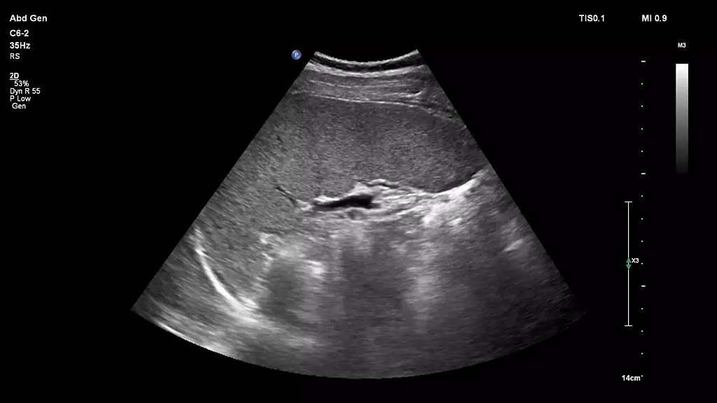
curved array

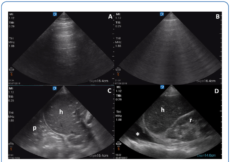
low frequency =
high pentration
high frequency =
low pentration
high frequencies
superficial structures
better resolution, but less penetration
low frequencies
deep structures
not as good resolution, but better penetration
Depth
Allows for adjustment of the image size
properly display body part being imaged
relational anatomy should be included
Harmonic imaging
frequency of the ultrasound pulse, which is twice the transmitted frequency, to create images. This technique improves image quality by enhancing contrast and resolution and reducing noise and artifacts,
overal Gain
“volume” control
Amplify sound
controls overall brightness of an image
time/depth gain compensation
Helps to create a uniform image by adjusting uneven brightness regardkess of depth
shallower structures will be brighter and deeper structures will be darker
compensate for attenuation that occurs with increasing depth
uses slide pods to control gain at different depths in specific regions of the image
Gain / TGC
should be adjusted so that tissue and its interfaces are recognizable
different tissues have different echo densities
Fat
Medium level gray; hyoechoic
different tissues have different echo densities
Fibrous tissue, ligaments, and skin
hyperechoic compared to fat
different tissues have different echo densities
calcifications
Markedly hyperechoic compared to fat
Fat
Medium level gray; hypoechoic
Muscle
Moderately hypoechoic compared to fat
Malignant solid nodules
midly to markedly hypoechoic compared to fat
simple cysts
markedly hypoechoic compared to fat and anechoic
Focal zone poition and number
tightest part of the ultrasound beam \beam is hourglass shaped
Focal zone is placed at or ?
below area of interest
focal zones
it will slow frame rate or image acquisition, but give bettter detail and resolution
the more focal zones used
the slower the frame rate
What is Dual image
displays 2 images side by side
image width
narrows swctor width
improves lateral resolutions
edges of masses are sharper
increased frame rate
able to steer the beam 90 degrees to structure
Improved reflection!
titnt/color maps - b-mode
colorization transforms the b-mode image from standard shades of gray to an alternative color display
Gain maps
Gray maps will add other levels of gray to the factory presets already in your machine
it provides subtle changes to the near or far fields
other maps change the shade of gray altogether
Dynamic range
Reflects the number of shades of gray that are displayed on the image
Also known as long compression
it is a function that varies to accommodate the range of intensities from the larhest to the smallest echo that the systen can handle
Low Dynamic range =
high contrast
less shades of gray
more blacks and whites
high Dynamic range =
low contrast
more shades of gray
allows for demonstration of subtle tissue contrast
contrast resolution
it is directly affected by the dynamic range setting on the ultrasound unit
if the dynamic range setting is set too low, the image contrast can make a solid structure appear cystic
is the dynamic range is set to high there is little contrast and a subtle mass may blend in with surrounding fat lobules
eedge enhancement
also known as sharpnes
a filtering technique that sharpens the image by identifying and enhancing the interfaces or boundaries between structures
leads to “crisper” images
smoothing
removes speckle noise from the ultrasound images
adjusting the image persistence causes individual frames of the scan to linger
persistence blends the individual frames with the images in the successive frames this creates — to the ultrasound image
increasing persistence will smooth the image but
reduces the system frame rate
decreasing persistence creates a more
pixilated/speckled image
what is the right way to zoom
is right zoom while the image is live
pre - processing
controlled by sonographer
altering data prior to it entering the machine
permanent and cant be changed
controls that cant be changed
post processing
controlled by sonographer
altering data after it enters the machine
these changes are not permanent
controls that can change a frozen image
read magnification
color maps
contrast variations
soft or lower contrast maps
sharper or higher contrast maps
controls that cant change a frozen image
TGC
write magnification
log compression
Doppler: detects movement of
RBC’s
color box
detects flow within region of interest (ROI)
size
should just contain the area of interest
too bigh = slows down frame rates
color gain
similar to b mode gain
SD - spectral doppler
Provides velocity or frequency shift information of blood flow on a graph
uses sample volume gate to obtain information
vascular: use an angle to flow
carfiac; no angle used
SD Gain
similar to B mode and CD gain
M-mode motion/time
information displayed runs along the cursor
depth is the vertrical axis
time is the horizontal axis
the echo brightness is related to the strength of the ref;ected echos
blood filled cavities should have no echoes
Freeze key
stops or starts the display image
allows for image capture
unfreezing returns to real time image
opportunity to annotate image, perform calculations store image
Trackball
guides cursor on the screen
can move the image through the different cycles imaged
positions measurement calipers
change size of scan area for zoom and color box size
cine loop
capture several images and sores them as a clip
image store / print
image capture button that saves image to hard drive
keybored
controls like annotation or comments on/off erase/clear.clear screen
backspace
new patient key /end
current patient
annotation
body marker labes are used for labeling anatomical structures
entering patients info
patient data is obtained from electronic medical records (EMR) and radiology info system (RIS)
ris
intergrates with the emr scheduling digital dictations and worklists
using the ultrasound system
select appropriate exam preset and transducer
exam preset
established baseline for that particular exam
step two transducer
high frequency transducer: small parts, thin patients, superficial structures; when detail is important
low frequency transducer; abdomen, OB/gyn, large patients; when penetration is needed
step 3 Gel application
gel is has inert properties
provides a media for sound waves to enter body
getting the image
1.adjust depth
2.Adjust focal zones: at or below area of interest
3.transducer frequency
4.adjust overall gain
5.adjust TGC
other technical adjustments
how to produce the best image possible
1.strong knowledge of anatomy and pathophysiology
2.patience and perseverance
3.understanding ultrasound physics
familiarization of the sonographic machine and controls