lecture 6 siemens combustion
1/14
There's no tags or description
Looks like no tags are added yet.
Name | Mastery | Learn | Test | Matching | Spaced |
|---|
No study sessions yet.
15 Terms
Tubular combustion chamber
A number of flame tubes are fitted inside a common air casing
▪ The arrangement combines the ease of overhaul and testing of multiple system with the compactness of annular system
▪ A major benefit for development is that a single can test rig may be similar to the engine design (except for can2can interaction)
▪ One draw back is the connection to the first turbine stage due to tangential variations and local hot and cold zones
Annular combustion chamber
The Annular Combustion Chamber consist of a single flame tube, completely annular in form, which is contained in an inner and outer casing
▪ Due to the less wall area a reduction of cooling air becomes possible which rise the combustion efficiency and save fuel and reduce air pollution
▪ May deliver a tangential uniform distribution that is a benefit for the turbine
▪ One drawback is that the flame zone boundaries are less defined compared to a can based system which could make the flames to interact
▪ Testing of burner configurations can be challenging since test rigs often are can based
Non-premixed combustion chamber
Air coming from the compressor enters the combustor casing at a velocity of >100 m/s
▪ Air speed has to be lowered to 20-30 m/s to prevent a flame blow out and a compressor diffusor is used to reduce pressure losses
▪ Air to fuel ratios depends on fuel type and combustion system: may vary between 15:1 up to 130:1
Fuel–air supply:
Compressed air enters the chamber from the compressor.
Fuel (e.g., natural gas, jet fuel) is injected separately through nozzles.
Mixing occurs inside the combustion chamber.
Combustion process:
The flame is mixing-controlled, not premixed.
Primary zone → rich mixture for stable ignition.
Secondary/dilution zones → additional air to complete combustion and reduce temperature.
Flame stabilization:
Achieved using swirlers and recirculation zones, which anchor the flame and sustain combustion.
Temperature control:
Staged air distribution avoids extremely high local temperatures.
Keeps turbine inlet temperature within material limits.
Advantages:
Simple and robust design.
Less flashback risk.
Compatible with liquid and gaseous fuels.
Pre-mixed combustion chamber
Aim of premixed combustors:
• As much air as possible through the burner
This to:
• Keep flame temperature low
• Thermal heat load even
• NOx emissions low
Too high temperature results in nox, to low leads to monoxide. Bypass valve takes heat from the flame and moves it downstream.
▪ Fuel and air are mixed before reactions take place
▪ Flame stabilizes where the flame propagation speed and the flow speed are the same
+ Possibility to have good carbon monoxide and nitrogen oxide emissions
- Combustion stability will depend on flame temperature, acoustics etc
Non Pre-Mixed Gas Turbine burner
Fuel is injected directly into the combustion chamber without being mixed with air in advance.
▪ Fuel is often injected in a swirling flow to achieve stable operation using limited space
▪ Much air is injected through the liner cooling and needs to mix with the hot combustion gases before entering the turbine
▪ Flame stability is generally very good but the NOx emissions are high
▪ Typical aero engine fuel injector
▪ Water injection can be used to reduce the NOx emissions
▪ Purified water required
▪ Fuel and air are introduced separately
▪ Combustion takes place at the stoichiometric mixing layer
+ High combustion stability
+ Low carbon monoxide emissions
- High nitrogen oxides (NOx) emissions
- High wall heat load close to the flame
Pre-Mixed Industrial gas turbine burner
Fuel and air is mixed in the burner cone and mixing tube before entering the combustion chamber.
Serial cooling system
▪ Often used in pre-mixed systems
▪ Air is first used for cooling and then used for combustion
▪ Higher pressure drop compared to parallel cooling
▪ Lower flame temperature compared to parallel cooling
Parallell cooling system
▪ Often used for “traditional” non-premixed systems but also for premixed systems
▪ Air from the compressor is divided between cooling air and combustion air
▪ Rather low pressure drop over the combustor
▪ Often higher flame temperature compared to serial cooling systems
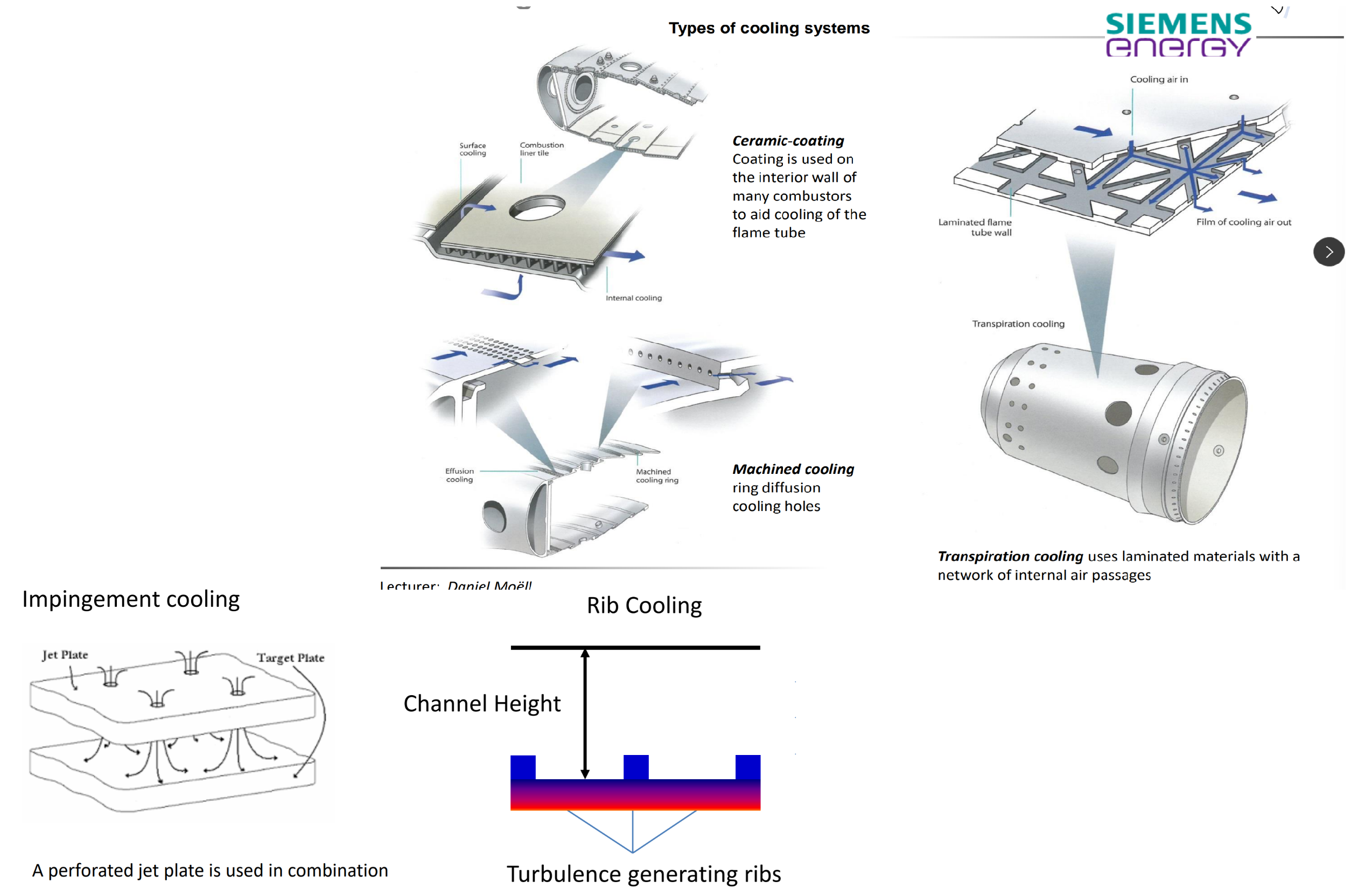
Types of cooling systems
Thermal expansion is unforgiving and is very important to keep under control. Therefore:
Ceramic-coating
Coating is used on the interior wall of many combustors to aid cooling of the flame tube
Machined cooling
ring diffusion and cooling holes
Transpiration cooling
uses laminated materials with a network of internal air passages
impingement cooling
A perforated jet plate is used in combination with a target plate that needs cooling. Typically used in parallell cooled systems.
Rib cooling
turbulence generating ribs, Air is passing through a cooling channel to cool a hot wall. To further enhance the cooling efficiency turbulence generating ribs can be used.
Effects of fuel change
combustion:
- Burner design
- Flashback/Flameout
- Ignition
- Atomization
- Flame temperature
- Dynamics
- Lifing
Exhaust:
- NOx
- CO
- SOx
- UHC
- Particles
Chemical reaction during combustion
combustion isnt just one reaction, but many intermediate components.
Chemical kineticts predicts the ratios of different molecules.
Yellow flame → soot
Blue flame → carbon radicals
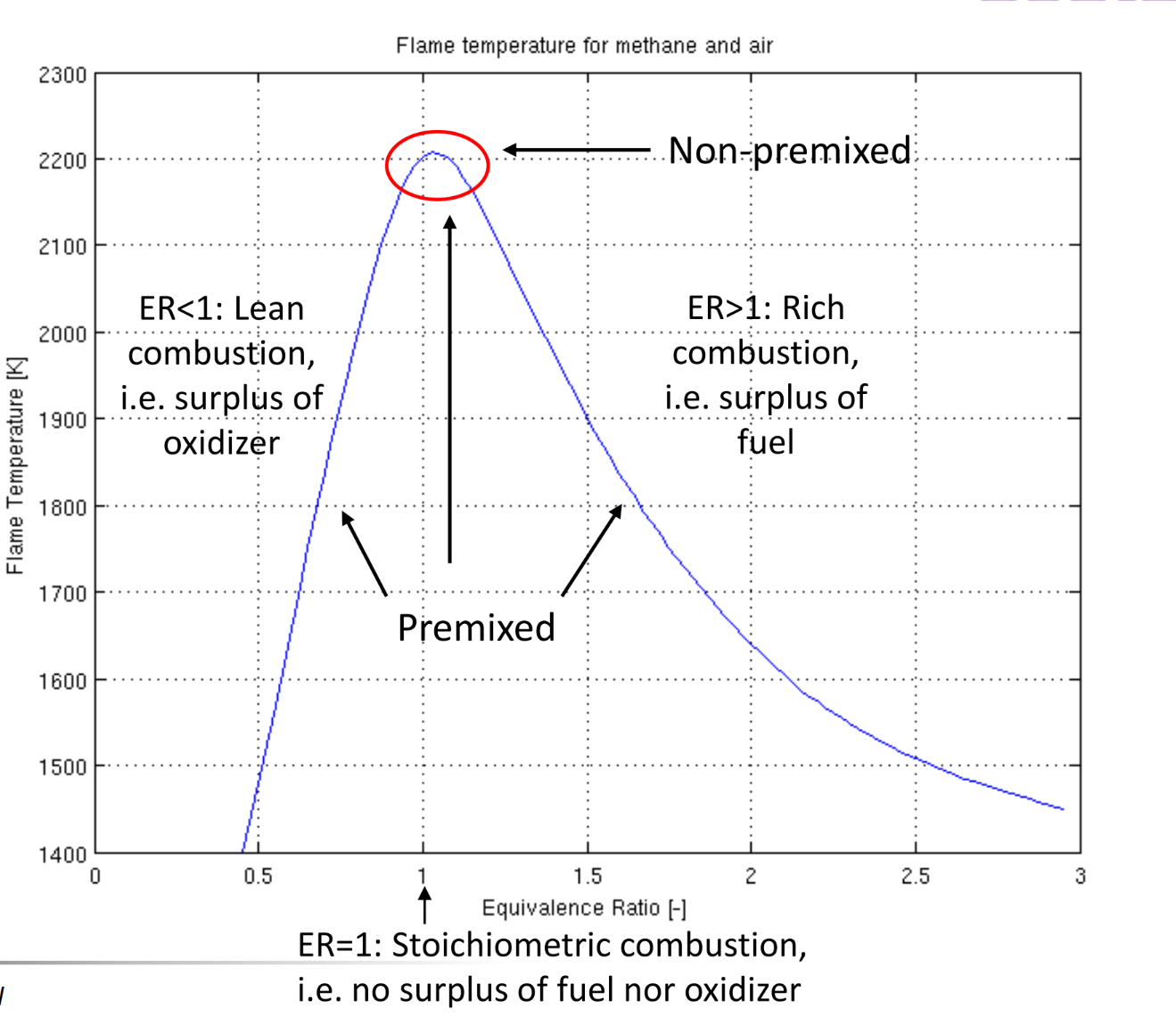
Combustion regimes
lean combustion: surplus of oxidiser
stochiometric combustion: perfect balance, all is consumed
Rich combustion: surplus of fuel
slightly lean is preferable with NG etc.
Rich is preferable for ammonia
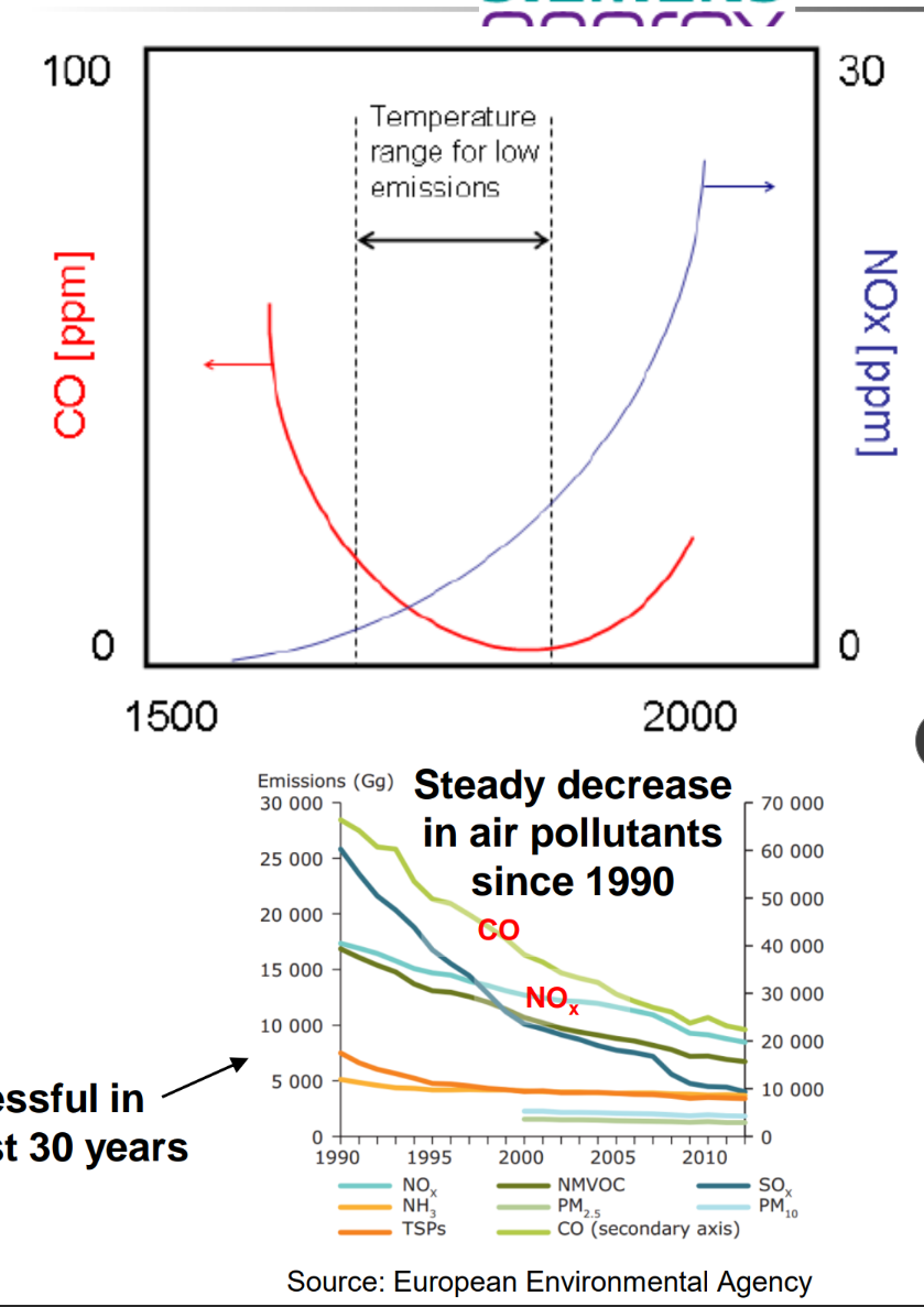
Emissions
Typical gas turbine emissions are:
▪ CO2 (Carbon dioxide)
The Carbon dioxide, CO2, is a un-avoidable combustion product when using hydrocarbons as fuel. The only way to reduce the CO2 emissions is either to use Hydrogen, H2, as fuel or to increase the overall efficiency on the gas turbine.
▪ CO (Carbon monoxide)
▪ NOX
(NO and NO2)
CO and NOX emissions are mainly affected by:
➢ the flame temperature
➢ the residence time
CO reduces at higher temperatures whereas NOX increases with higher temperatures
Gas turbines have been successful in reducing NOx and CO for the last 30 years
Combustion instabilities
Heat release oscillations, Acoustic oscillations, flow and mixture perturbations
Thermo-acoustic instabilities (Higher frequency band)
▪ Typical in premixed combustion at leaner mixtures at higher pressures
Further combustion instability:
▪ Extinction and relight (Lower frequency band)
▪ Flow induced instabilities
Use of passive dampening can be necessary, oscillations can break components.
Combustion instabilities
▪ Need time to develop
▪ Seconds or months
May be avoided by damping systems or by operation control
▪ Adjusted staging: emission penalty
▪ Load adjustment: operation penalty
Measurements
Measurements inside GT combustors are difficult due to harsh environment
• High pressure and temperature
Some techniques used for measurements in GT combustion chambers are:
• Temperature measurements using thermocouples for walls and flow
• Wall temperature distribution using thermal paint
• Static and total pressure to estimate mass flow distribution
• Dynamic pressure measurements using high speed pressure transducers
• Flame visualization using borescope
Additional techniques used for measurements in turbulent combustion in rigs are:
• Velocity measurements using laser diagnostics (PIV,LDA)
• Species and T measurements using laser diagnostics (PLIF, RAMAN, Rayleigh)