AutoCAD 2024: Measurement, Modification, and Drawing Commands Overview (copy)
1/389
There's no tags or description
Looks like no tags are added yet.
Name | Mastery | Learn | Test | Matching | Spaced | Call with Kai |
|---|
No analytics yet
Send a link to your students to track their progress
390 Terms
MEASURE (Command)
Creates point objects or blocks at measured intervals along the length or perimeter of an object.
Orientation of Points/Blocks
The orientation is determined by the XY plane of the UCS.
PTYPE
Use PTYPE to set the style and size of all point objects in a drawing.
Previous Selection
The points or blocks are placed in the Previous selection.
Node Object Snap
You can use the Node object snap to draw an object by snapping to the point objects.
Object to Measure
Select the reference object along which you want to add the point objects or blocks.
Length of Segment
Places point objects at the specified interval along the selected object, starting at the endpoint closest to the point you used to select the object.
Measurement of Closed Polylines
Starts at their initial vertex (the first one drawn).
Measurement of Circles
Starts at the angle from the center set as the current snap rotation angle.
PDMODE System Variable
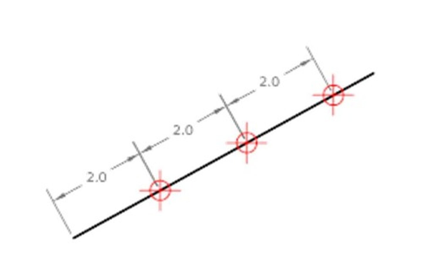
The illustration shows how MEASURE marks 0.5-unit distances along a polyline, with the PDMODE system variable set to 35.
Block
Places blocks at a specified interval along the selected object.
Align Block with Object - Yes
The block is rotated about its insertion point so that its horizontal lines are aligned with, and drawn tangent to, the object being measured.
Align Block with Object - No
The block is always inserted with a 0 rotation angle.
DIVIDE (Command)
Creates evenly spaced point objects or blocks along the length or perimeter of an object.
Select Object to Divide
Specifies a single geometric object such as a line, polyline, arc, circle, ellipse, or spline.
Number of Segments
Places point objects at equal intervals along the selected objects. The number of point objects created is one less than the number of segments that you specify.
Align Blocks - Yes
Aligns the blocks according to the curvature of the selected object.
Align Blocks - No
Aligns the blocks according to the current orientation of the user coordinate system.
DIST (Command)
Measures the distance and angle between two points.
Access Method for DIST
'DIST for transparent use.
3D Distances in Model Space
In general, the DIST command reports 3D distances in model space and 2D distances on a layout in paper space.
Elevation Assumption
DIST assumes the current elevation for the first or second point if you omit the Z coordinate value.
Specify First and Second Point
Specifies two points between which you want to get the distance and angle.
Multiple Points
Specifies several points, recording a running total of the distance.
SCALE (Command)
Enlarges or reduces selected objects, keeping the proportions of the object the same after scaling.
Base point (SCALE)
Acts as the center of the scaling operation and remains stationary.
Scale factor
Multiplies the dimensions of the selected objects by the specified scale.
Copy (SCALE)
Creates a copy of the selected objects for scaling.
Reference (SCALE)
Scales the selected objects based on a reference length and a specified new length.
ROTATE (Command)
Rotates objects around a base point.
Rotation Angle
Determines how far an object rotates around the base point.
Copy (ROTATE)
Creates a copy of the selected objects for rotation.
Reference (ROTATE)
Rotates objects from a specified angle to a new, absolute angle.
MOVE (Command)
Moves objects a specified distance in a specified direction.
Base point (MOVE)
Specifies the start point for the move.
Second point (MOVE)
Specifies a vector that indicates how far, and in what direction, the selected objects are moved.
Using a Specific Coordinate
Type the pound sign (#) followed by the X-value, a comma, then the Y-value, for example #4.0,6.75.
Using a Relative Coordinate
Specifies the distance and direction from the previous coordinate.
Displacement
Specifies a relative distance and direction.
EXTEND (Command)
Extends objects to meet the edges of other objects.
Quick Mode (EXTEND)
One of the two modes that you can use to extend objects.
Standard Mode (EXTEND)
The second mode that you can use to extend objects.
Quick mode
Options that allow for fast selection and extension of objects.
Cutting edges
Uses additional selected objects to define the boundary edges for extending an object.
Fence
Selects all objects that cross the selection fence, which is defined by two or more points.
Crossing
Selects objects within and crossing a rectangular area defined by two points.
Mode
Sets the default extend mode to either Quick or Standard.
Project
Specifies the projection method used when extending objects.
None
Specifies no projection; only objects that intersect with the boundary edge in 3D space are extended.
UCS
Specifies projection onto the XY plane of the current user coordinate system.
View
Specifies projection along the current view direction.
Edge
Extends the object to another object's implied edge or to an object that intersects it in 3D space.
Extend
Extends the boundary object along its natural path to intersect another object or its implied edge in 3D space.
No Extend
Specifies that the object is to extend only to a boundary object that actually intersects it in 3D space.
Undo
Reverses the most recent changes made by the EXTEND command.
CHANGE (Command)
Changes the properties of existing objects.
Specify Objects
Prompts the user to select objects to change.
Change Point or Values
Changes the selected objects based on the type of objects selected.
Lines
Moves the endpoints of selected lines closest to the change point to the new point.
Circles
Changes the radius of the selected circle.
Circle Radius
Changes the circle radius. If you selected more than one circle, the prompt is repeated for the next circle.
Text
Changes text location and other properties.
Specify New Text Insertion Point
Relocates the text.
Attribute Definitions
Changes the text and text properties of an attribute that is not part of a block.
Blocks
Changes the location or rotation of a block.
Properties
Modifies properties of existing objects.
Plotstyle Option
The Plotstyle option is displayed only when you are using named plot styles.
Color
Changes the color of the selected objects.
True Color
Specifies a true color to be used for the selected object. The integer values range from 0 to 255 separated by commas.
Color Book
Specifies a color from a loaded color book to be used for the selected object.
Elev
Changes the Z-axis elevation of 2D objects.
Layer
Changes the layer of the selected objects.
Ltype
Changes the linetype of the selected objects.
Ltscale
Changes the linetype scale factor of the selected objects.
Lweight
Changes the lineweight of the selected objects. Lineweight values are predefined values.
Thickness
Changes the Z-direction thickness of 2D objects.
Transparency
Changes the transparency level of selected objects.
Material
Changes the material of the selected objects if a material is attached.
Annotative
Changes the annotative property of the selected objects.
Chamfer (Command)
Bevels or chamfers the edges of two 2D objects or the adjacent faces of a 3D solid.
Bevel or Chamfer
An angled line that meets the endpoints of two straight 2D objects or a sloped transition between two surfaces or adjacent faces on a 3D solid.
Create 2D Chamfer
A bevel or chamfer can be defined by selecting two objects of the same or different object types: lines, polylines, rays, and xlines.
First Line
Select the first of two objects or the first line segment of a 2D polyline to define the chamfer.
Second Line or Shift-Select to Apply Corner
Select the second object or line segment of a 2D polyline to define the chamfer.
Adjacent Line Segments
If the selected objects are straight line segments of a 2D polyline, the line segments can be adjacent to each other or separated by one other segment.
Chamfer
A bevel added to the edge of an object.
Hatch Associativity
The relationship that allows a hatch to update when its boundary changes.
Polyline
Inserts a chamfer line at each vertex of a 2D polyline where two straight line segments meet.
Trim
Controls whether the selected objects are trimmed to meet the endpoints of the chamfer line.
Distance
Sets the chamfer distances from the intersecting points of the first and second objects.
Angle
Sets the chamfer distance from the intersecting point of the selected objects and the XY angle from the first object or line segment.
Method
Controls how the chamfer line is calculated from the intersecting point of the selected objects or line segments.
Multiple
Allows for the beveling of more than one set of objects.
Create 3D Chamfer
A chamfer can be added along the edge of a 3D solid or surface.
Surface Selection Option
Indicates which adjacent surface is the base surface for chamfering.
Chamfer Distance
Sets the chamfer distances for the base and other adjacent surfaces.
Expression
Controls the chamfer distance with a mathematical expression.
Loop
Enables sequential tangent edge selection mode.
Fillet (Command)
Rounds or fillets the edges of two 2D objects or the adjacent faces of a 3D solid.
Round or Fillet
An arc that is created tangent between two 2D objects.