Capacitance questions
1/28
Earn XP
Description and Tags
Name | Mastery | Learn | Test | Matching | Spaced | Call with Kai |
|---|
No analytics yet
Send a link to your students to track their progress
29 Terms
A capacitor gains 300 μC of negative charge on one of its plates. How much charge does it store?
300 μC
A 200 nF capacitor is charged by connecting it across a p.d of 6V. How much charge does it store?
Q = CV = 200x10-9 × 6.0 C = 1.2 μC
A 200 nF capacitor is charged by connecting it across a p.d of 6.0 V. It is disconnected. How much total charge remains on the capacitor?
Charge remains
1.2 μC
A 200 nF capacitor is charged by connecting it across a p.d of 6.0 V. It is disconnected and then reconnected across 9.0 V. How much total charge remains on the capacitor?
Q=CV=200x10-9 × 9.0 = 1.8 μC
A capacitor is charged such that there is a charge of +20 mC on the positive plate. What is the charge on the negative plate?
- 20 mC
Equal and opposite charge
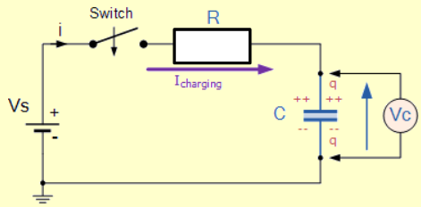
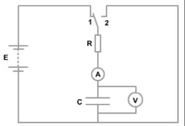
Draw a circuit to show how you can charge a capacitor, C, through a fixed resistor, R, and measure the current in the circuit, I, and the potential difference across the capacitor, VC
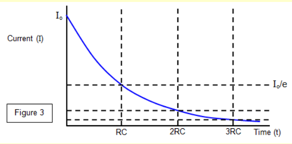
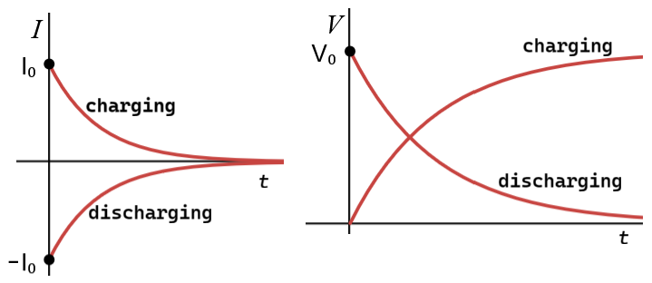
Sketch a graph of how I varies with time, t for a capacitor being charged through a thixed resistor
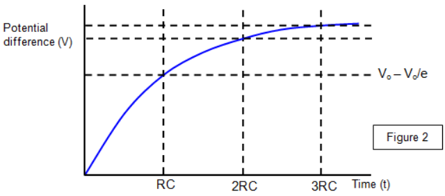
Sketch a graph of how VC varies with t for a capacitor being charged through a thixed resistor
For each process of charging and discharging:
a) Identify the position of the switch in the circuit
b) Sketch the I-t and V-t curves
c) Write down the equations for I and V as a function of t
d) We know R. How could we determine C from our data? There is more than one possible method
a) Charging when switch at position 1, discharging when at position 2
b) See image
c) Charging: I = I0 e-t / RC, V = V0 e-t / RC
Discharging: I = −I0 e-t / RC, V = V0 (1 - e-t / RC)
d) use time constant
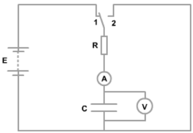
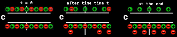
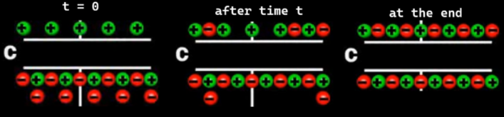
The capacitor C is charged by the circuit shown. Draw sketches of the charge on the plates
a. At the start t=0s
b. After a time t
c. At the end (when no further change is detected)

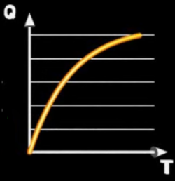
Sketch the Q-t, charge versus time, plot and state the equation for the capacitor C being charged
Q = Q0(1- e-t/RC)

The capacitor C is discharged by the circuit shown. Draw sketches of the charge on the plates
a. At the start t=0s
b. After a time t
c. At the end (when no further change is detected)

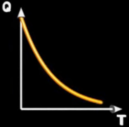
Sketch the Q-t, charge versus time, plot and state the equation for the capacitor C being discharged
Q = Q0 e-t/RC
Write down the equation that relates I to Q. How can we determine the initial charge Q0 from a I-t discharge plot?
I = ΔQ / Δt
Multiply both sides by Δt: ΔQ = I Δt. This is equivelent to dQ = I dt
∫ 1 dQ = ∫ I dt ⇒ Q = ∫ I dt. As such Q0 is the area under the I-t discharge plot.
Write down an equation that relates Q to V for a capacitor. How can we determine Q and Q0 from our V-t data?
C = Q / V
Hence Q = VC
To get Q at time t, multiply V at that time by C.
To get Q0, multiply V0 by C.
A capacitor 1000μF is discharging through a resistor 100kΩ. The time for the current to fall to 7/8th of its original value is
13
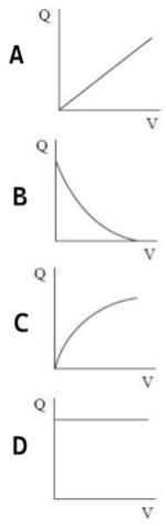
An uncharged capacitor is connected to a battery. Which graph shows the variation of charge with potential difference across the capacitor?
A
A 100 nF capacitor is connected in series 1 MΩ resistor. A p.d of 6 V is applied across the circuit. What is the initial current?
6 μA
A 220 pF capacitor is connected in series 1000 MΩ resistor. A p.d of 5 V is applied across the circuit. How much charge will the capacitor store when fully charged?
1.1 nC
A capacitor 420 μF is discharging through a resistor 200 kΩ. What is the time constant?
84 s
A capacitor is discharging through a resistor and the time constant is 5.0 s. The time taken for the capacitor to lose half its charge is
3.5 s
The voltage across the plates of a capacitor is measured at 10s intervals when it is discharging through a resistor. The ratio of the initial voltage to next voltage reading is 1.4. The third reading to the forth reading is
1.4
What is the current flowing in an RC discharging circuit, when the charge stored on the plates is 310μC and the values of C and R are 470 μF and 330kΩ respectively
2μA
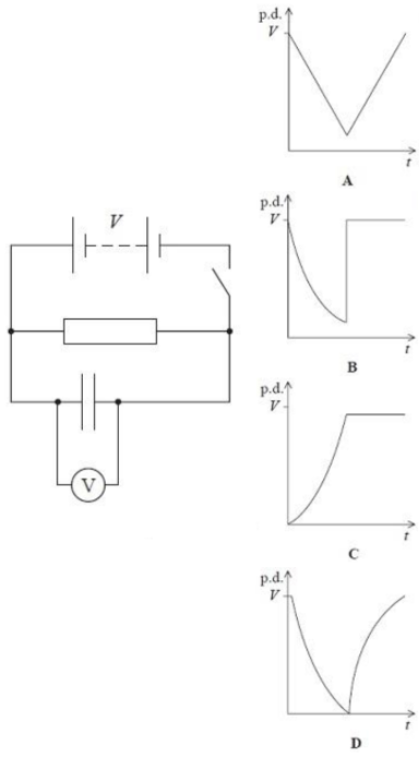
The capacitor shown in the circuit below is initially charged to a potential difference (p.d.) V by closing the switch. The power supply has negligible internal resistance.
The switch is opened and the p.d. across the capacitor allowed to fall. A short time later the switch is closed again. Select the graph that shows how the p.d. across the capacitor varies with time, after the switch is opened.
B
A charged 700nF capacitor is connected across two 10MΩ resistor connected in parallel. The half -life for the circuit is
2.4 s
A capacitor 2000μF is discharging through a resistor 30kΩ. The time for the capacitor to lose 7/10ths of its charge is
72s
A p.d of 9V is applied across an RC circuit in which a capacitor 320μF is connected in series with a resistor 100kΩ. How much charge is stored on the plates of the capacitor when the current reaches 20μA?
2.2mC
Explain why a capacitor cannot be charged directly from the mains supply.
Capacitors need d.c. but mains is a.c.
Charge given in one half of cycle is removed the next half
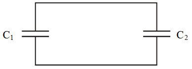
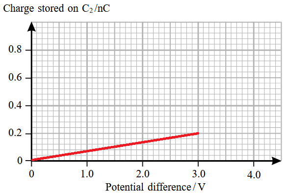
Capacitor C1 has capacitence 0.80nC. It is charged to 4.0V. An uncharged capacitor C2 is connected in its place as shown. Capacitor C1 transfers some of its charge to the plates of capacitor C2. As a result the potential difference across C1 falls to 3.0 V. Draw a current time graph to show how the charge stored on capacitor C2 varies with potential difference during this charge transfer process.
Charge transferred to C2 = 0.2nC
Straight and through origin
Must end at 3.0V and 0.2nC