3.3.2 - Refraction, Diffraction & Interference
5.0(1)
Studied by 4 peopleCard Sorting
1/40
Earn XP
Description and Tags
Last updated 4:53 PM on 1/20/23
Name | Mastery | Learn | Test | Matching | Spaced | Call with Kai | Chat |
|---|
No analytics yet
Send a link to your students to track their progress
41 Terms
1
New cards
Refractive Index (n)
A measure of the relative speed of light in a material compared to in a vacuum (3 x 10^8 ms^-1)
2
New cards
Refraction
Light changing velocity when it travels across the boundary between two materials.
\
A more optically dense material (higher refractive index) causes it to slow down and bend towards the normal and vice versa.
\
A more optically dense material (higher refractive index) causes it to slow down and bend towards the normal and vice versa.
3
New cards
What changes when a wave refracts?
Wave speed and wavelength change.
\
Frequency stays the same
\
Frequency stays the same
4
New cards
Calculating Refractive Index
n = c (vacuum) / c (material) = λ (vacuum) / λ (material
5
New cards
Refractive index of air
Air is considered a vacuum as it doesn’t slow light down significantly so has a ^^refractive index of one^^
6
New cards
Snell’s Law
n1 sinθ1 = n2 sinθ2
\
* n1 is the refractive index of material 1
* n2 is the refractive index of material 2
* θ1 is the angle of incidence of the ray in material 1
* θ2 is the angle of refraction of the ray in material 2
\
* n1 is the refractive index of material 1
* n2 is the refractive index of material 2
* θ1 is the angle of incidence of the ray in material 1
* θ2 is the angle of refraction of the ray in material 2
7
New cards
Total Internal Reflection
All light gets reflected off of a surface instead of passing through and being refracted.
8
New cards
TIR - Conditions
* Light has to be more from a more optically dense medium (higher n value) into a less optically dense medium (lower n value).
\
* Angle of Incidence > Critical angle
\
* Angle of Incidence > Critical angle
9
New cards
Critical Angle
The angle of incidence which causes light to travel alongside the boundary due to an angle of refraction = 90\*
10
New cards
Critical Angle Formula
sinθ c = n2 / n1
\
where n1 > n2
\
where n1 > n2
11
New cards
Uses of TIR
TIR is used in optical fibres which carry information in the form of light signals.
12
New cards
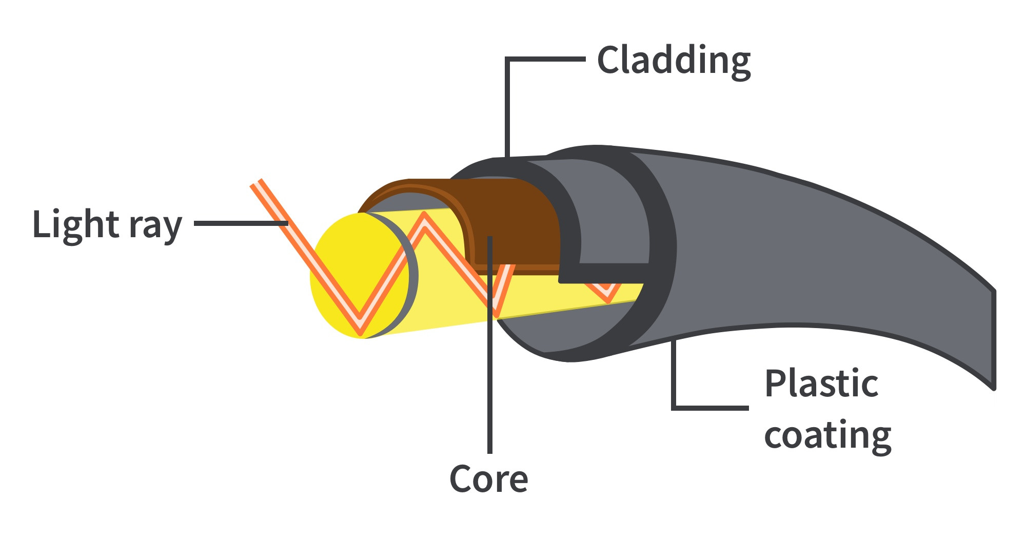
How do optical fibres work?
A light pulse is sent down an optical fibre and is detected at the other end generating a signal.
13
New cards
Optical Fibre Structure
Flexible thin tube of plastic or glass.
\
Inner core is more optically dense and surrounded by cladding which is less optically dense
\
Inner core is more optically dense and surrounded by cladding which is less optically dense
14
New cards
Function of cladding
* protects the core from damage
\
* prevents signal degradation through light escaping the core, which can cause information to be lost
\
* prevents signal degradation through light escaping the core, which can cause information to be lost
15
New cards
Signal Degradation causes -
* Absorption
* Dispersion
* Dispersion
16
New cards
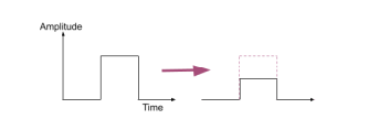
Absorption
Parts of the signal’s energy is absorbed by the fibre reducing the overall amplitude of the signal - could cause a loss of information
17
New cards
Dispersion
Causes Pulse Broadening which is when the received signal is broader then the original transmitted signal - broadened signals can overlap which causes loss of information.
\
\
18
New cards
Types of dispersion
* Modal
* Material
* Material
19
New cards
Modal Dispersion - what is it?
Light rays enter fibre at different angles so take different paths hence they could take different amounts of time to travel along the fibre
20
New cards
Modal Dispersion - How to reduce it?
Make the core very narrow to reduce the possible path differences the light could have.Mater
21
New cards
Material Dispersion - what is it?
Light consisting of different wavelengths will travel at different speeds in a material
22
New cards
Material Dispersion - How to reduce it?
Use monochromatic light
23
New cards
Path difference
The difference in the distance travelled by two waves
24
New cards
Coherent Light Source
A light source where all light waves emitted have the ^^same frequency and wavelength^^ with a ^^constant phase difference.^^
25
New cards
Monochromatic light
Light of a single wavelength
26
New cards
Young’s Double Slit Experiment purpose
To demonstrate the wave properties of light.
27
New cards
How to make a light source cohesive
* Place single slit before a double slit to make the light have a constant phase difference
\
* Use a filter to make the light monochromatic
\
* Use a filter to make the light monochromatic
28
New cards
What did young’s double slit experiment show?
A series of bright (maxima) and dark (minima) fringes - the central fringe is always a bright fringe.
\
The path difference for light from one slit is different from the other slight so light meets on the screen in different phases.
\
The path difference for light from one slit is different from the other slight so light meets on the screen in different phases.
29
New cards
Bright Fringes - causes
Light meets in phase and interferes constructively which occures when the path difference is a whole number of wavelengths (^^nλ^^).
30
New cards
Dark Fringes - Causes
Light meets out of phase and interferes destructively which occurs when the path difference is a whole number and a half wavelengths (^^(n+½)λ^^).
31
New cards
Young’s double slit equation
sw = λD
\
where -
* s = slit separation (m)
* w = fringe separation (m)
* λ = wavelength (m)
* D = distance from screen (m)
\
slit separation is measured from the centre of one slit to the centre of the next
\
where -
* s = slit separation (m)
* w = fringe separation (m)
* λ = wavelength (m)
* D = distance from screen (m)
\
slit separation is measured from the centre of one slit to the centre of the next
32
New cards
Diffraction
The spreading out of waves as they pass through or around a gap.
\
The greatest diffraction occurs when the gap is the same size as the wavelength - when the gap is smaller most waves get reflected.
\
The greatest diffraction occurs when the gap is the same size as the wavelength - when the gap is smaller most waves get reflected.
33
New cards
Single Slit Diffraction Pattern
A bright(est) central fringe double the width of all the other fringes with alternating dark and bright fringes on either side.
\
Intensity of fringes decreases from central fringe,
\
Intensity of fringes decreases from central fringe,
34
New cards
Singe slit - changing slit width
Increasing slit width = less diffraction so central maxima is narrower and more intense
35
New cards
Single Slit - changing wavelength
Increasing the wavelet will increase how much light diffracts causing a thicker less intense central maxima
36
New cards
White light single slit
\
37
New cards
White light double slit
38
New cards
Diffraction Grating Pattern
More distinct dark and bright fringes.
\
The central fringe is called the zero order line and then the first order lines and then the second order lines etc.
\
The central fringe is called the zero order line and then the first order lines and then the second order lines etc.
39
New cards
What is a diffraction grating?
A slide containing many equally spaced slits.
\
d = 1/N
\
where -
* d = distance between the slits
* N = number of slits ^^per metre^^
\
d = 1/N
\
where -
* d = distance between the slits
* N = number of slits ^^per metre^^
40
New cards
Diffraction Grating equation
d sinθ = nλ
\
where -
* d = distance between the slits
* θ = the angle between the zero order line and next order line
* n = the order
* λ = the wavelength
\
where -
* d = distance between the slits
* θ = the angle between the zero order line and next order line
* n = the order
* λ = the wavelength
41
New cards
Diffraction Grating - changing wavelength