Electricity
1/64
Earn XP
Name | Mastery | Learn | Test | Matching | Spaced | Call with Kai |
|---|
No analytics yet
Send a link to your students to track their progress
65 Terms
Electrical Current (definition, units)
The rate of flow of charge.
Measured in ampères(A)
Normally a flow of electrons in metals or a flow of ions in electrolytes
Equation for electrical current with t in it
I = ΔQ/Δt = charge transfered (coloumbs) / time (seconds)
Charge of an electron
-1.6×10⁻¹⁹ Coulombs (=-e)
Value of elementry charge
1.6×10⁻¹⁹ C
Kirchhoff’s 1st law
At any point in an electrical circuit, the sum of currents into that point is equal to the sum of currents out of that point
What physical quantity is conserved according to Kirchhoff’s 1st law?
Charge
Conventional current
The ‘flow of positive charge’ - it is in the opposite direction to the movement of the electrons in the circuit.
What is mean drift velocity? Why is it an average?
The average velocity of the charge carriers due to the applied electric field. It has to be an average because individual charge carriers are often moving randomly in all directions.
Equation linking current and drift velocity
I = Anev
Current = Cross-sectional area × number density × elementry charge × mean drift velocity
Number density
Number of charge carriers per metre3
Potential difference
The energy per unit charge transferred from electrical energy to other forms (heat, light, etc.)
Volt
1 V is the p.d. across a component when 1 J of energy is transferred per 1 coulomb passing through the component
The energy transferred per unit charge.
Unit of p.d. and e.m.f
Electromotive force (e.m.f)
The energy transferred per unit charge from chemical energy (or other forms like light, heat, movement etc.) to electrical energy
Kirchhoff’s 2nd law
In a closed loop of an electrical circuit, the sum of the e.m.f.s is equal the sum of the p.d.s
What physical quantity is conserved according to Kirchhoff’s 2nd law?
Energy
Equation for total resistance of resistors in series
RT = R1 + R2 + …
Equation for total resistance of resistors in parallel
1/RT = 1/R1 + 1/R2 + …
Ohm’s law
The potential difference across a conductor is directly proportional to the current in it as long as its temperaure remains constant
V = IR is not an expression of ohms law
Equation linking resistance and resisivity (symbol & word)
R=ρL/A
Resistance(Ω) = resistivity(Ωm) × length of wire(m) / cross-sectional area(m2)
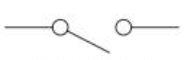
(open) switch circuit symbol
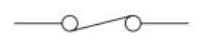
(closed) switch circuit symbol
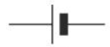
Cell circuit symbol
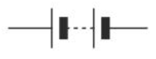
Battery circuit symbol
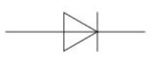
Diode circuit symbol
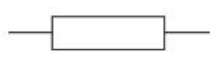
Resistor circuit symbol
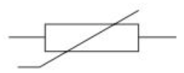
Variable resistor circuit symbol

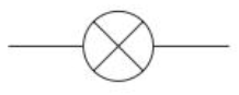
Lamp circuit symbol
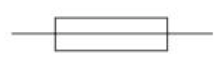
Fuse circuit symbol
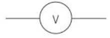
Voltmeter circuit symbol
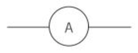
Ammetre circuit symbol
Thermistor circuit symbol
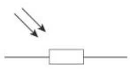
Light dependant resistor (LDR) circuit symbol
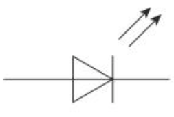
Light emitting diode (LED) circuit symbol
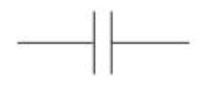
Capacitor circuit symbol
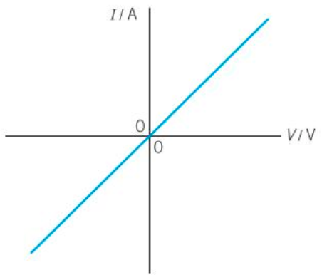
IV characteristics of resistors
P.d. is directly proportional to the current through it (V∝I).
Ohmic conductor
The resistance is constant.
The resistor behaves in the same way regardless of the polarity.
IV characteristics of filament lamps
P.d. is not directly proportional to the current through it.
non-ohmic component
the resistance is not constant.
Behaves in the same way regardless of the polarity.
Resistance of the filament lamp increases as the p.d. across it increases
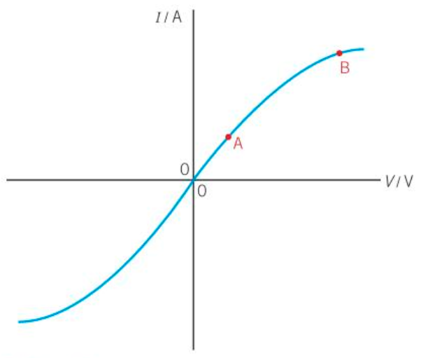
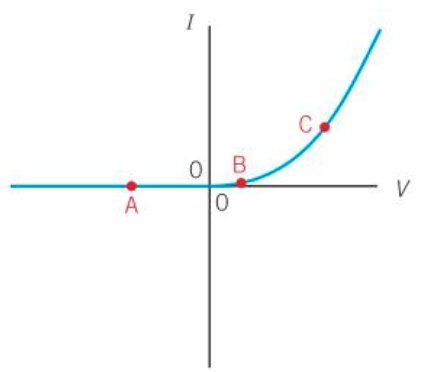
IV characteristics of diodes
P.d. is not directly proportional to the current through it.
non-Ohmic component
the resistance is not constant.
The diode’s behaviour depends on the polarity.
Below the threshold p.d. the resistance is very high - infinite for practical purposes (e.g. at A)
At the threshold p.d. (at B) the resistance gradually starts to drop.
Above the threshold p.d. the resistance drops rapidly (e.g. at C) and the diode has very little resistance.
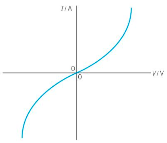
IV characteristics of thermistors
P.d. not directly proportional to current. As such:
it is a non-ohmic component
resistance is not constant
Behaves in the same way regardless of the polarity.
Resistance of the thermistor decreases as current increases.
Temperature increases as current increases.
This causes an increase in number density and so a drop in resistance.
This can be confirmed by comparing R = V/I at various points on the graph (resistance is NOT 1/gradient)
Potential divider
An electrical circuit that uses resistors to deliver only a proportion of the voltage from a electrical power source to a component in order to produce a specific output
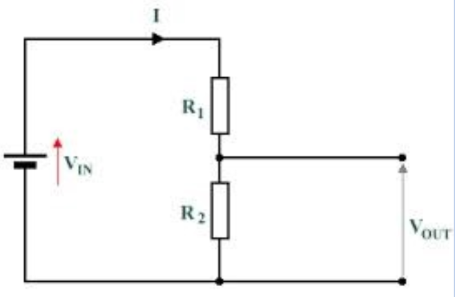
Potential divider equation
Vout = Vin × R2 / (R1 + R2)
Similaraty and difference between e.m.f. and p.d.
Both are measured in volts and are defined as the energy transferred per unit charge
Charges are losing energy for p.d. and gaining energy for e.m.f
Definition of the kilowatt hour
A unit of energy equal to the energy transferred by a 1kW device in a period of 1 hour.
Equals 3.6MJ
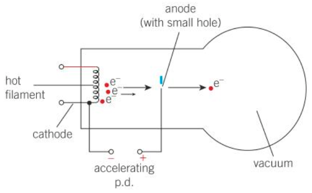
How an electron gun produces a beam of high speed electrons
Electrons are emitted from the hot wire/filament at the rear of the electron gun through thermionic emission
There is a large p.d. between the filament and an anode.
Electrons are accelerated towards the anode.
They pass through a hole in the anode, producing a beam of high speed electrons.
Equation relating work done on electrons and their gain in kinetic energy
eV = ½mv2
work done on electron = gain in KE
Explain what is meant by internal resistance
The resistance of a source of e.m.f (e.g. a cell) due to its construction, which causes a voltage drop across the battery when a current is drawn from it.
Define lost volts
The potential difference across the internal resistor of a source of e.m.f
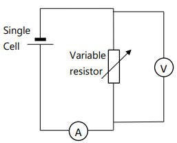
Finding Internal resistance practical (with circuit, equations, graph, safety)
Method:
Set up the circuit as shown in diagram.
Record the voltage across and current through the variable resistor in a table
Vary the resistance (by adjusting the variable resistor) and record the voltage across and current through the variable resistor each time.
Make sure to record at least 5 pairs of voltage and current readings across a decent range.
Analysis:
Plot a graph of V against I from the recorded values, drawing a line of best fit that extends all the way back to the y-axis to find the y-intercept. Then calculate the gradient of the line of best fit
Using Kirchhoff’s 2nd law, ε = IR + Ir. V = IR, so ε = V + Ir. Rearranging this gives V = -rI + ε
As such the gradient of our line of best fit = -r, so r = -1 × gradient, and the y-intercept = ε.
Safety:
Be careful handling the battery as it can be hot from the current
Do not set the variable resistor too close to zero resistance as this will cause the current to be larger. Too large of a current can cause the battery to overheat
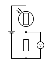
You are designing a circuit for a light meter to monitor changes in light intensity. The meter reading must rise when the light intensity increases. The incident light may cause the resistance of the LDR to vary between 1500 Ω and 250 Ω.
You can use either a 1500Ω or a 750Ω fixed resistor
You can use either a ammeter or a voltmeter
Draw a suitable circuit and explain why the reading on the meter increases with increasing light intensity and which of the two fixed resistors gives the largest scale change on the meter for the change in light intensity.
Circuit:
As shown in image if using voltmeter, otherwise ammeter should be in series with the two resistors
Action of circuit:
When light intensity increases the resistance of LDR falls
So p.d. across the fixed resistor increases (or current in circuit increases as total resistance is lower) so the meter reading increases
Meter and sensitivity:
Need the largest change in voltage or current for a given change in light intensity
Choose the resistor of 750Ω to give the largest change on the meter
Electronvolt
A unit of energy
1 eV is the energy transferred to or from an electron when it passes through a potential difference of 1 volt
1 eV is equivalent to 1.60 × 10⁻¹⁹J
Ohmic conductor
A conductor that obeys Ohm’s law
Define the Ohm
The resistance of a component that has a potential difference of 1V per unit ampere
The derived SI unit of resistance
Negative temperature coefficient (NTC)
A relationship in which a variable decreases as temperature increases
Example: the resistance of NTC thermistors
Explain why the increase in temperature of a wire causes its resistance to increase
As the metal ions are heated, their kinetic energy increases
This causes them to vibrate with greater amplitude about their mean positions
This increases the frequency of collisions between charge carriers and the positive metal ions, so the charge carriers do more work.
This means the p.d. (V) increases.
R∝V, so the resistance will also increase.
Factors that affect the resistance of a wire
Temperature
(Resistivity of) the material of the wire
Cross-sectional area
Length of component
The order of magnitude of reisistivity for a good conductor
10-8
The order of magnitude of reisistivity for a semi-conductor
Varying order between 10-8 and 1016
The order of magnitude of resistivity for an insulator
1016
The order of magnitude of number density for a good conductor
1028
The order of magnitude of number density for a semi-conductor
1017
The order of magnitude of number density for an insulator
109
Why is charge quantised?
Charge is quantised because it can only have certain values - integer multiples of the elementry charge
Equation linking charge and elementry charge
Q=ne
Net charge = number of electrons × elementry charge
Name the charge carriers responsible for electric current in metals
Electrons
What is the name of the charge carriers responsible for electric current in an electrolyte?
Ions
Define terminal p.d.
The p.d. across an electrical power source
When there is no current this is equal to the e.m.f of the source
When there is current this is equal to e.m.f. minus lost volts