Spectrophotometers (with emphasis on Spectrophotometers (L03; chptr 19)
1/38
Earn XP
Description and Tags
CHEM 310: Foundations of Analytical Chemistry
Name | Mastery | Learn | Test | Matching | Spaced | Call with Kai |
|---|
No study sessions yet.
39 Terms
Spectrophotometer
measures the light that passes through a sample, giving your readings in percent transmittance (%T) or in absorbance (A)
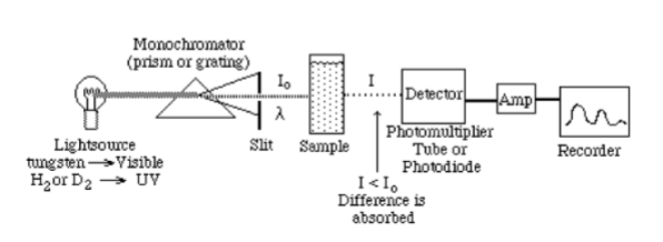
Basic Parts of a Spectrophotometer
light source - a stable and low cost energy source
monochromator - splits polychromatic radiation (light) into specific wavelengths
sample holder - “transparent” vessels (cuvettes) to hold your sample
detector - a photosensitive detector and associated amplifier and recorder
The process of light being absorbed by a solution
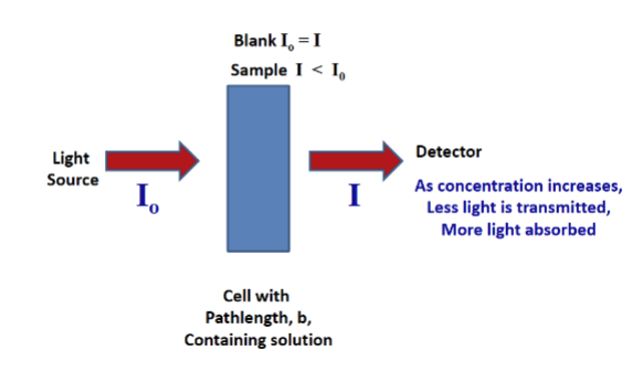
The Blank
contains all substances except the analyte
used to set the absorbance to zero, to zero the instrument
this is done by removing any absorption of light due to the other substances in solution + it removes the cell, thus ensuring that all of the measured absorbance is due to the analyte

Single Beam Spectrophotometer
inherent advantage of greater throughput
superior signal-to-noise ratio (S/N)
less clutter sample compartment
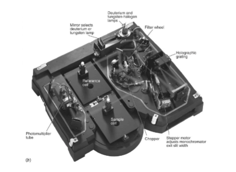
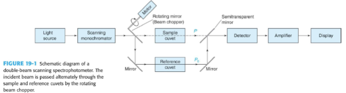
Dual Beam Spectrophotometer
light alternatively passes through the sample and the reference (the blank), directed by a chopper (a rotating mirror that directs the beam)
advantage is that is compensates for fluctuations in radiant output of source and drift in transducer and amplifier
most modern UV-vis recording instruments are double beam (at least in kinetic analysis)
Light sources on 3 different types of spectrophotometers:
UV Spectrophotometer
a. Hydrogen Gas Lamp (also deuterium)
b. Mercury Lamp
Visible Spectrophotometer
a. Tungsten Lamp
IR Spectrophotometer
a. Carborundum (SiC)
Light sources: the lamps of spectrophotometers (3)
Deuterium Arc Lamp
a. UV region; wavelength ranges from 190 - 420 nm
b. controlled electric discharge causes D2 to dissociate and emit UV radiation
Tungsten Lamp
a. part of the UV and the whole visible region; wavelength ranges from 350 - 2,500 nm
b. Tungsten filament is heated to 3000 K and produces radiation
Xenon Lamp
a. wavelength ranges from 190 - 800 nm
b. electric discharge arc lamp filled with Xe gas
What is the source of random error in every spectrophotometer instrument?
stray light reaching the detector
Stray light variable
= S% of P0
irradiance passing through the sample
P
Apparent transmittance
the real transmittance taking into account stray light that can be compared to true transmittance
= (P + S) / (P0 + S)
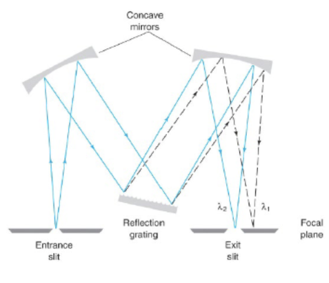
Monochromator
It accepts polychromatic input light from a lamp and outputs monochromatic light. It disperses light into its component wavelengths and selects a narrow band of wavelengths to pass to the sample or detector
Components of a monochromator
entrance slit
dispersion device
exit slit
resolving element (two kinds:)
a. prisms = simple glass prisms are used for vis range for UV region silica / fused silica or quartz prism is used
b. gratings = often used in the monochromators of spectrophotometers operating in UV, vis, and IR regions; its resolving power is far superior to prisms
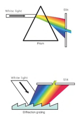

Grating
It’s a reflective optical component with a series of closely rules lines, called grooves, coated with aluminum to make it reflective and a thin layer of silica to protect the surface from oxidation. When light is reflected, each groove behaves as a source of radiation—in-phase light rays reinforce each other and out-of-phase light cancels out.
Filters
The simplest filter is colored glass which absorbs a broad portion of the spectrum and transmits other portions. Interference and holographic filters are constructed for finer control.
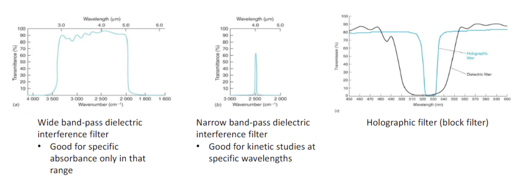
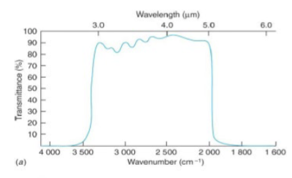
wide band-pass dielectric interference filter
good for specific absorbance only in that range
the interference filters, based on exploiting optical interference effects, selectively transmits constructively reinforced wavelengths and simultaneously eliminates unwanted light
has a quality factor Q of <10 (compare this to narrow band-pass dielectric interference)
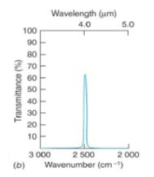
narrow band-pass dielectric interference
good for kinetic studies at specific wavelengths
the band-pass filters the passage of light to a narrow bandwidth/wavelength, reflecting/blocking all other light
has a quality factor Q of >10 ((compare this to wide band-pass dielectric interference filter)
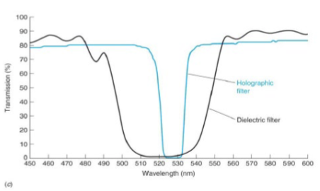
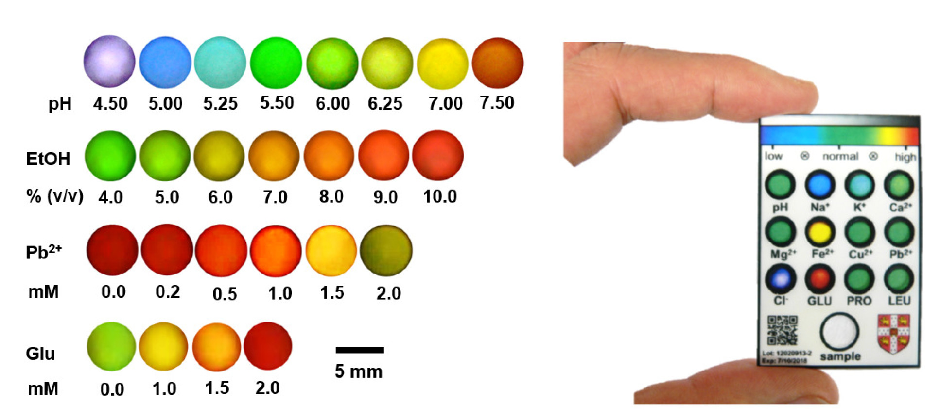
holographic filter
good for quantitative analysis of biomarkers
when the holographic sensor is lit with broadband white-light source, the grating produces visible-light diffraction and displays a monochromatic color, then it reports on the concentration of analytes by its Bragg diffraction peak changes
What type of cell do you use for a UV spectrophotometer?
Quartz (fused silica)
What type of cells do you use for visible spectrophotometers? (3)
quartz, glass, and plastic
What type of cells do you use for IR spectrophotometers
NaCl, KCl, and KBr (salt disks)
What types of solvents are not compatible with most salt plates?
Most salt plates (NaCl, KBr etc.) are made of salt and salts are highly soluble in water. Hence the sample preparation solvent as well as the cleaning/washing solvent must be anhydrous. Presence of water in the solvent will dissolve away the salt plate. Only dry organic solvents must be used. Water or wet solvents are not compatible with salt plates.
detection devices
most detectors depend on the photoelectric effect, where an incident photon liberates electrons from a metal or other material surface
What are the 5 important requirements of detection devices?
High sensitivity - to allow detection of low levels of radiant energy
Great quantum efficiency
Short response time
Long term stability
An electronic signal, which is easily amplified for typical readout
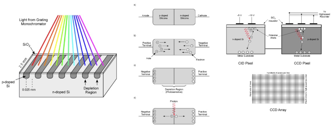
Charged Coupled Device (CCD), a detection device
This device is made from p-doped Si on an n-doped substrate. When light is absorbed at the p-doped region, an electron is introduced to the conduction band and a hole is left in the valence band. Electrons are attached to the back of the positive electrode where it is stored; the holes migrate to the n-doped substrate where it combines with an electron.
Electrons are stored in each pixel, and they’re moved into a serial register so the charge can be read out. Each electrode stores ~105 electrons.
Charge-Coupled Device (CCD), a detection device (simply explained)
This is based on the photoelectric effect. When a photon hits a silicon sensor, it produces an electron. the capacitor attached to one side of the silicon sensor will collect the electrons produced by the photons, then the voltage across the capacitor will represent the number of electrons that were collected from the capacitor—this information will be sent to the computer.
photoelectric effect
where an incident photon liberates electrons from a metal or other material surface
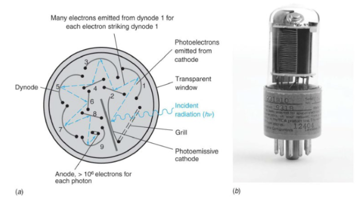
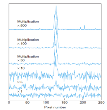
Photomultiplier Tubes (PMT), a detection device
It has a photosensitive cathode that emits electrons when struck by a photon. Electrons from the cathode are accelerated by a positive potential moving toward the first dynode, and when accelerated electrons hit the dynode, more electrons are emitted. This multiplication process continues until ~106 electrons are finally collected at the anode for each photon striking the photocathode. The signal is the current measured at the anode.

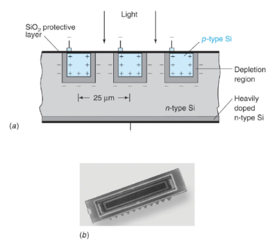
Photodiode Array (PDA), a detection device
There’s a linear array of p-type Si on an n-type Si substrate where the reverse bias draws electrons and holes away from the junction. The junction acts as a capacitor, with charge on either side of the depletion region. Electrons and holes are created when radiation is absorbed by the semiconductor, then the electrons and holes migrate to regions of opposite charge, which partially discharges the capacitor. The charge left in each capacitor is measured by measuring the current needed to recharge the capacitor.
IR Detector, a detection device
Infrared (IR) detectors work by sensing infrared radiation, which is emitted by objects based on their temperature. They typically use materials that change their electrical properties in response to IR radiation.
Types of Detectors:
Thermal Detectors: Measure temperature changes (e.g., thermocouples, bolometers).
Photon Detectors: Detect individual photons (e.g., photodiodes, phototransistors).
Operation:
When IR radiation hits the detector, it causes a change in resistance or generates charge carriers, which can be measured as an electrical signal.
Applications: Used in night vision, thermal imaging, and motion detection systems.
IR Detector: Thermal Transducers
Thermocouple—a junction between two pieces of dissimilar metals (i.e. Bi-Sb). A potential develops between the two junctions that varies with the difference in temperature to move charge.
IR Detector: Photoconducting Transducers
Semiconductor material (i.e. PbS) whose conductivity increased when IR radiation excites the electrons from the valence band to the conduction band
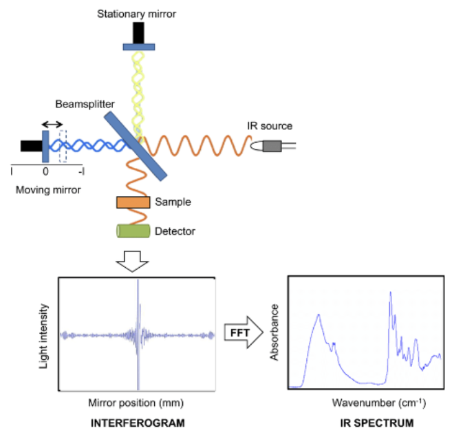
Fourier Transform IR (FTIR) Spectroscopy
This type of spectroscopy was developed to overcome limitations of dispersive instruments. It measures all infrared frequencies simultaneously and utilizes an interferometer device that produces all IR frequencies encoded into it. The signal can be measured very quickly in the order of seconds.
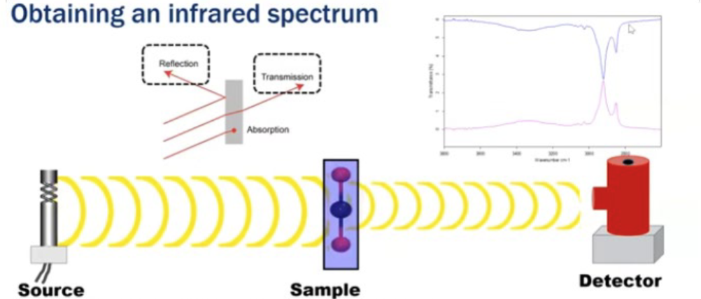
How do you obtain an infrared spectrum?
The bond vibrations give rise to absorption bands which impart a unique spectral fingerprint to each molecule. Anything that can affect that bond will affect the IR peak associated with it.

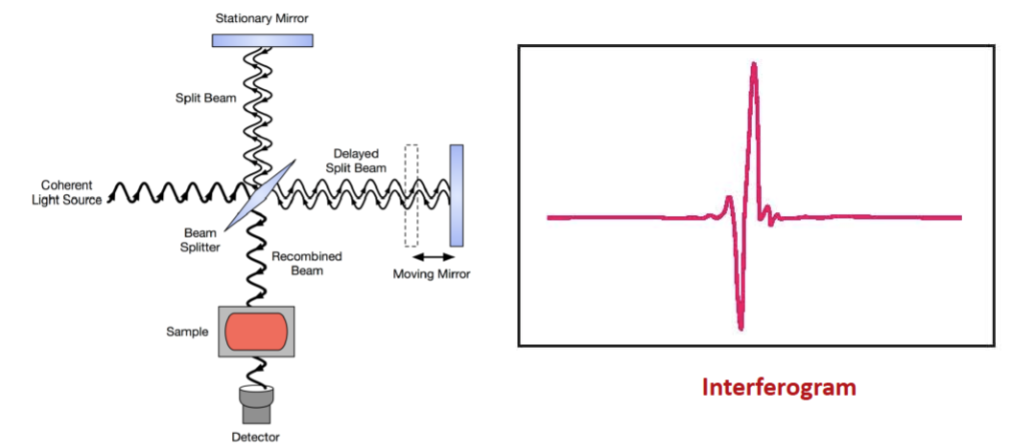
Michelson Interferometer
It splits a beam of radiation into two beams of nearly equal power and then recombines them in such a way that intensity variations of the combined beam can be measured as a function of the differences in the lengths of the paths of the two beams. The signal obtained will represent the spectrum of the source minus the spectrum of the sample.
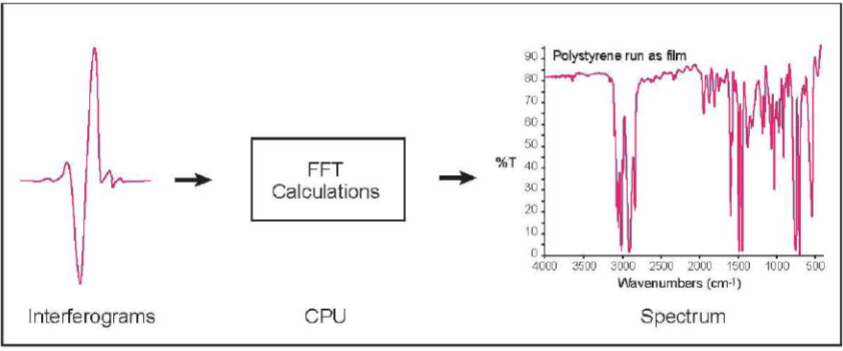
Fourier Transform (FFT) of a Signal
Mathematical operations are done to convert frequency space and obtain back the intensities at the component wavelengths
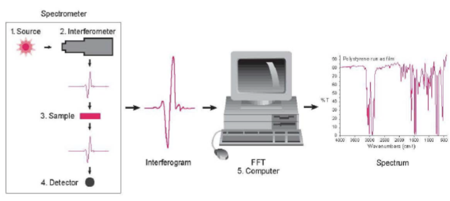
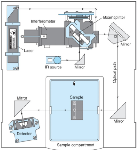
Components of a FTIR Spectrophotometer
Source - Infrared energy is emitted from a glowing black-body source. This beam passes through an aperture which controls the amount of energy presented to the sample.
Interferometer - The beam enters the interferometer where the “spectral encoding” takes place. The resulting signal then exits.
Sample - The beam enters the sample compartment where it is transmitted through or reflected off the surface of the sample. This is where specific frequencies of energy, which are uniquely characteristic of the sample, are absorbed.
Detector - It’s designed to measure the special interferogram signal.
Computer - The measured signal is digitized and sent to the computer where the Fourier transformation takes place. The final IR interpretion and any further manipulation may also take place.
What’s so great about FTIR Spectroscopy?
It provides a precise measurement without external calibration, and it enjoys increased speed, increased sensitivity (one second scans can be averages together to ratio out random noise), greater optical throughput, and it’s mechanically simple without any moving parts!
