Gleim Unit 3 - Airports, Air Traffic Control, and Airspace
1/85
There's no tags or description
Looks like no tags are added yet.
Name | Mastery | Learn | Test | Matching | Spaced | Call with Kai |
|---|
No analytics yet
Send a link to your students to track their progress
86 Terms
Visual Runway
Used for visual flight rules (VFR) operations. Markings include designation marking, centerline marking, and optional markings.

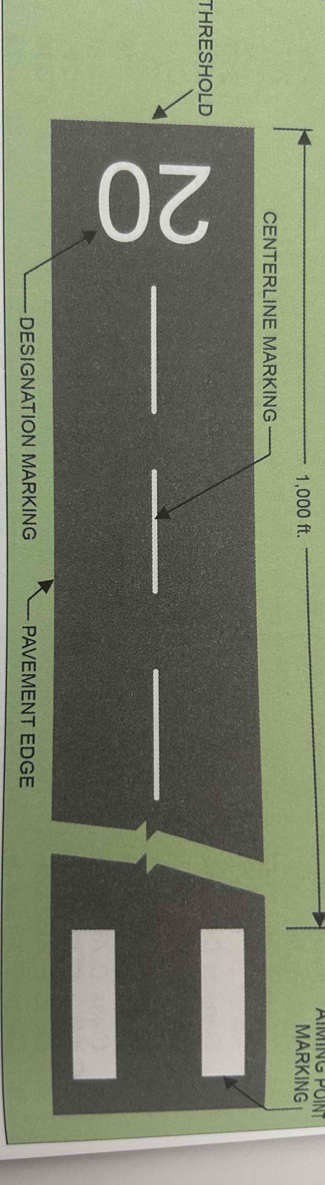
Designation Marking
Runway numbers and letters are determined from the approach direction. The runway number is the whole number nearest one-tenth the magnetic direction of the runway (e.g., a runway with magnetic direction of 200 degrees would be designated as runway 20) Letters differentiate between left (L), right (R), or center (C) parallel runways.

Centerline Marking
A dashed line that identifies the center of the runway and provides alignment guidance during takeoff and landing.
Optional markings
if runway is used or intended to be used by international commercial transport, threshold markings are required
If runway is 4,000 ft. or longer and is used by jet aircraft, an aiming point marking is required
runway side stripes may be added if necessary
Non-precision instrument runway
Served by a nonprecision instrument approach (i.e., no electronic glide slope), having markings of: designation, centerline, threshold, and aiming point.

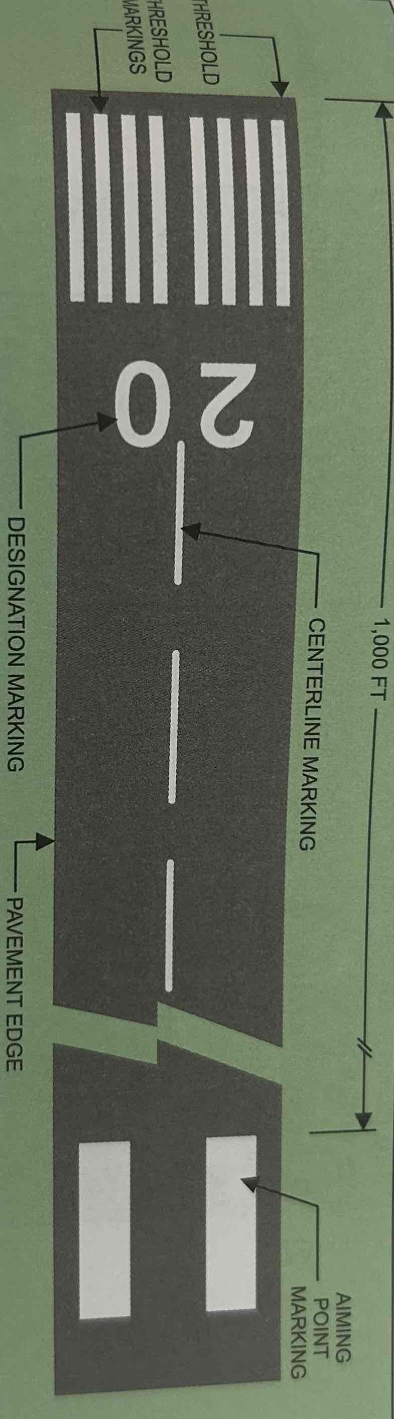
Threshold markings
Markings that help you identify the beginning of the runway that is available for landing. Come in two configurations: eight Longitundial stripes (four on each side of the centerline), and the number of stripes designated according to the width of the runway

Aiming Point Marker
Serves as visual aiming point during landing. Markings are two broad white stripes located on each side of the runway centerline approximately 1,000 ft. from the landing threshold.

Precision instrument runway
Served by a precision instrument approach, e.g., an instrument landing system (ILS). Markings include: all required for nonprecision instrument runway, touchdown zone markers, runway side stripe markings, and runway shoulder markings.
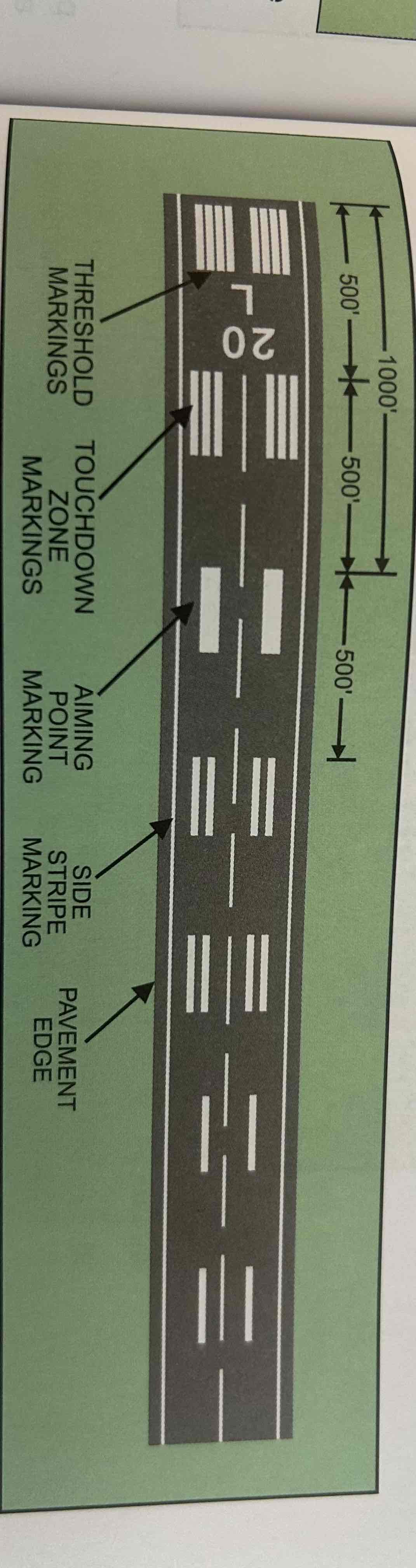
Runway side stripe markings
Continuous white stripes located on each side of the runway to provide a visual contrast between the runway and the abutting terrain or shoulders

Runway shoulder markings
Yellow markings and may not be used to supplement runway side stripes to identify the runway shoulder area that is not intended for use by aircraft
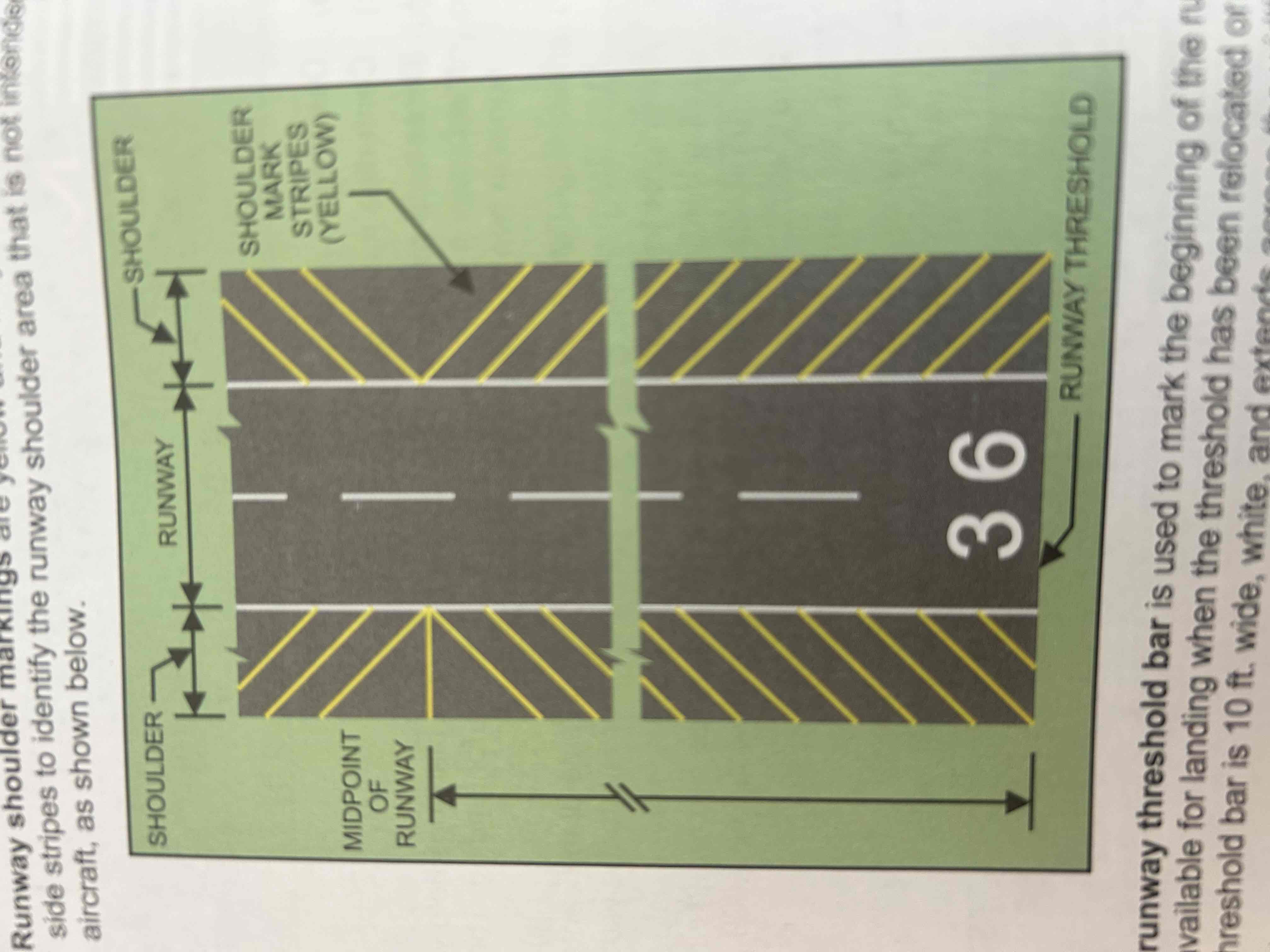
Runway threshold bar
Used to mark the beginning of the runway that is available for landing when the threshold has been relocated or displaced. The threshold bar is 10 ft wide, white, and extends across the width of the runway.
Relocated Threshold
Threshold that is temporarily relocated (due to construction, maintenance, etc) toward the departure end of the runway
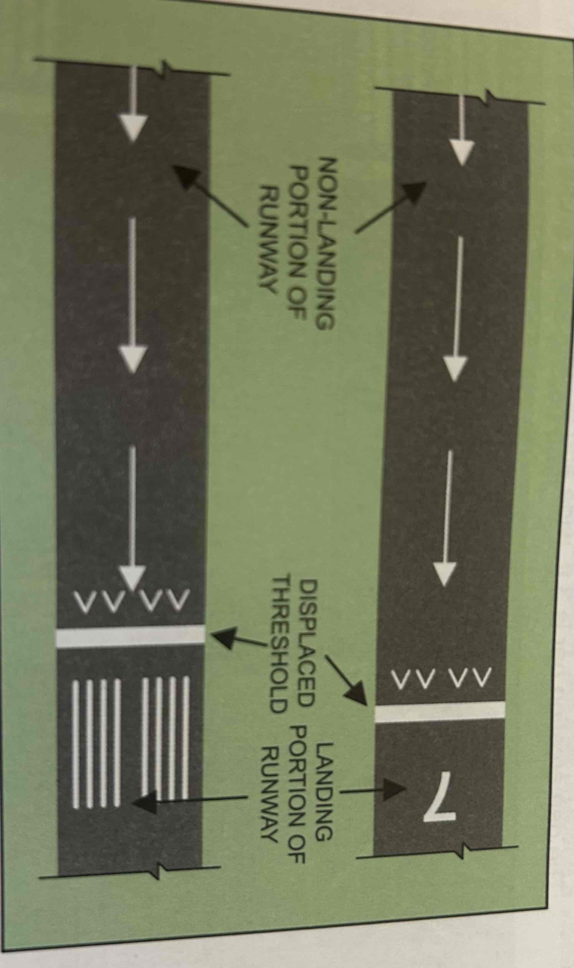
Displaced threshold
Threshold that is not at the beginning of the paved runway
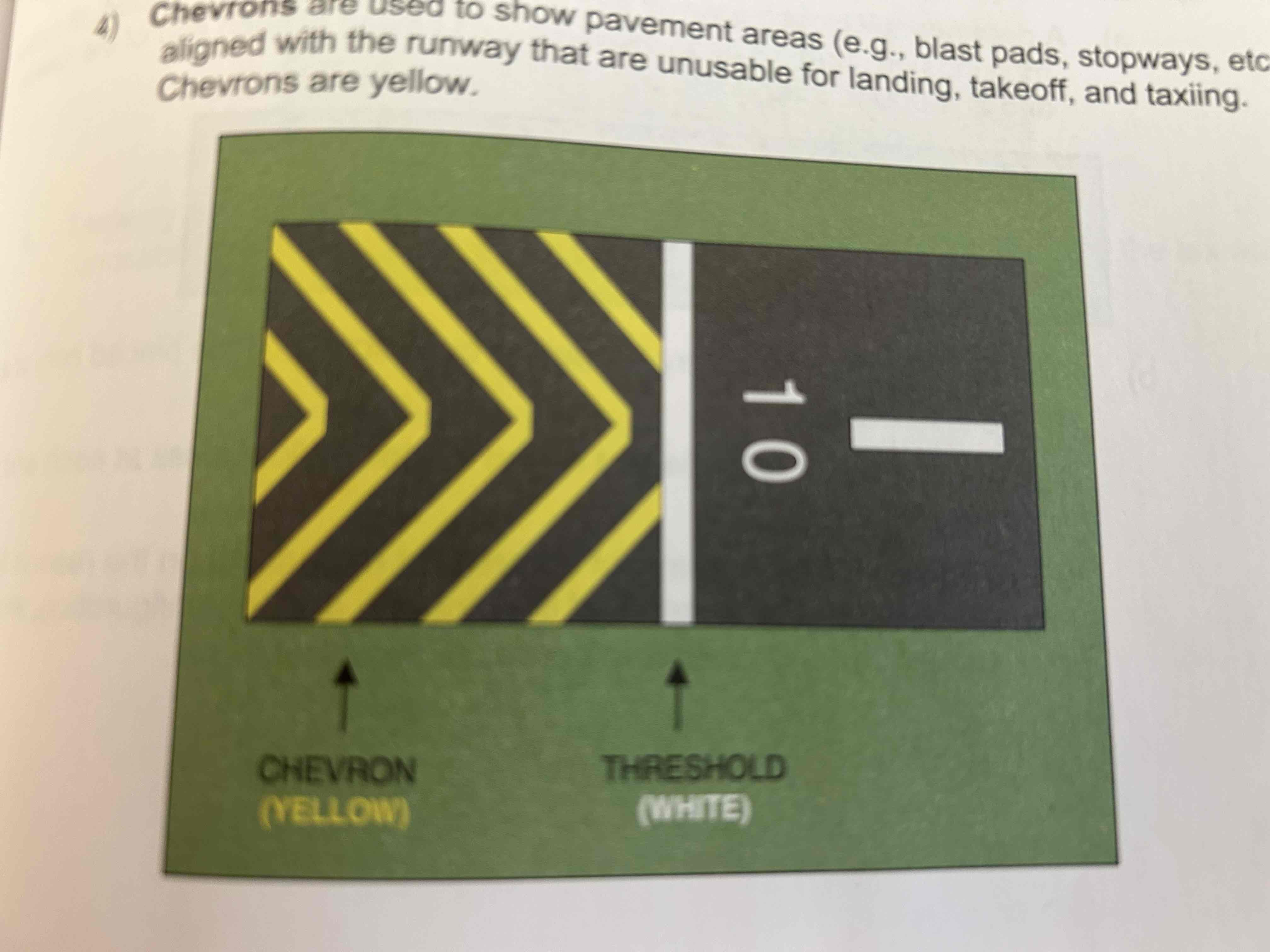
Chevrons
Yellow markings used to show pavement areas (e.g., blast pads, stopways, etc.) aligned with the runway that are unusable for landing, takeoff, and taxiing.
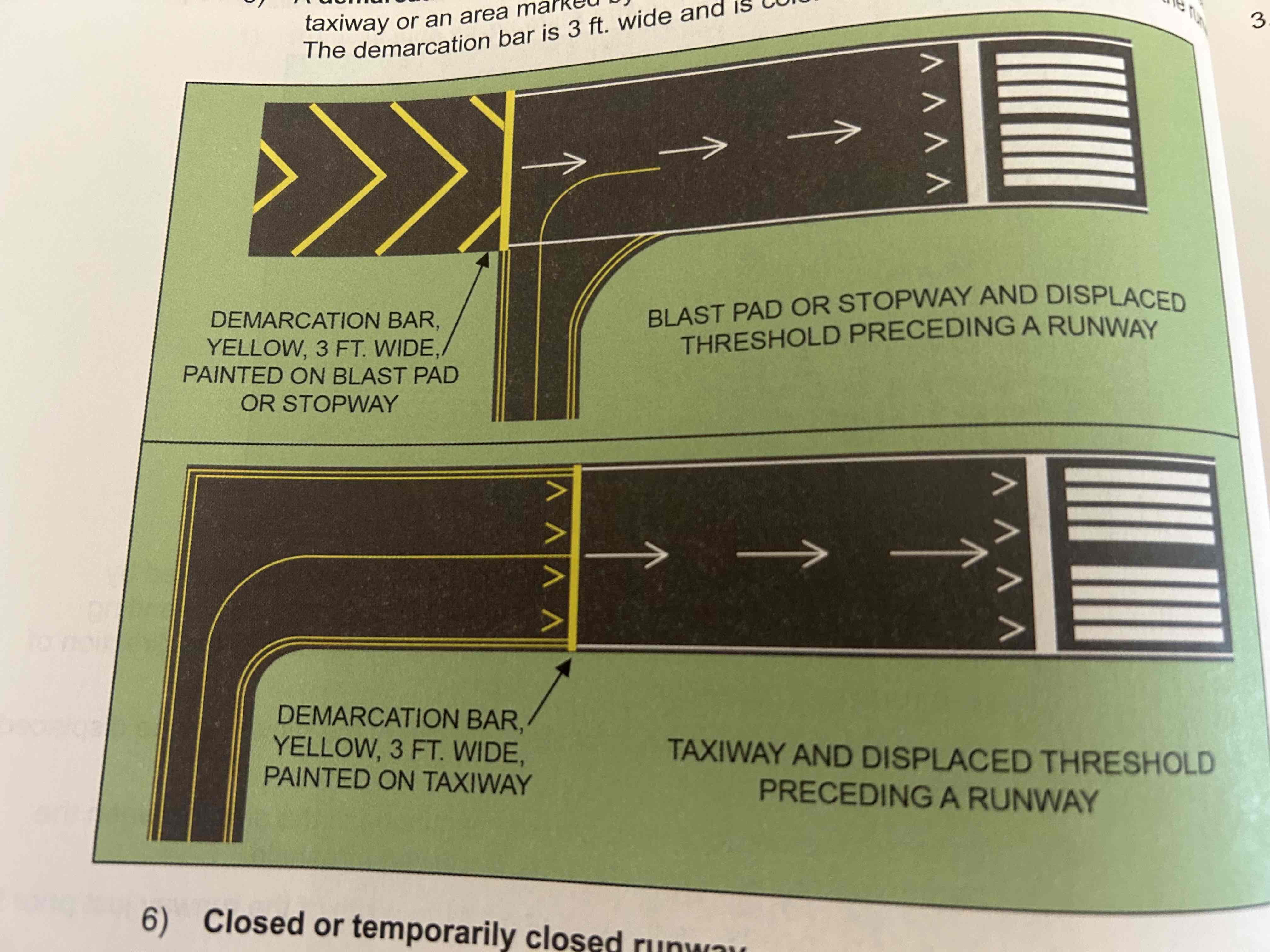
Demarcation bar
Separates a runway that had a displaced threshold from a taxiway or an area by chevrons that proceeded the runway. Markings are 3ft wide and colored yellow since they are not on the runway.
Closed/Temporarily closed runway
Has all runway lighting disconnected, all runway markings obliterated, and yellow crosses placed at each end of the runway and at 1000 ft intervals

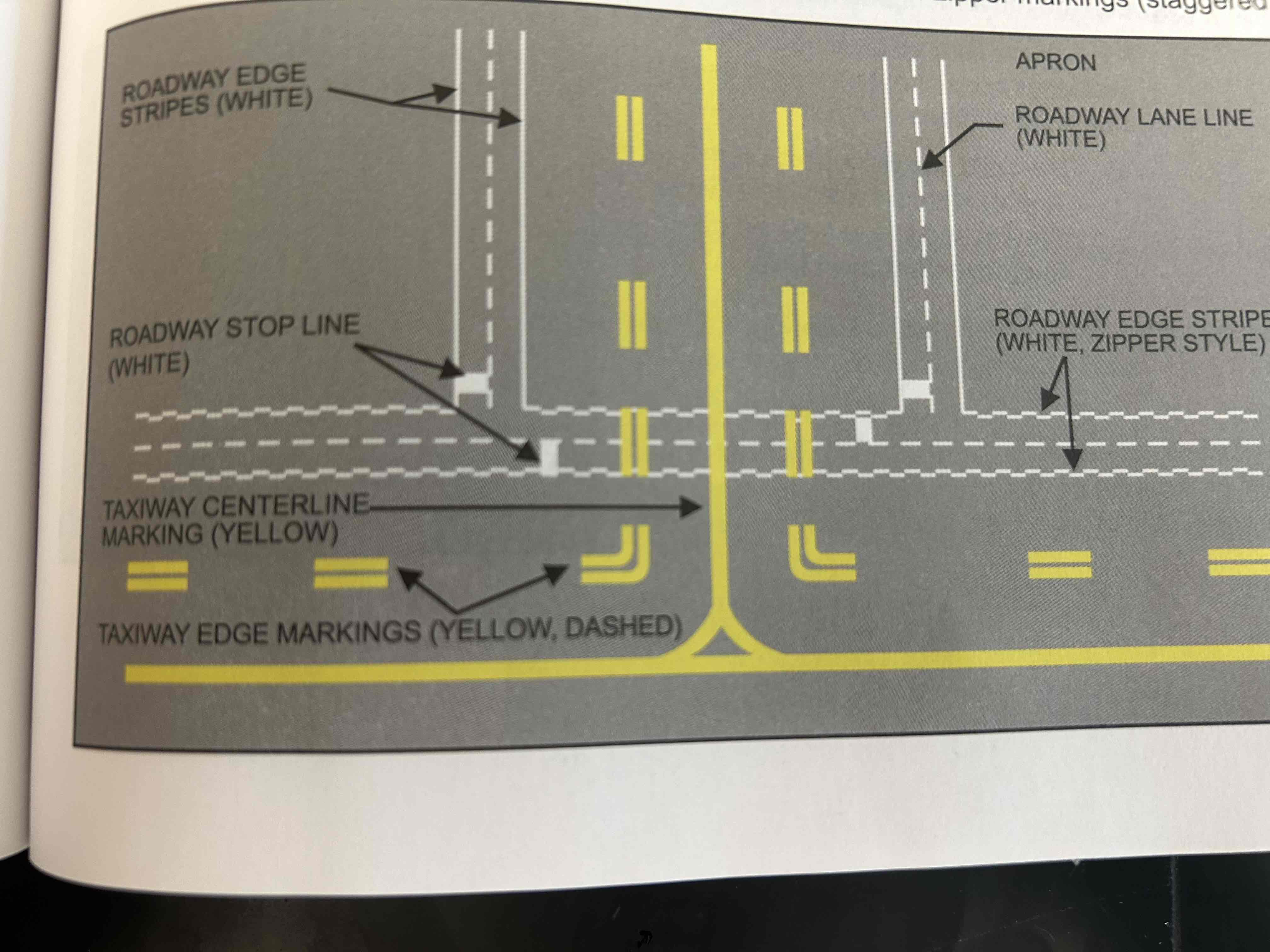
Taxiway Centerline
Single continuous yellow line that provides a visual cue to permit taxiing along a designated path
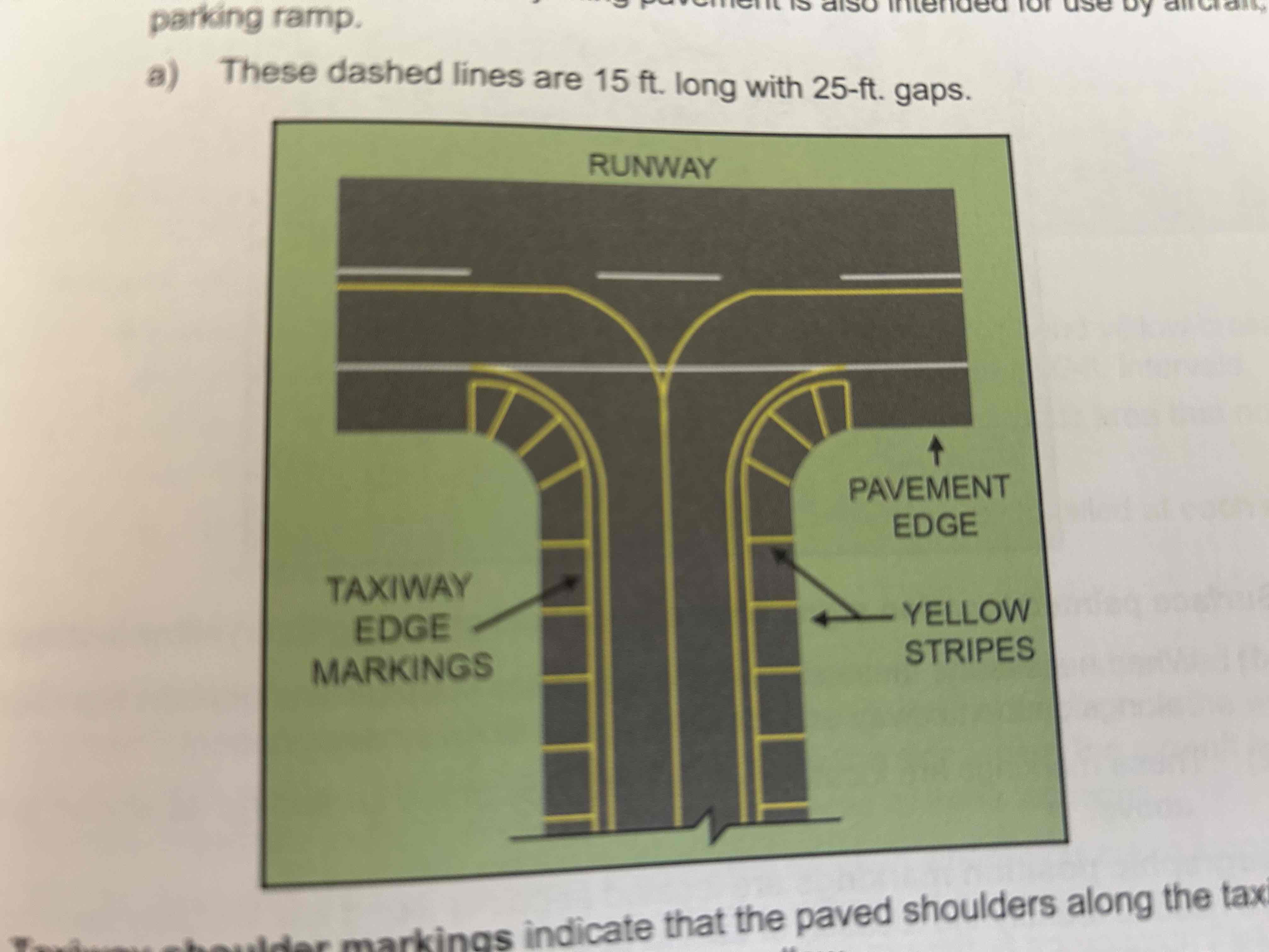
Taxiway edge markings
Primarily used to define the edge of the taxiway when the taxiway edge does not correspond with the edge of the pavement. There are two types, depending on wether your airplane is permitted to cross the taxiway edge.
Taxiway shoulder markings
Indicate that the paved shoulders along the taxiway are unusable. Marking are yellow
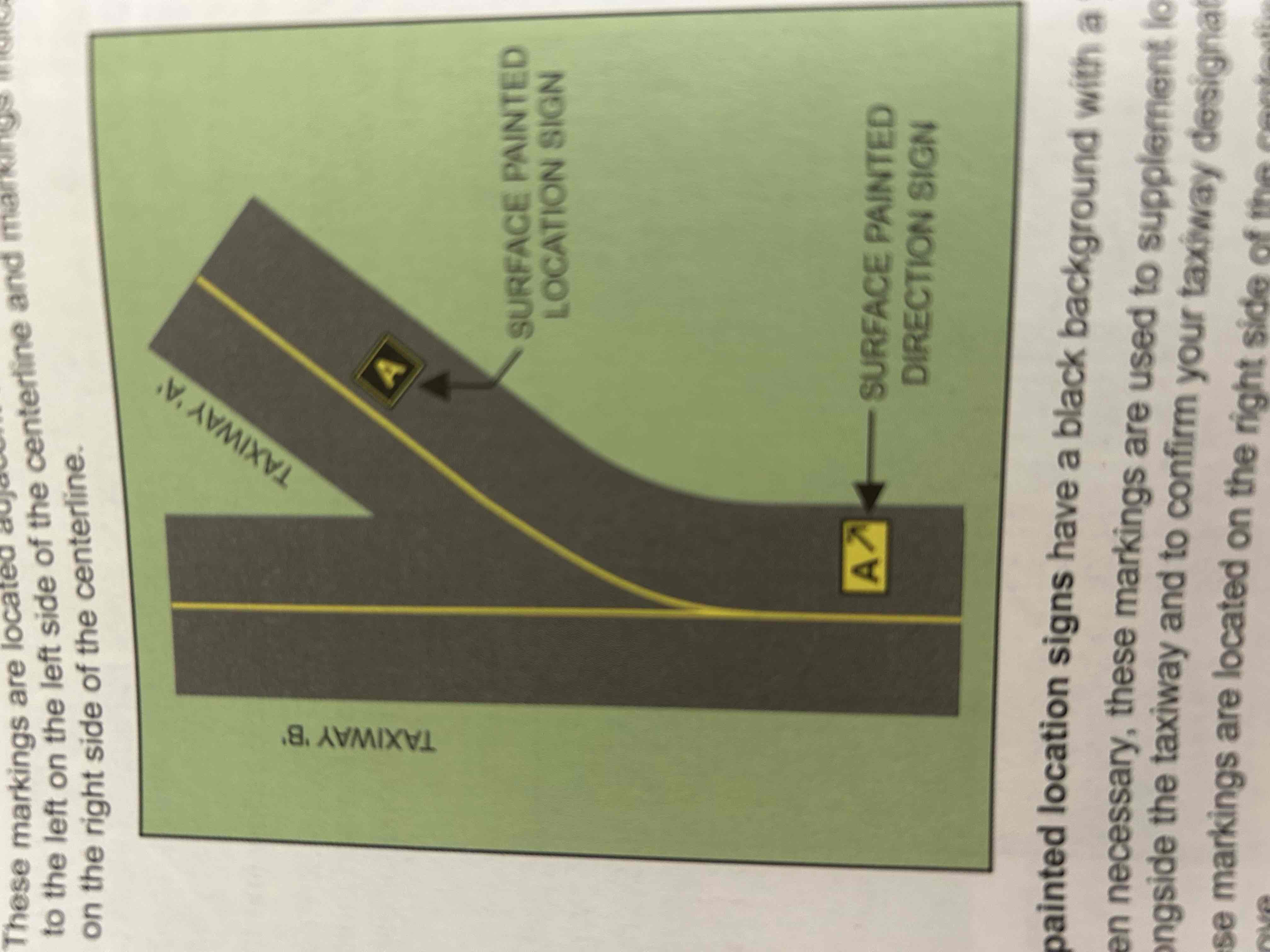
Surface painted taxiway direction signs
Yellow background with a black inscription and are provided when it is not possible to provide taxiway direction signs at intersections or when it is necessary to supplement such signs

Surface painted location signs
Black background with a yellow inscription, used to supplement location signs located alongside the taxiway and to confirm your taxiway designation
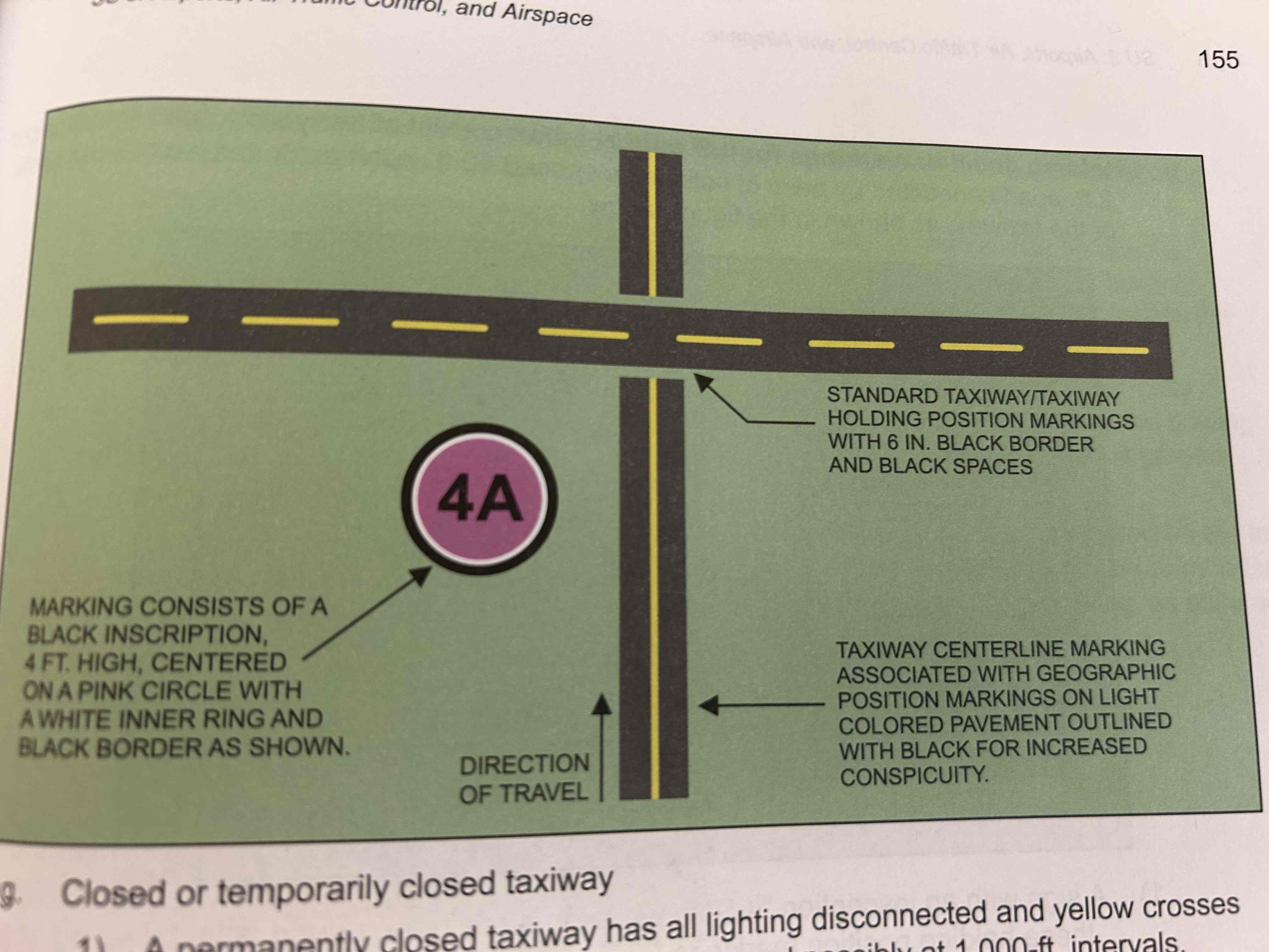
Geographic position markings
Located at points along low visibility taxi routes and are used to identify the location of taxiing aircraft during low visibility operations (i.e., when the runway visual range is below 1.200 ft.)
Runway holding position markings
Indicate where an aircraft is supposed to stop. They consist of four yellow lines, two solid and two dashed, extending across the width of the taxiway or runway. The solid lines are always on the side where the aircraft is to hold. Encountered at three locations: taxiways, runways, and approach/departure area of a runway.
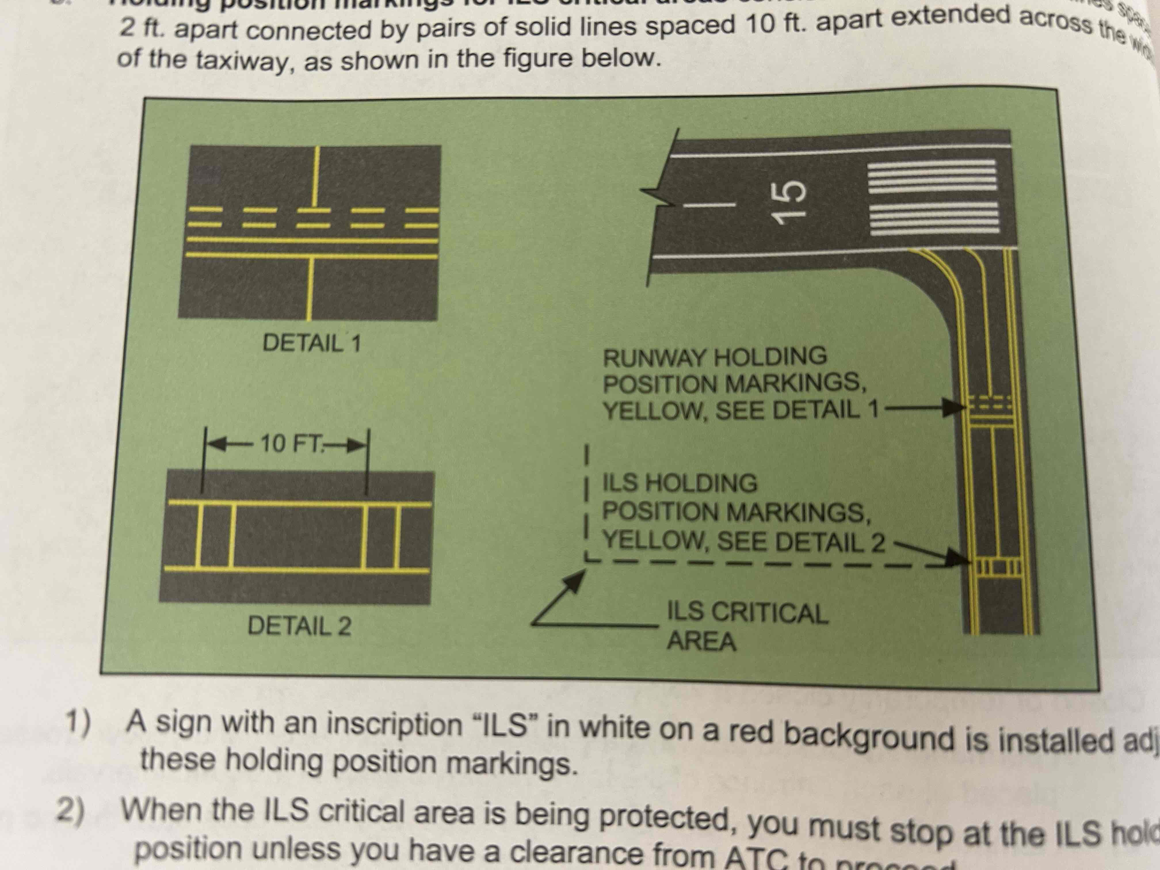
Holding position markings for ILS critical areas
Consist of two yellow solid lines spaced 2 ft. apart connected by pairs of solid lines spaced 10 ft. apart extended across the width of the taxiway
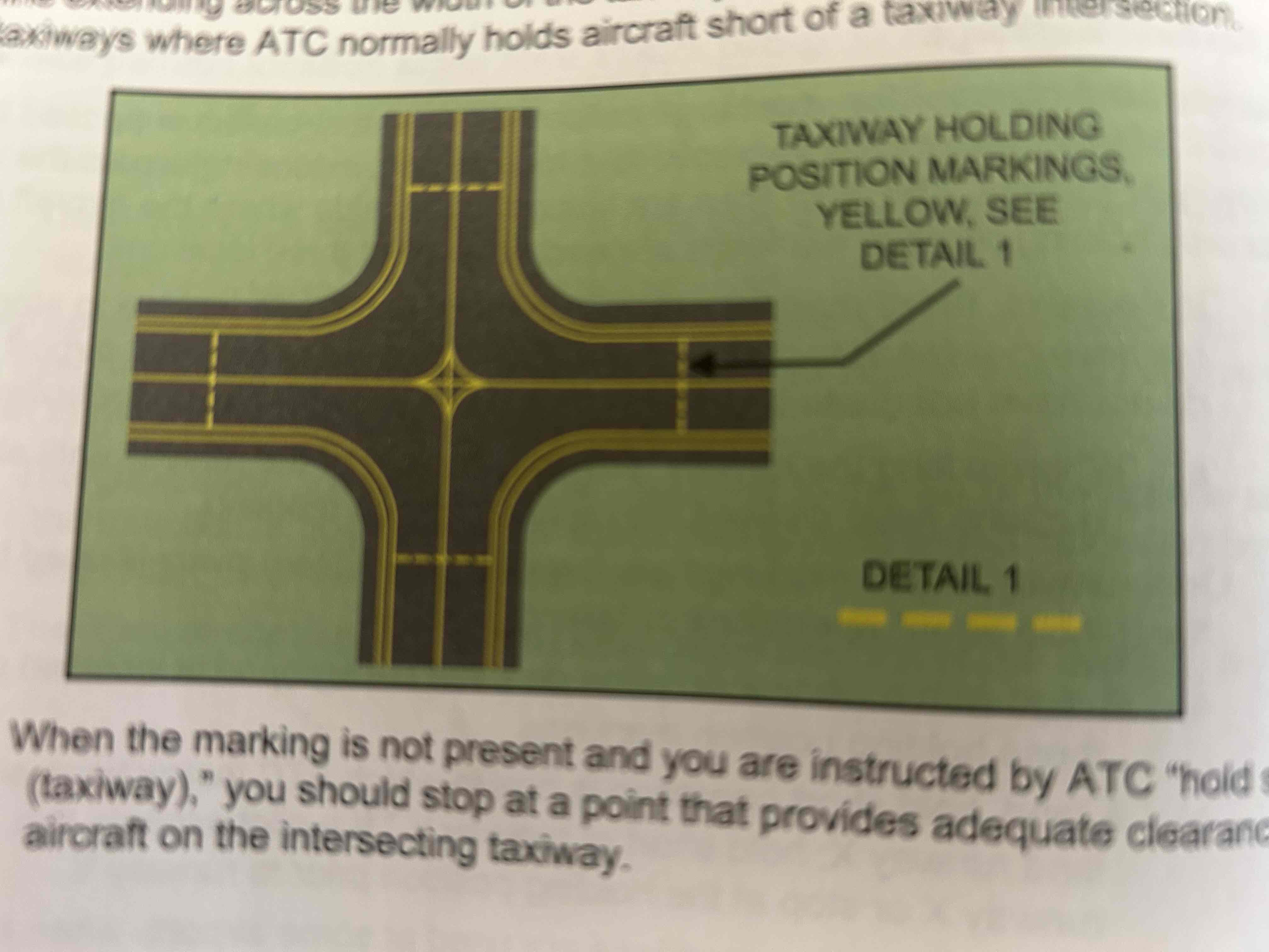
Holding position markings for taxiway/taxiway intersections
Consist of one dashed line extending across the width of the taxiway. Installed on taxiways where ATC normally holds aircraft short of a taxiway intersection.
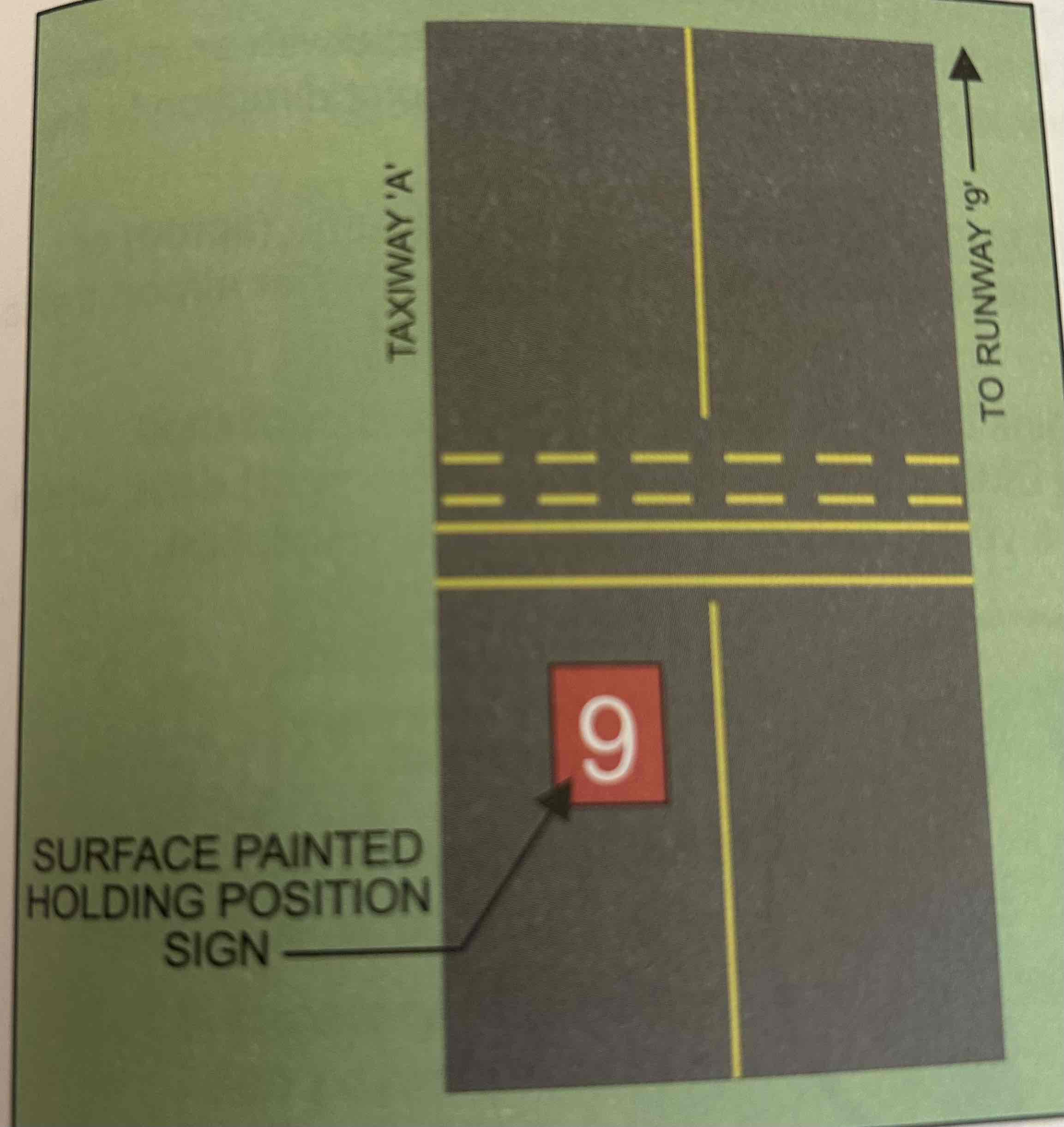
Surface painted holding signs
Red background with the intersecting runway’s designation in white. May be used to supplement runway holding position signs located alongside the taxiway.
Vehicle Roadway Markings
Used to define a pathway for vehicle operations or crossing areas that are also intended for aircraft.
VOR receiver checkpoint marking
Allows you to locate the position on the airport to preform a ground check of the VOR (VHF omnidirectional range) navigation instrument in your airplane, if equipped.
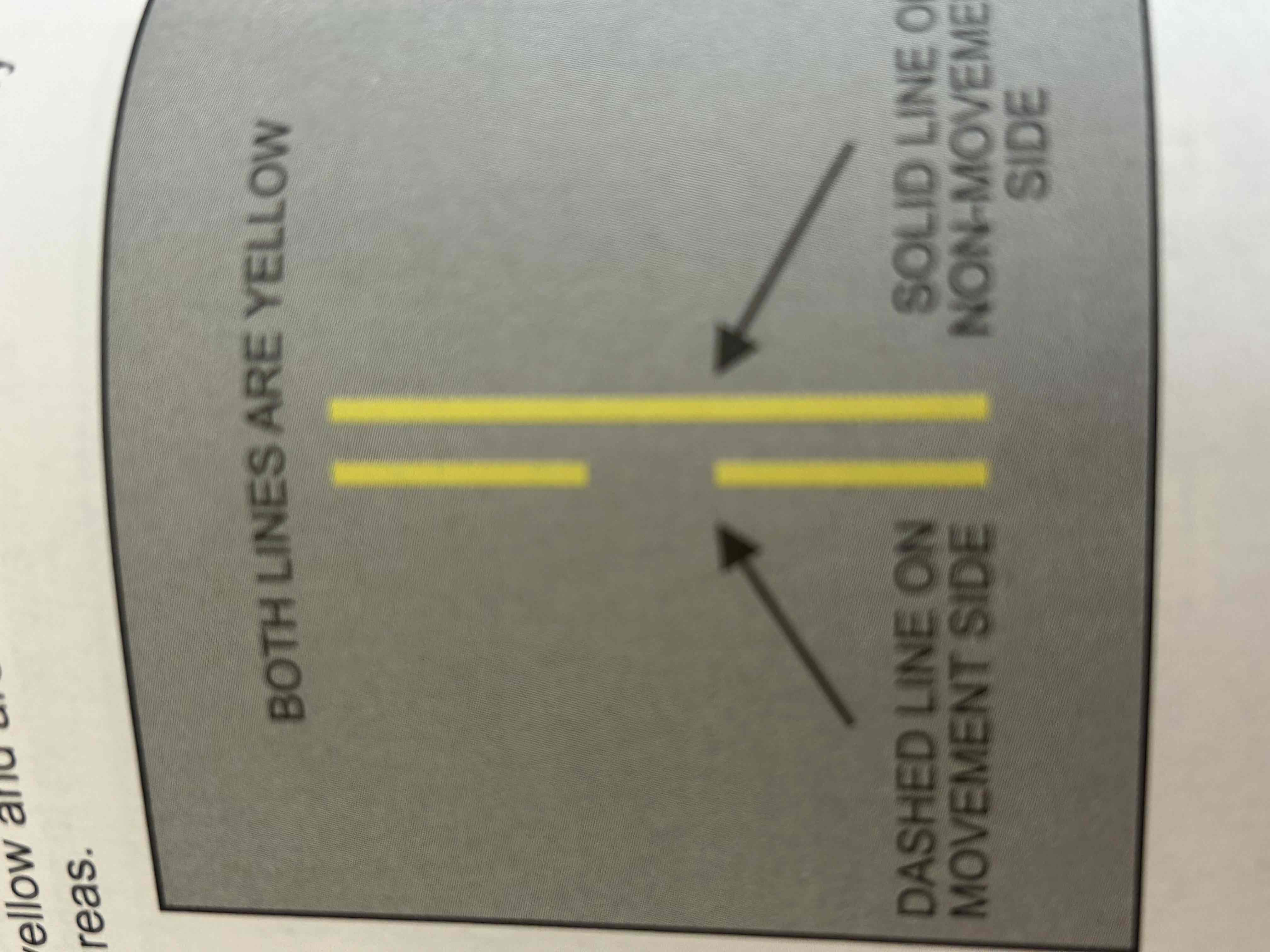
Non-movement area boundary markings
Delineate the movement area, i.e., the area under air traffic control. These markings are yellow and are located on the boundary between the movement and non-movement areas
Helicopter landing area markings
Used to identify the landing and takeoff areas at public-use heliports and hospital heliports.

Mandatory instruction signs
White characters on a red background and are used to denote entrances to runways or critical areas and areas that airplanes are prohibited from entering.
Runway holding position sign
Located at the holding position on taxiways that intersect a runway or on runways that intersect other runways
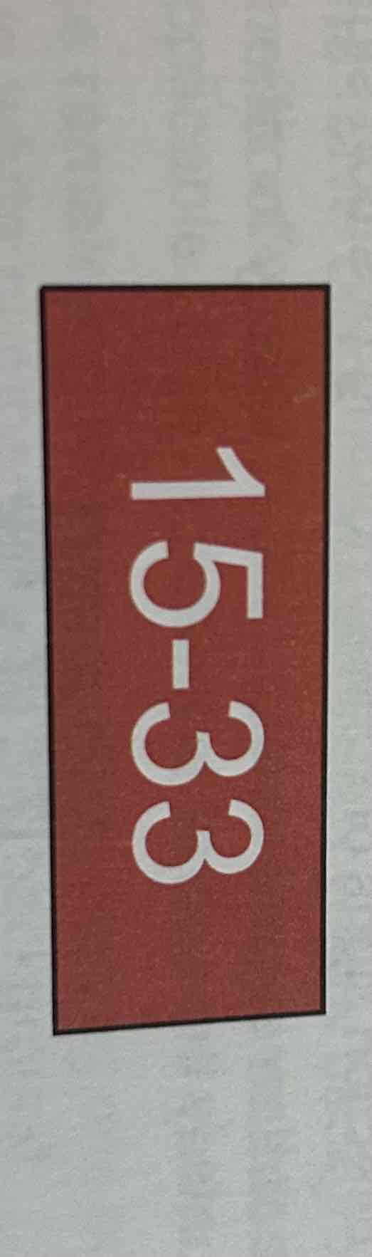
Runway approach area holding position sign
At some airports it is necessary to hold an aircraft on a taxiway located in the approach or departure area for a runway so that the aircraft does not interfere with operations on that runway. In the figure below, sign may protect the approach to runway 15 and/or the departure for runway 33.

ILS Critical area holding position sign
at some airports, when the instrument landing system (ILS) is being used, it is necessary to hold an aircraft on a taxiway at a location other than the marked runway holding position.

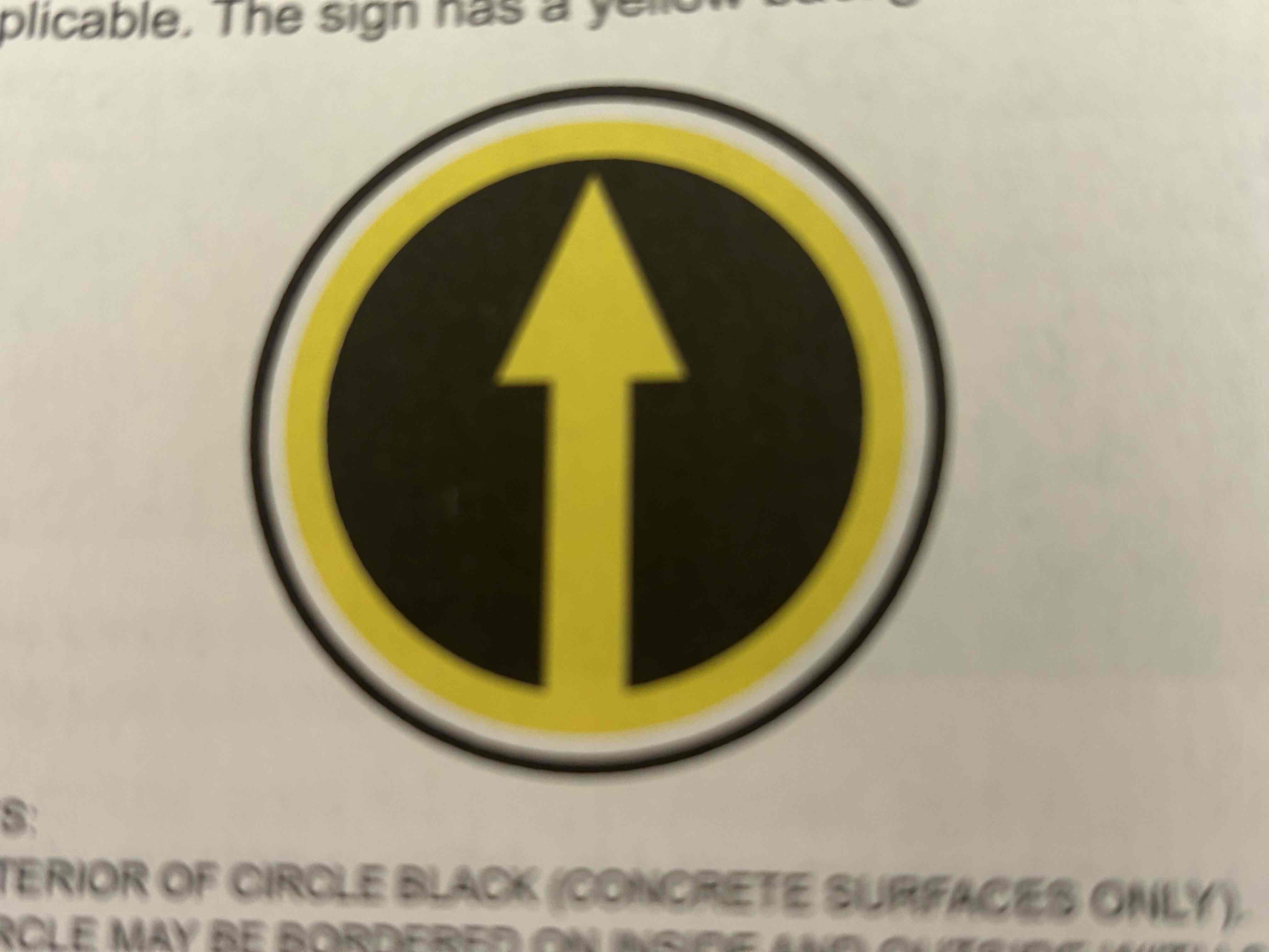
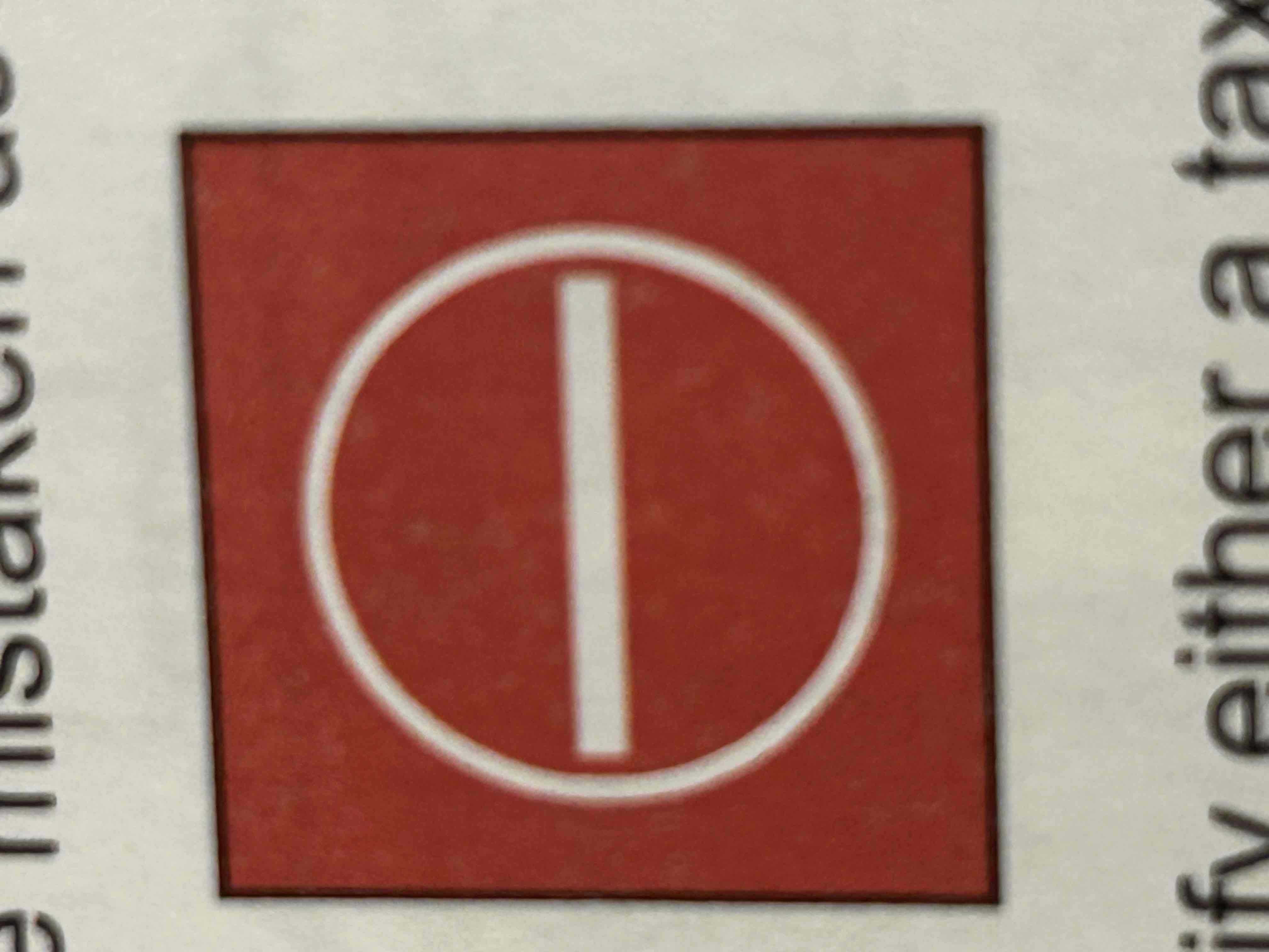
No entry sign
Prohibits an aircraft from entering an area. This sign would normally be located on a taxiway intended to be used in only one direction, at an intersection of a vehicle roadway with a runway or taxi, or at a location where the roadway may be mistaken as a taxiway or other aircraft movement sign.
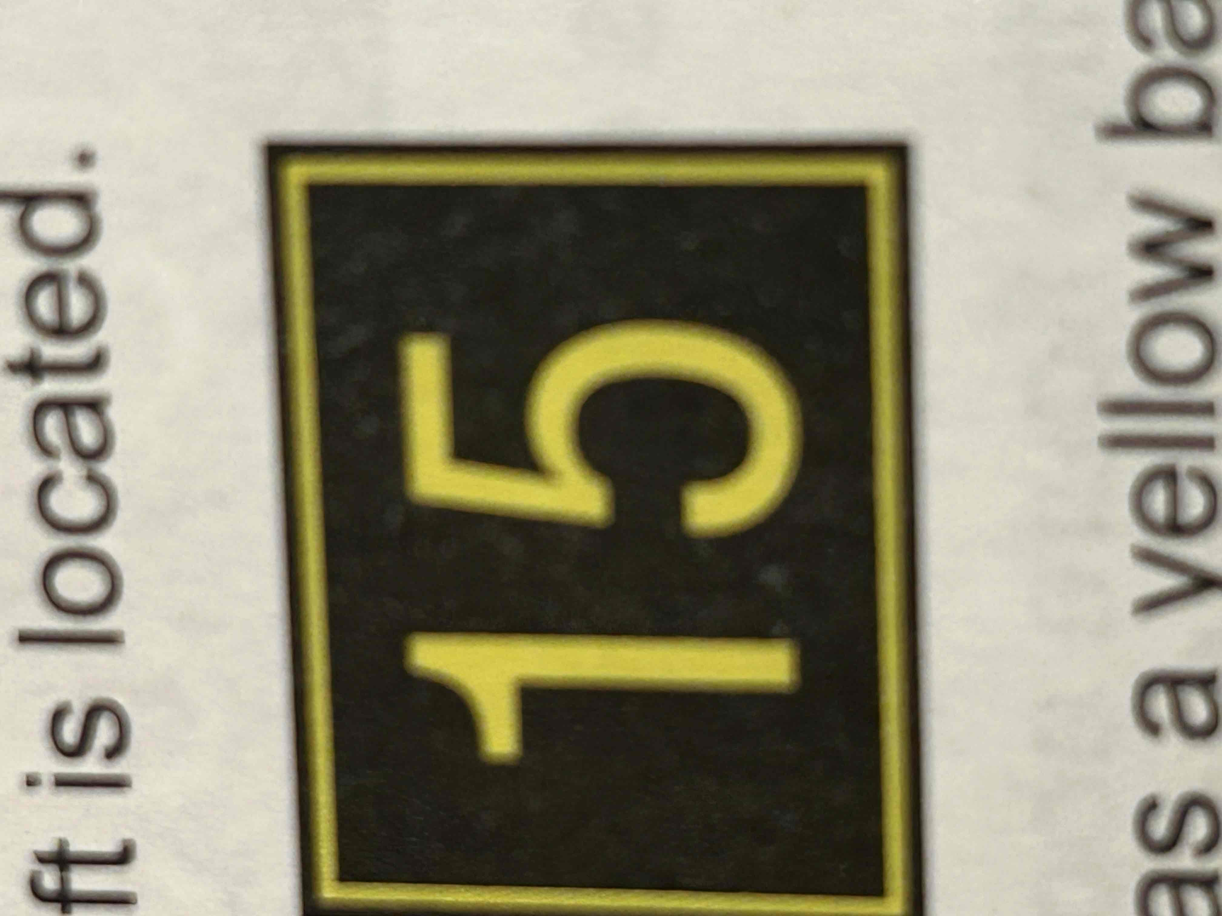
Taxiway Location Sign
Yellow characters on a black background and a yellow border. Used to identify taxiway or a runway on which the aircraft is located.

Runway location sign
Yellow characters on a black background and yellow border. It will indicate on which runway the the aircraft is located
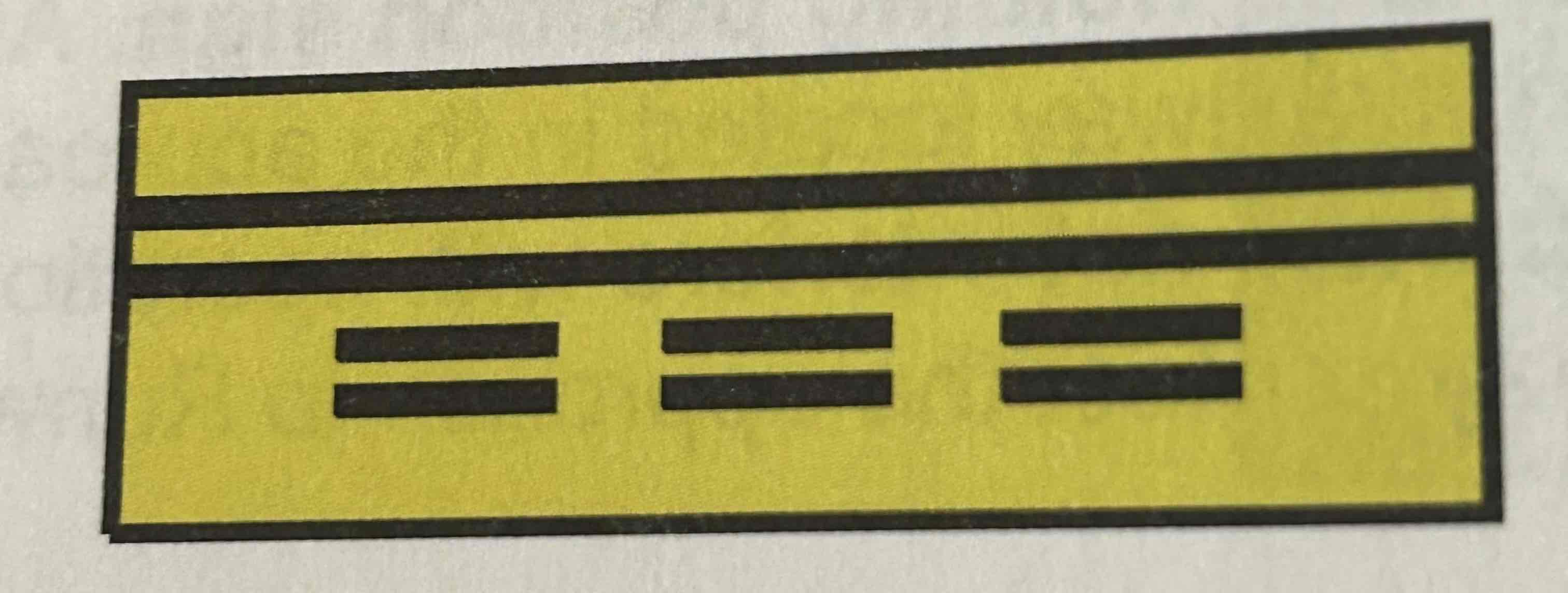
Runway boundary sign
Yellow background with a black inscription and a graphic depicting the pavement holding position marking.
ILS critical area boundary sign
Graphic depicting the ILS pavement holding position marking. Black on yellow background
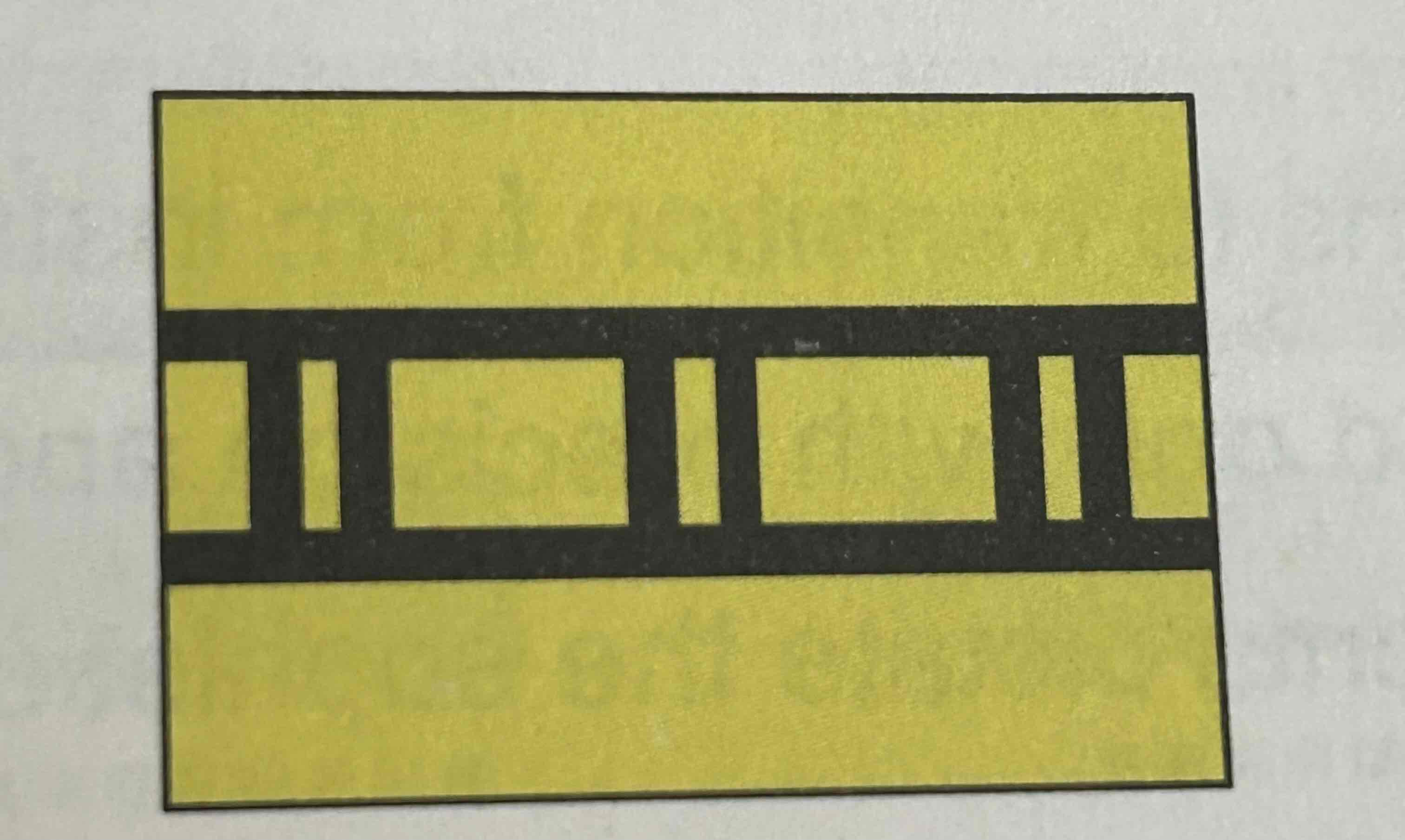
Direction Signs
Black characters on a yellow background. Inscription identifies the designation of the intersecting taxiways leading out of the intersection that a pilot would normally be expected to turn onto or hold short of. Each designation is accompanied by an arrow indicating the direction of the turn.
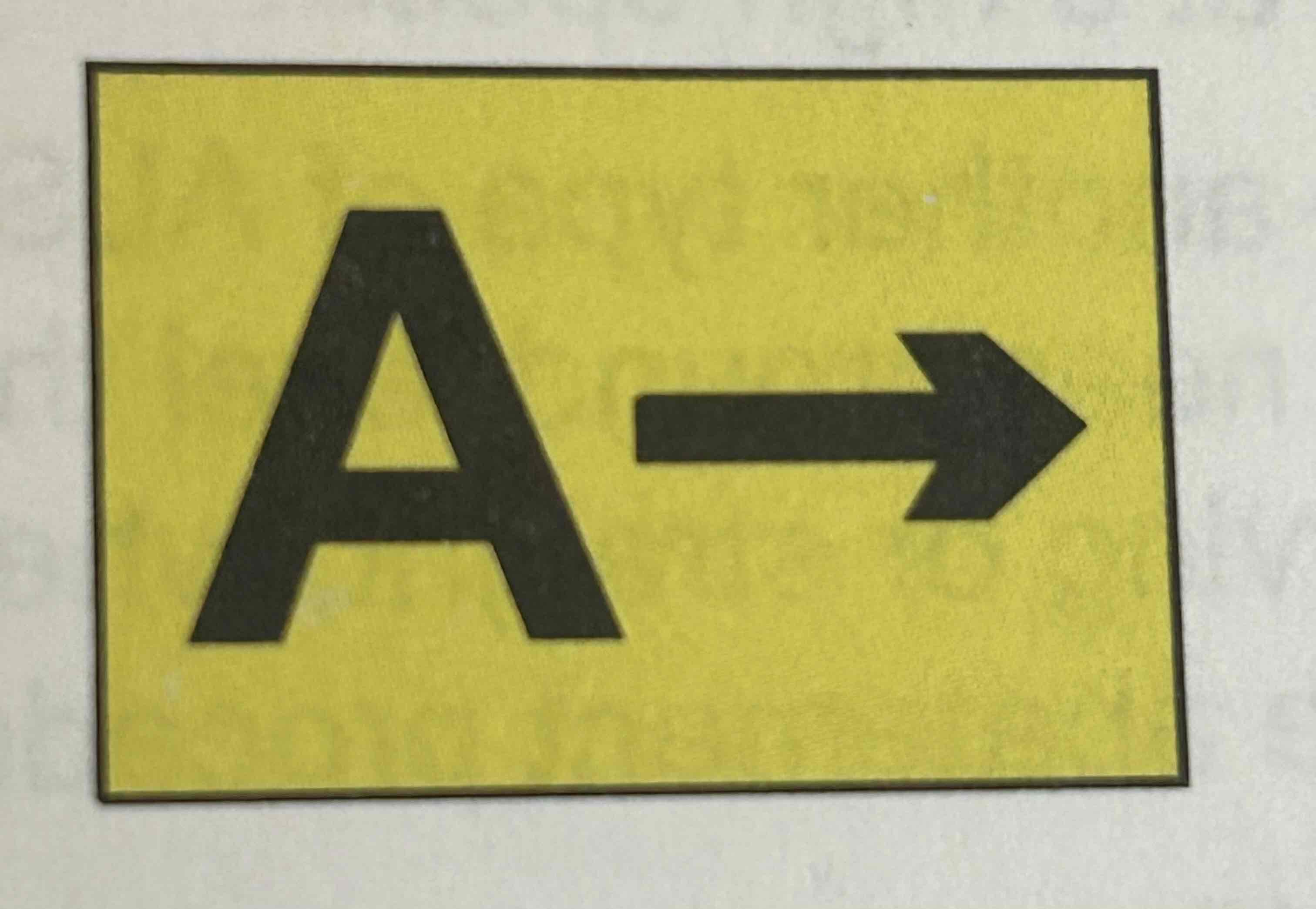
Destination Signs
Black characters on a yellow background indicating a destination on the airport. These signs always have an arrow showing the direction of the taxiing route to the destination.

Information Signs
Black characters on a yellow background. Used to provide pilot with information on things such as areas that cannot be seen from the control tower, applicable radio frequencies, and noise abatement procedures.
Runway distance remaining signs
Located along one or both side(s) of the runway. These signs have white numbers on a black background. Indicate the distance (in thousands of feet) of remaining runway.

Approach Light System (ALS)
Configuration of signal lights starting at the landing threshold and extending into the approach area.
LDN (lead-in light system)
Another form of ALS. Consists of one or more series of flashing lights installed at or near ground level that provide positive visual guidance along an approach path, either curving or straight, where special problems exist with hazardous terrain, obstructions, or noise abatement procedures.
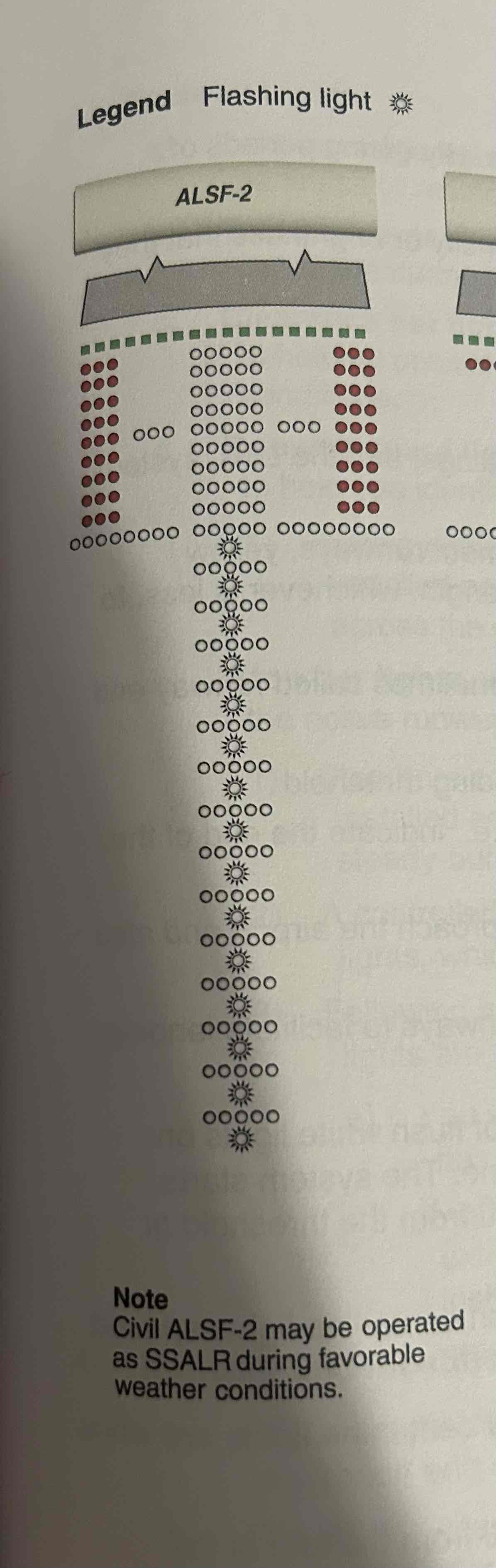
ALSF-2
Approach light system with SFL in the ILS category II configuration
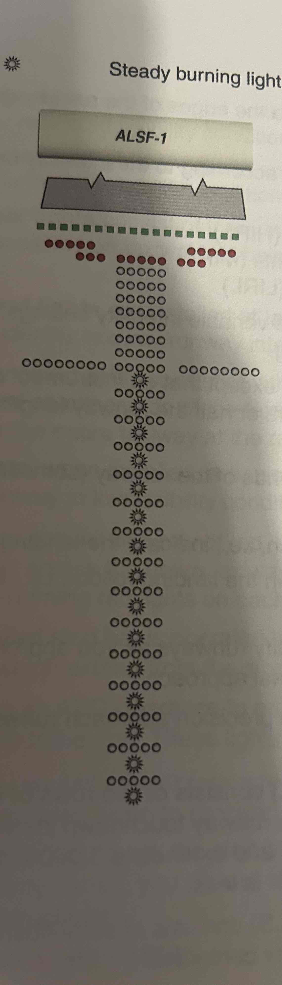
ALSF-1
Approach light system with SFL in the ILS category I configuration
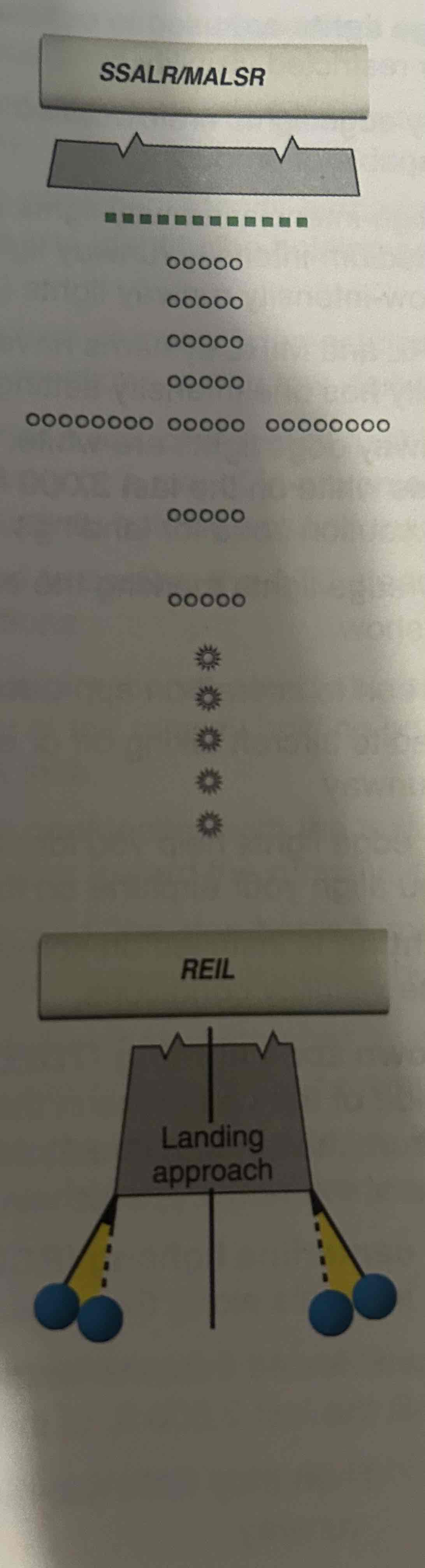
SSLAR/MALSR
Simplified short approach light system with runway alignment indicator lights (RAIL) / medium intensity approach light system with RAIL
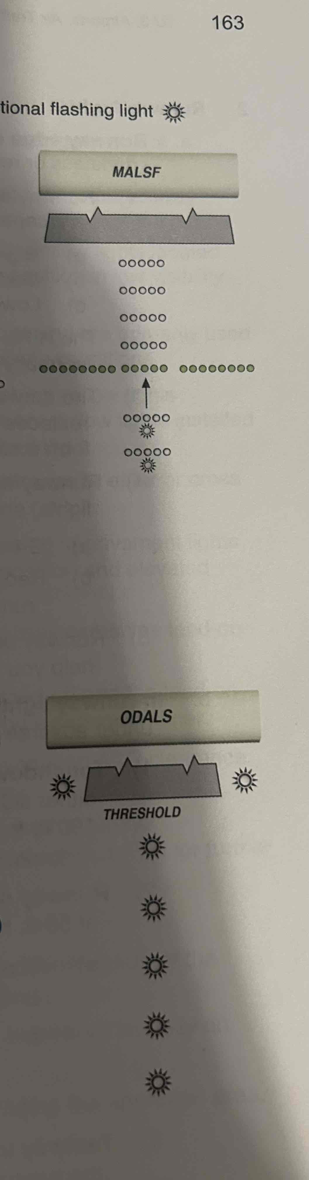
MALSF
Medium intensity approach light system with SFL
RAIL
A type of ALS consisting of sequenced flashing lights installed only to supplement other light systems
Runway edge lights
Used to outline the edges of the runway during periods of darkness or restricted visibility conditions
In-runway lighting
Installed on some precision approach runways to facilitate landing under adverse visibility conditions
Touchdown Zone Lighting (TDZL)
Consists of two rows of flush white lights on whether side of the centerline in the runway touchdown zone. The system starts 100 ft. From the landing threshold and extends to 3,000 ft. from the threshold or midpoint of the runway
Runway Centerline Lighting (RCLS)
Consists of semi-flush centerline lights spaced at 50-ft. intervals along the runway centerline
Taxiway lead off lights
Semi flush lights defining the curved path of travel from the runway centerline to a point on an exit taxiway to expedite movement of aircraft from the runway
Land and hold short lights
Row of five semi flush flashing white lights installed at the hold short point, perpendicular to the centerline of the runway on which they are installed
Taxiway edge lights
Blue and outline the edges of taxiways during periods of darkness or restricted visibility conditions
Taxiway centerline lights
Green and used on some airports to make the taxiway centerline during low visibility conditions
Clearance bar lights
Consist of three in-pavement steady-burning yellow lights located at holding positions on taxiways to help you identify the holding position in low visibility conditions
Runway guard lights
Installed at taxiway/runway intersections and are primarily used to help you identify taxiway/runway intersections during low visibility conditions
Stop bar lights
Used to confirm the ATC clearance to enter or cross the active runway in low visibility conditions
Runway End Identifier Lights (REIL)
Installed at many airports to provide rapid and positive identification of the approach end of a particular runway, consists of a pair of synchronized flashing lights located laterally on each side of the runway threshold
Pilot control of lighting (PCL)
Radio controlled lighting systems available where there is no operating control tower or FSS
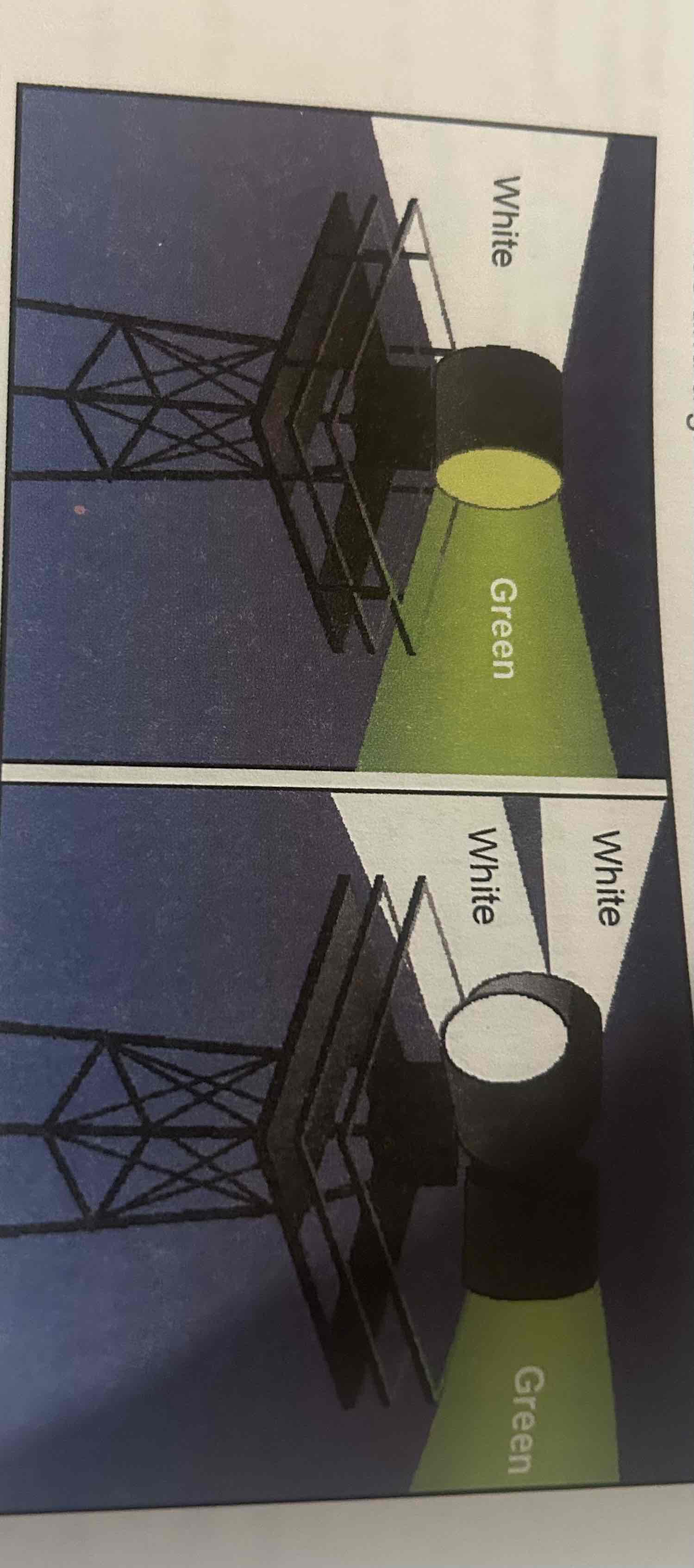
Airport Rotating Beacons
Beacons with the primary purpose of identifying the locations of airports at night. White and green means civil use, two whites and green means military.
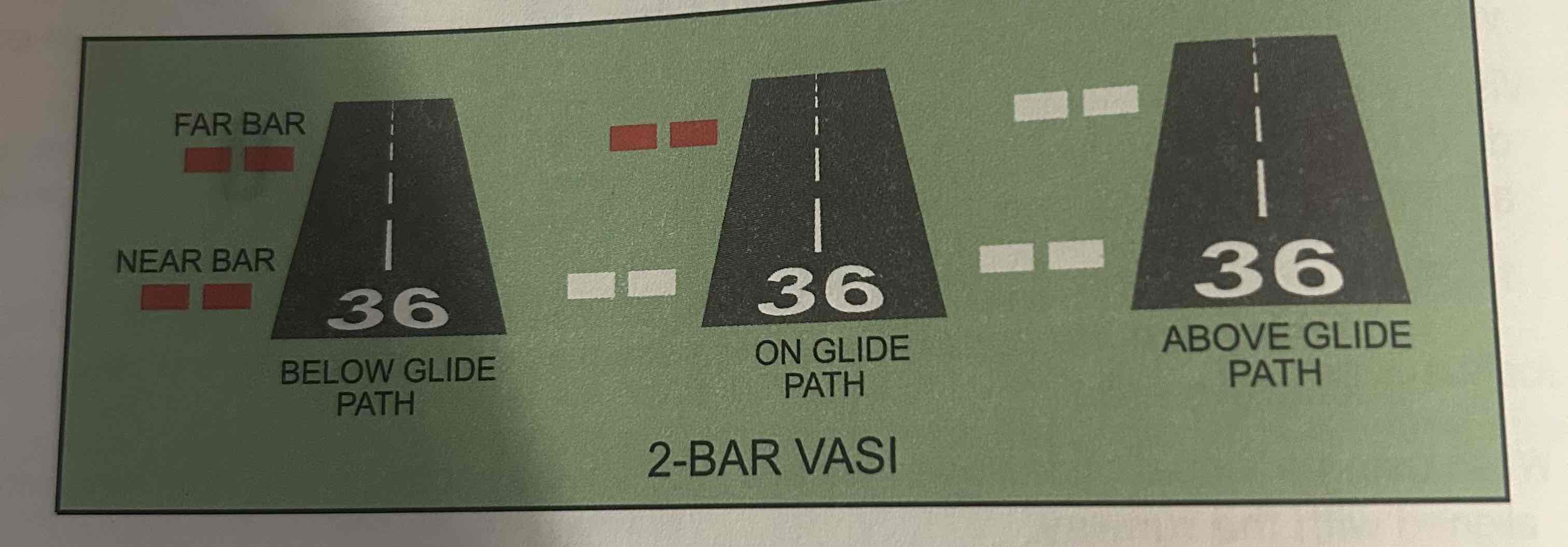
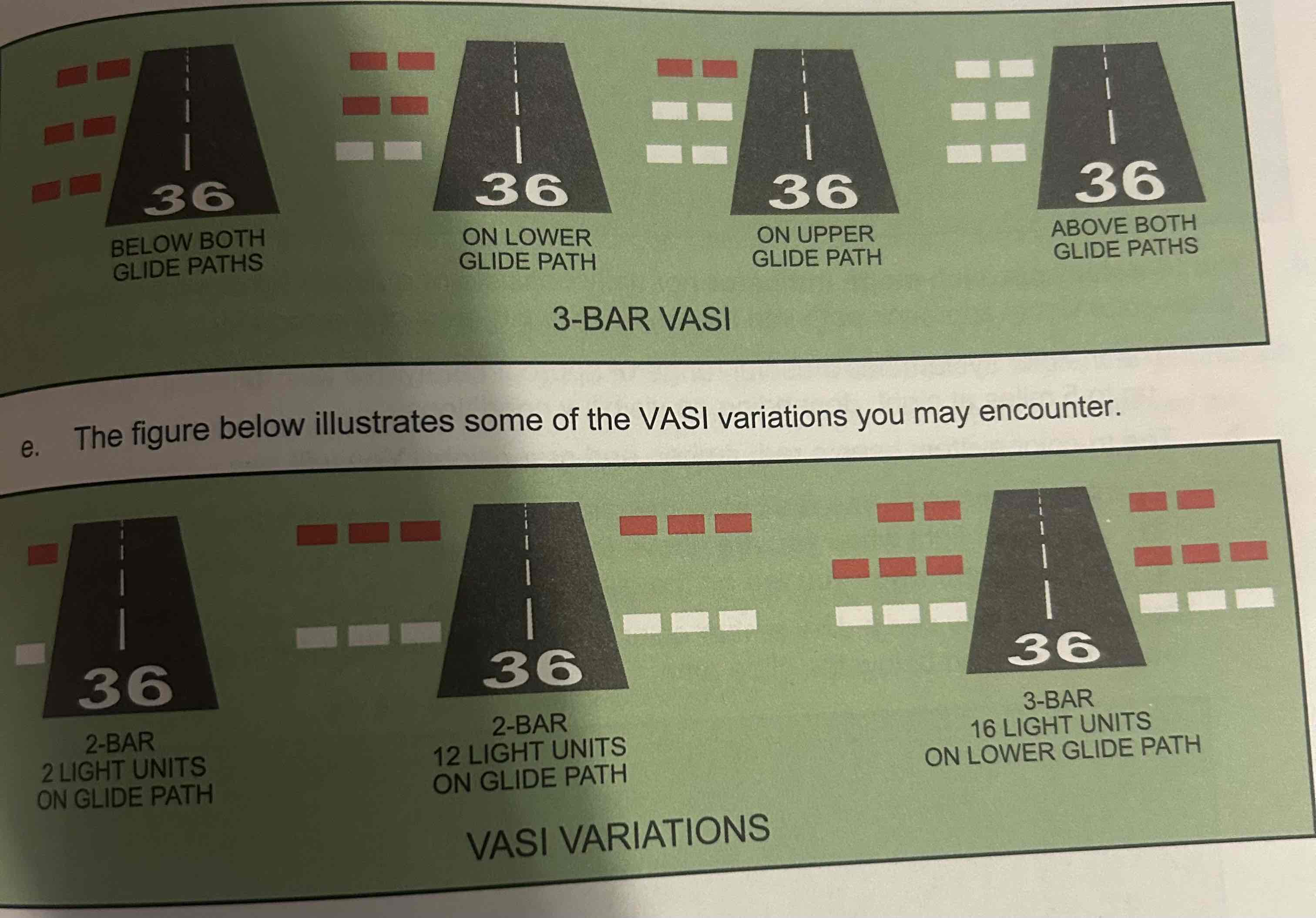
Visual approach slope indicator (VASI)
Systems of lights arranged to provide visual descent guidance during an approach, basically uses color differentiation between red and white
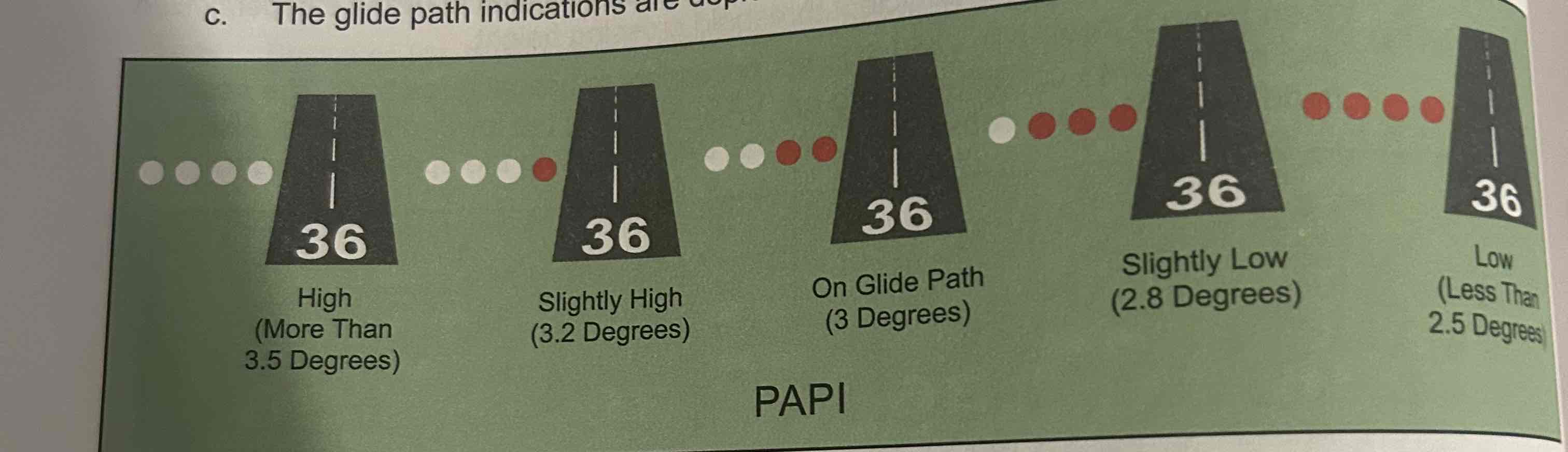
Precision approach path indicator (PAPI)
Uses lights similar to VASI but in a single row of either two or four lights, color differention between red and white to determine aircraft’s location with respect to runway
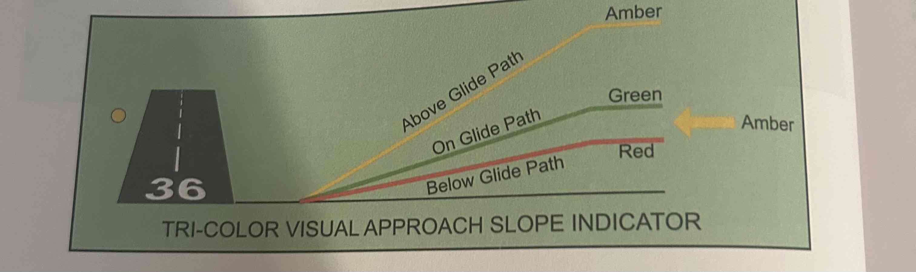
Tri-color approach slope indicator
Consists of a single light unit projecting a three color visual approach path into the final approach area of the runway
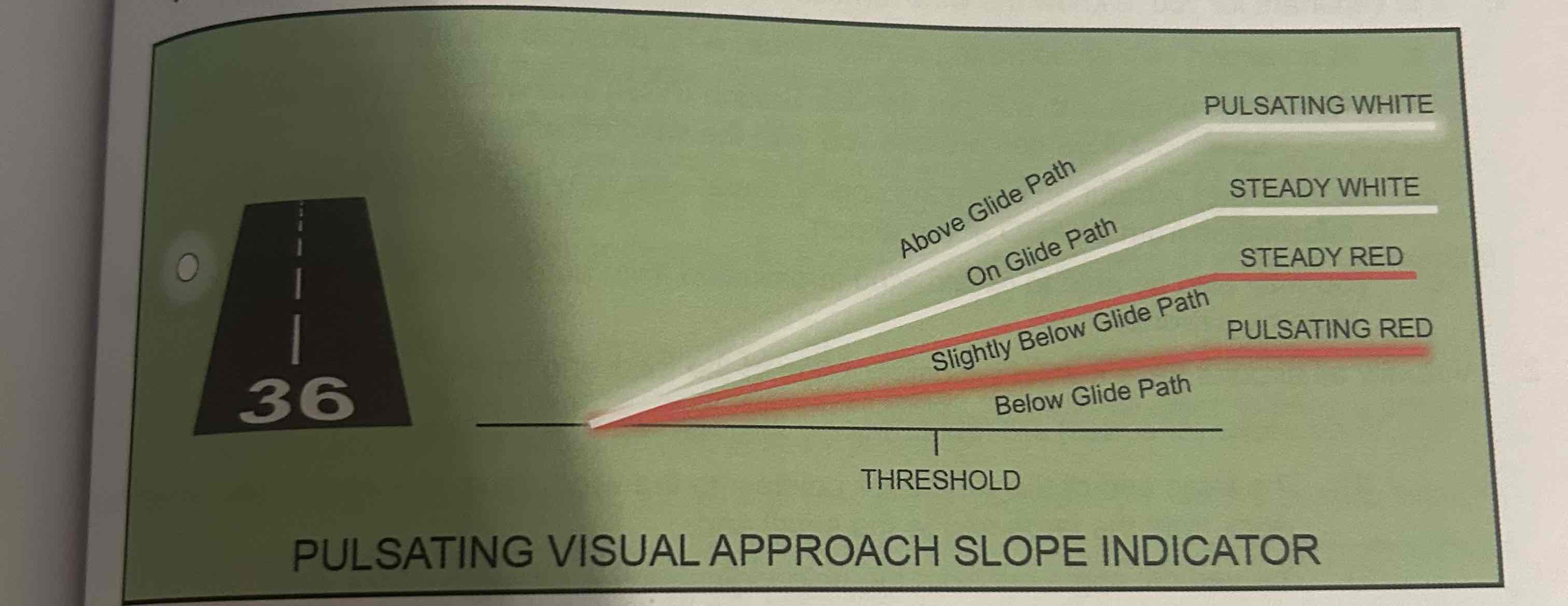
Pulsating visual approach slope indicators
Consists of a single light unit projecting a two color (red and white) visual approach path
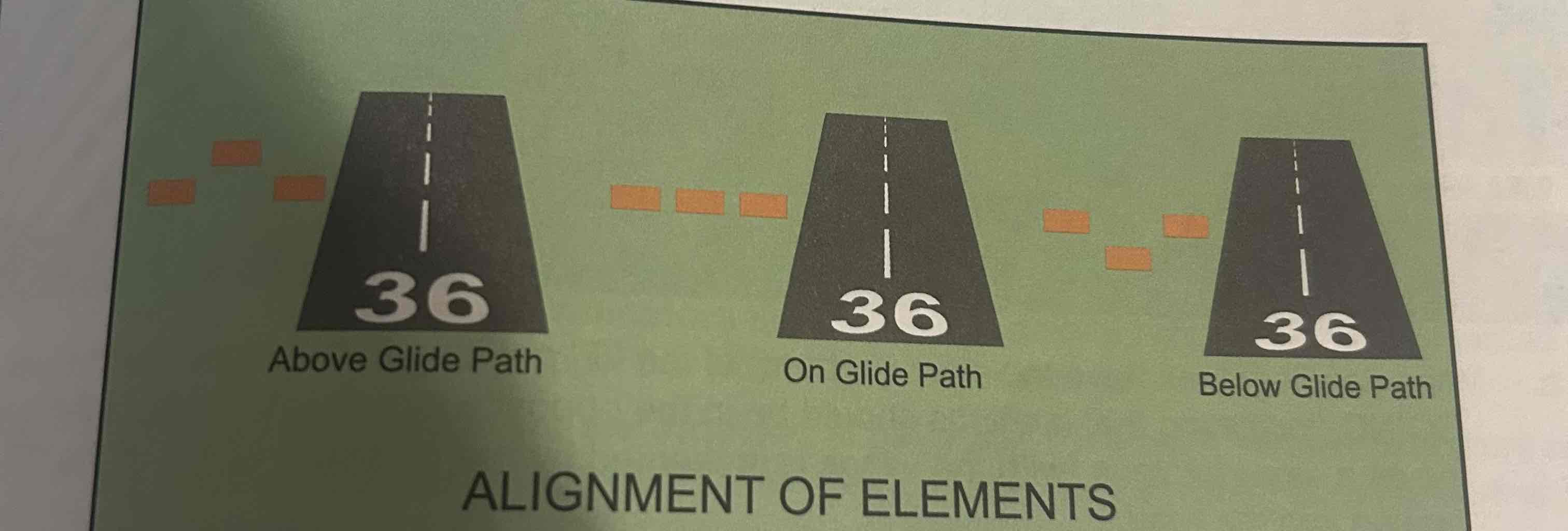
Alignment of elements system
Visual glideslope indicator, does not use lights instead using painted plywood panels which lineup when on glide path
Wind Tee
The stem (bottom) of the “T” pointing in the direction the wind is GOING
Tetrahedrons
Point to the direction from which the wind is COMING
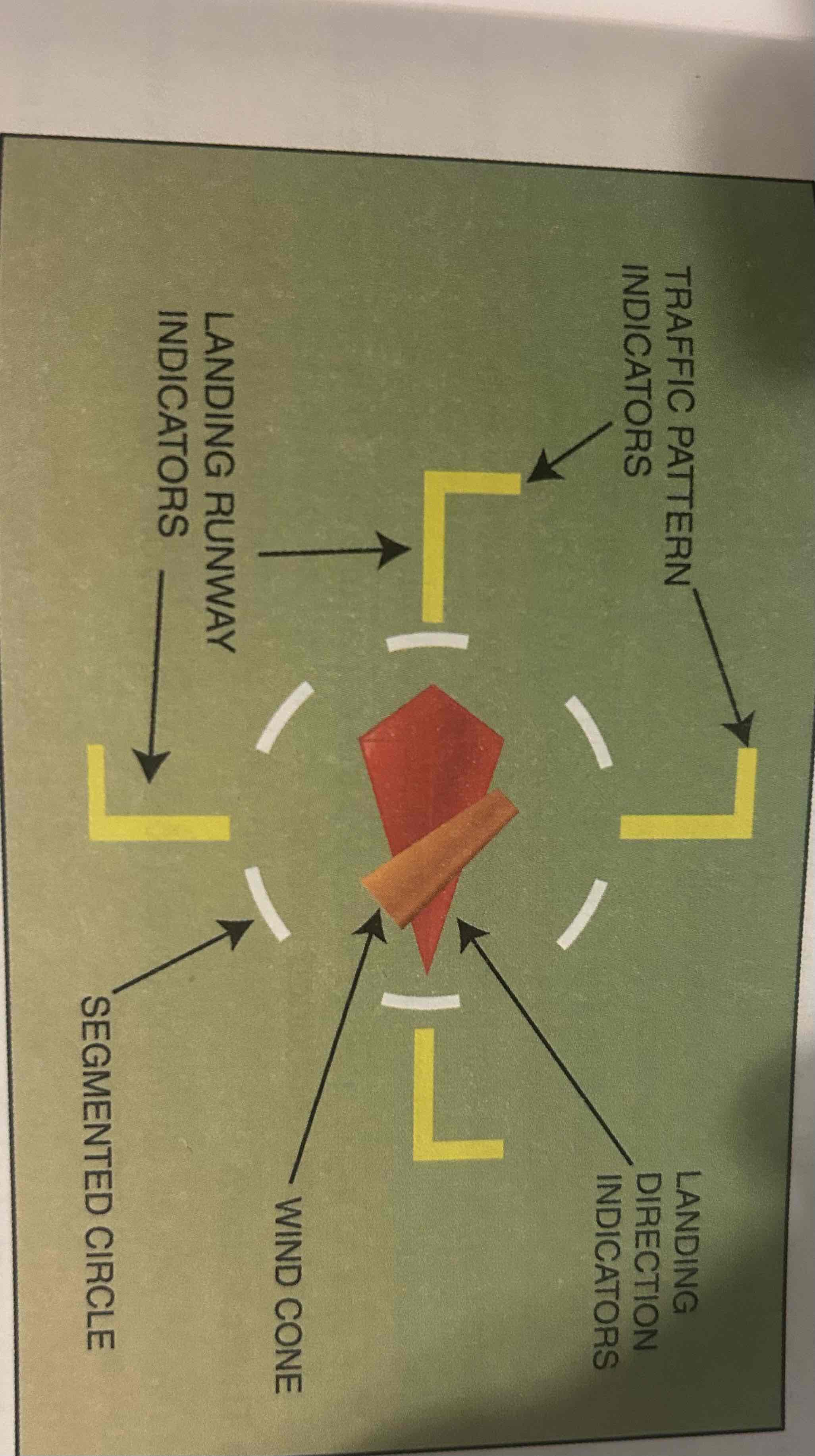
Segmented Circle
Located in a position affording maximum visibility to pilots in the air and on the ground. A wind and/or landing direction indicator is usually in the center
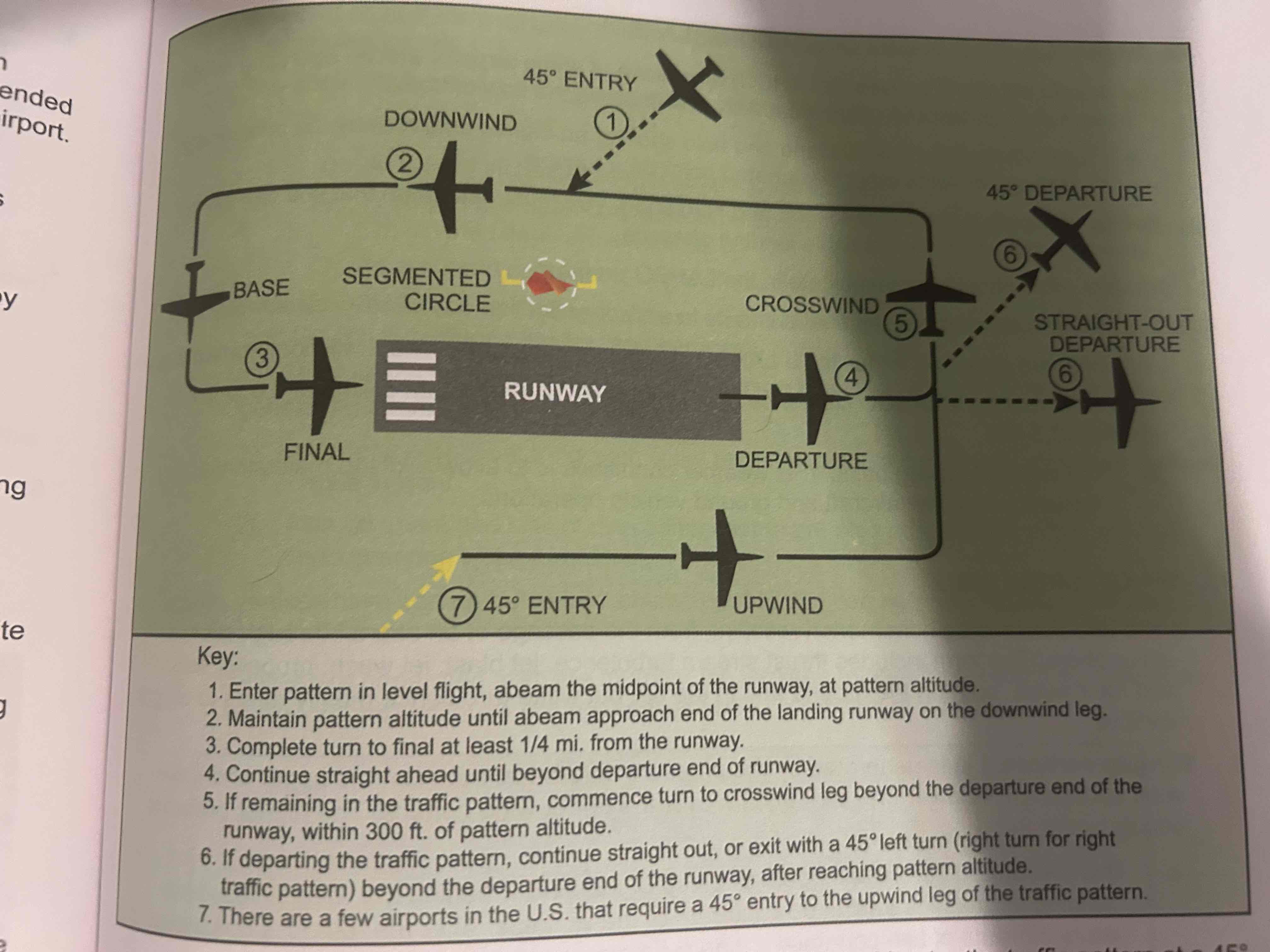
Departure leg
Straight course aligned with and leading from the takeoff runway

Crosswind leg
Horizontally perpendicular to the extended centerline of the takeoff runway. Entered by making a 90 degree turn from the upwind leg

Downwind leg
Flown parallel to the landing runway but in a direction opposite to the intended landing direction

Base leg
transitional part of the traffic pattern between the downwind leg and the final approach leg

Final approach leg
Descending flight path starting at the completion of the base-to-final turn and extending to the point of touchdown
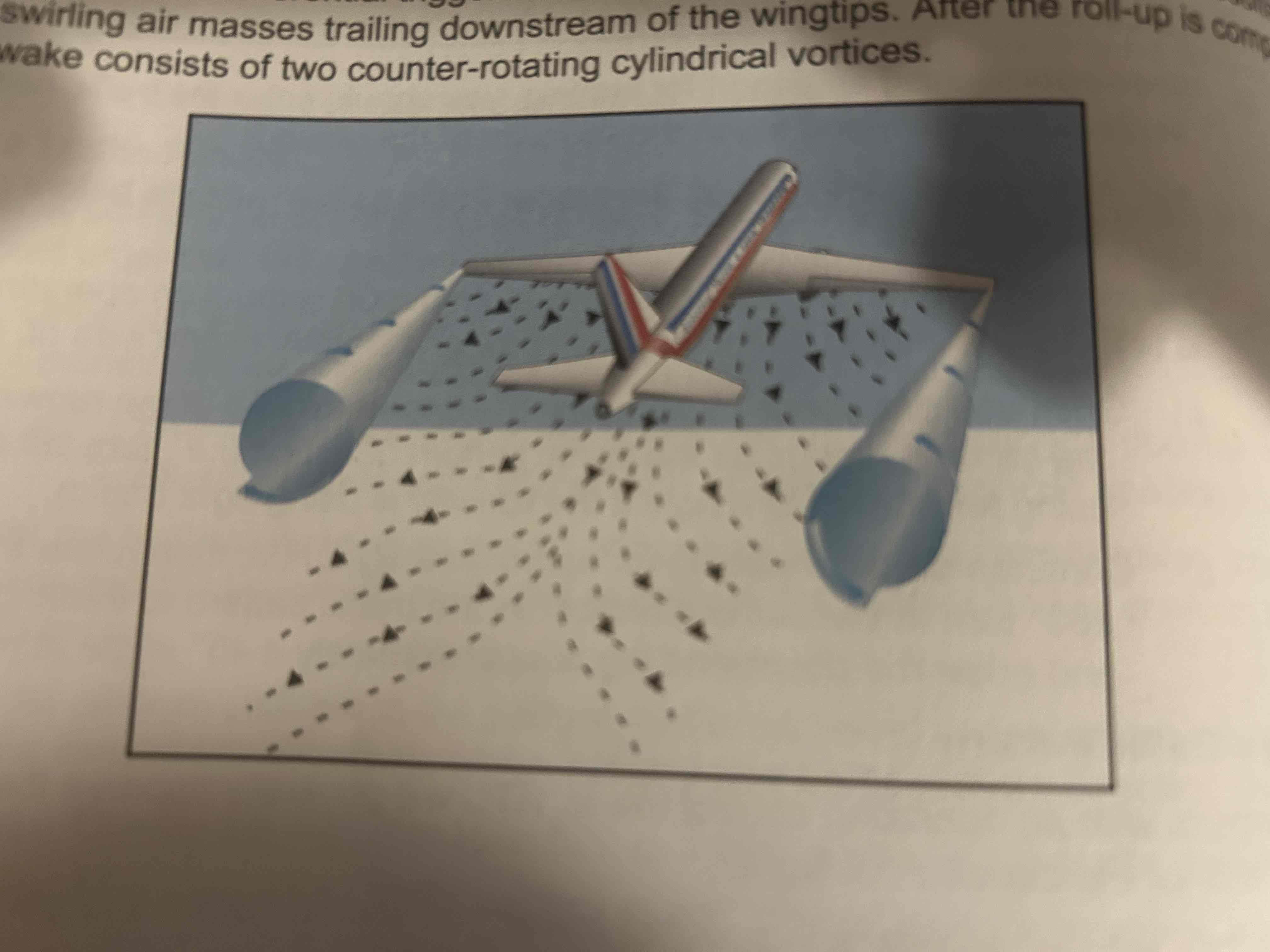
Wake turbulence
Phenomenon resulting from the passage of an aircraft through the atmosphere. Refers mostly to wingtip vortices.
Wingtip vortices
the pressure differential between the upper and lower wing surfaces triggers a roll up of the airflow behind the wing, resulting in swirling air masses trailing downstream of the wingtips
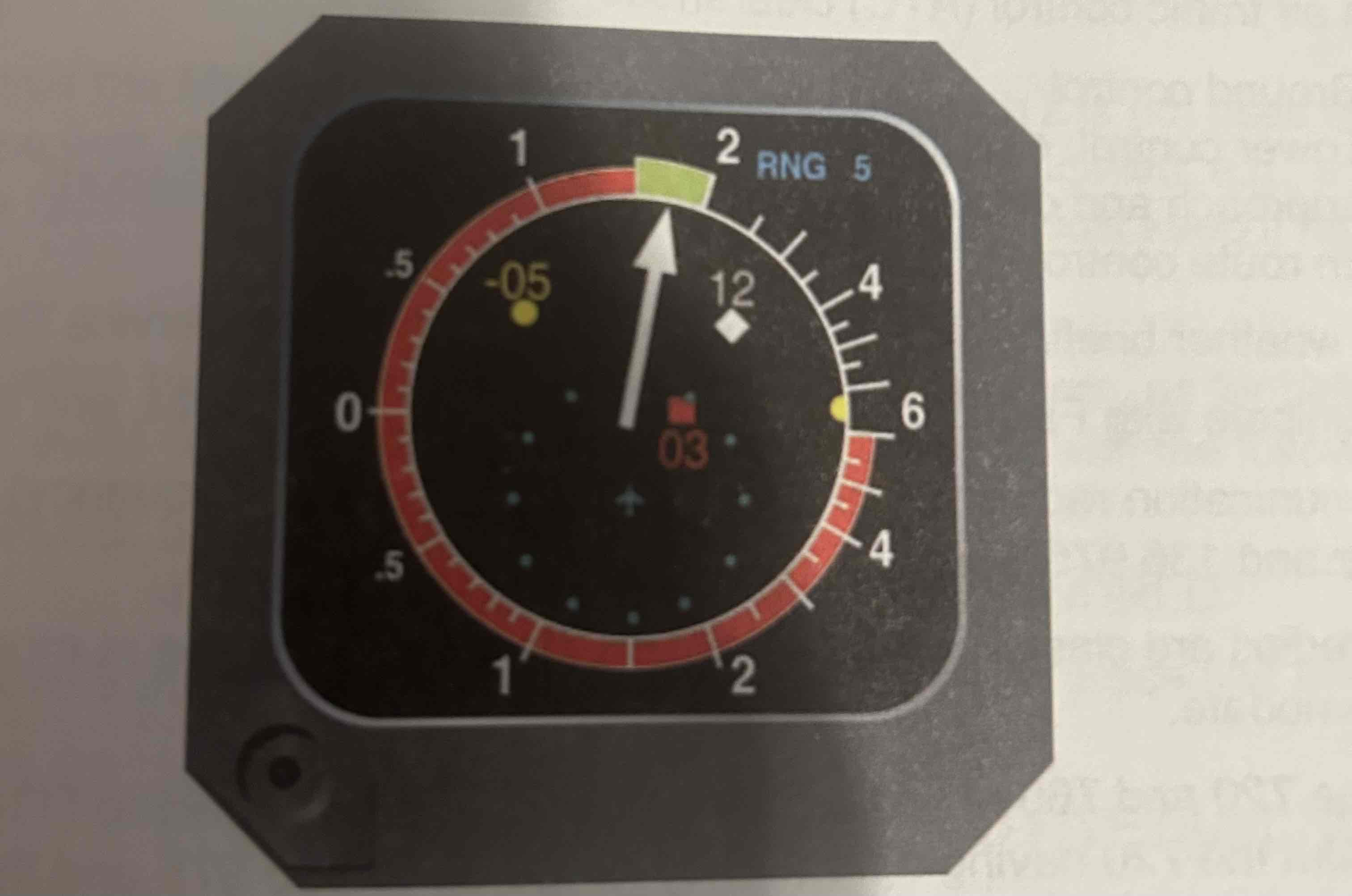
Traffic Alert and Collision Avoidance System (TCAS)
An active system (emits interrogation signals and does not rely on ground radar) that can detect aircraft transponder signals
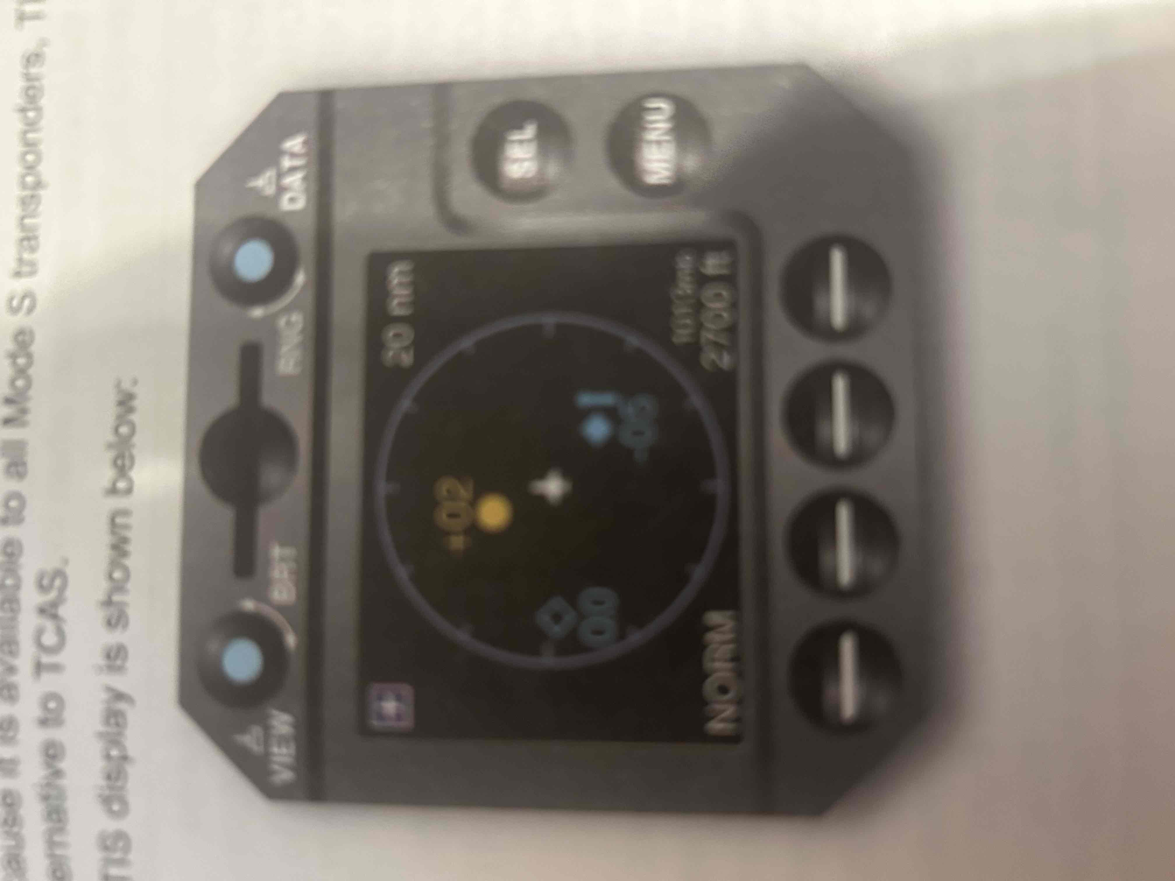
Traffic information system (TIS)
A passive system (relies on transponder replies triggered by ground and airborne components) that can detect aircraft

class A airspace
Applicable from 18,000 ft. MSL up to and including flight level 600

Class C airspace
Surrounds those airports that have an operational control tower, are serviced by a radar approach control, and have a certain number of IFR operations or passenger enplanements

Class D airspace
Surrounds those airports that have both an operating control tower and weather services available and are not associated with class b or class c airspace
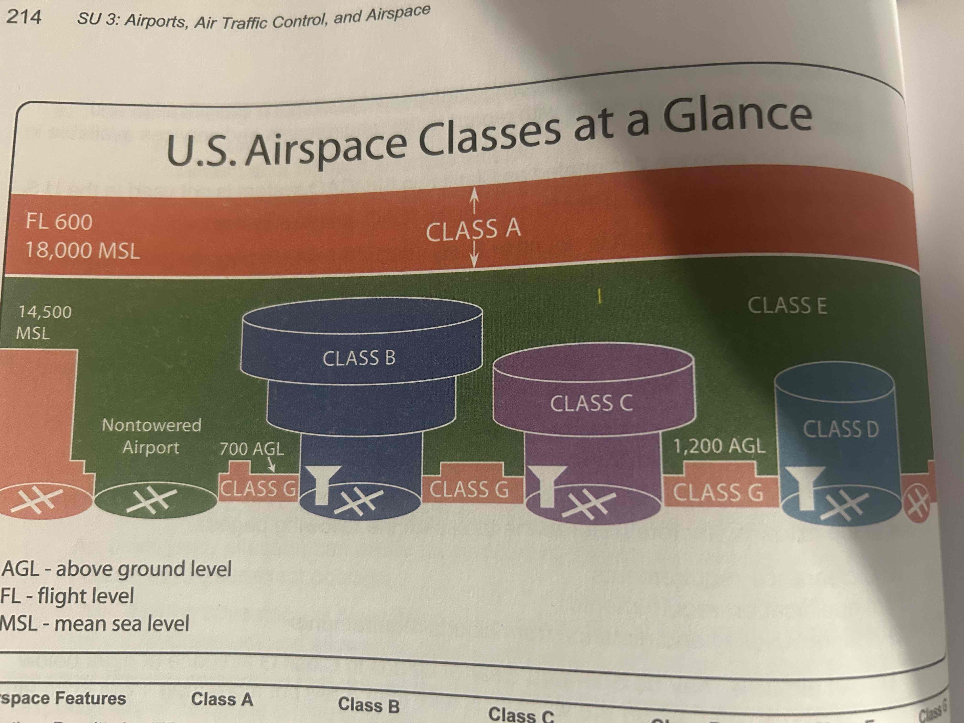
Class E airspace
Controlled airspace that is not classified a,b,c, or d

Class G airspace
Airspace that has not been designated any of the above letters