topic 7 - magnetism and electromagnetism
1/83
Earn XP
Description and Tags
Name | Mastery | Learn | Test | Matching | Spaced |
|---|
No study sessions yet.
84 Terms
state what the poles of a magnet are
places where the magnetic forces are strongest
state what happens when two magnets are brought close together
they exert a force on each other
state what happens when two like poles are brought close together
they repel each other
state what happens when opposite poles are brought close together
they attract each other
state what kind of force attraction between magnetic poles is
non-contact force
state what kind of force repulsion between magnetic poles is
non-contact force
state what induced magnetism causes
a force of attraction
state what happens when an induced magnet is removed from a magnetic field
it loses most/all of its magnetism quickly
state what a permanent magnet is
an object where its magnetism cannot be induced or removed
state what an induced magnet is
an object where its magnetism can be induced or removed
explain what a magnetic field is
a region around a magnet
where a force acts on another magnet/magnetic material
state what the force is between a magnet and magnetic material
attraction
state what the strength of a magnetic field depends on
the distance from the magnet
state where a magnetic field is strongest
at the poles of the magnet
state what determines the direction of a magnetic field at any given point
direction of force
that would act on
another north pole
placed at that point
state the direction of magnetic field lines
north pole → south pole
state what a magnetic compass contains
small bar magnet
state what kind of field the earth has
magnetic field
state what direction a magnetic compass’ needle points in
direction of earth’s magnetic field
describe how to plot the magnetic field pattern of a magnet using a compass
place a magnet on top of a piece of paper and draw a dot at one corner of the magnet
place a plotting compass next to the dot, so that one end of needle of the compass points away from the dot
use a pencil to draw a new dot at the other side of the compass needle
move the compass so that it points away from the new dot and draw a new dot at the other side of the compass needle
repeat this process until there is a chain of dots going from one end of the magnet to the other
repeat the entire process several times to create several other magnetic field lines
explain how the behaviour of a magnetic compass is related to evidence that the core of the earth must be magnetic
on earth, in the absence of any magnets or magnetic materials
a magnetic compass will always point north
this evidences that earth’s core is magnetic
and creates its own magnetic field
state where the magnetic poles of earth’s magnetic field are
magnetic north pole = antarctica
magnetic south pole = arctic
state what happens when current flows through a conducting wire
magnetic field is produced
around the wire
state what the strength of a conducting wire’s magnetic field relies upon
current through the wire
distance of the field from the wire
state what shaping a wire to form a solenoid does
increases the strength
of the magnetic field
created by a current
through the wire
state the nature of a magnetic field in a solenoid
strong
uniform
state the shape of the magnetic field around a solenoid
similar to a bar magnet
state what increases the strength of a solenoid’s magnetic field
adding an iron core
state electromagnet definition
solenoid
with an iron core
describe how the magnetic effect of a current can be demonstrated
place a conducting wire in between two bar magnets
allow current to flow through the wire
this will create a magnetic field
this causes a force to push the wire at right angles
explain how a solenoid arrangement can increase the magnetic effect of current
increase current
increase number of turns in coil
add an iron core
describe how to determine the direction of a magnetic field
use right-hand thumb rule
thumb points in direction of current flow
rest of fingers give direction of the field lines
state what the magnetic field of a conducting wire is made up of
concentric circles
with no poles
state what happens to the magnetic field of a conducting wire as distance from the wire increases
concentric circles get further apart
state what happens to the magnetic field of a conducting wire when you reverse the direction of current
the magnetic field direction will reverse
state motor effect definition
when a conductor carrying a current
is placed in a magnetic field
the magnet producing the field
and the conductor
will exert a force on each other
describe how fleming’s left hand rule shows the orientation of force, current in a conductor and magnetic field
direction of a force on
a conductor carrying current
depends on the direction of current
and the direction of the magnetic field
all three are PERPENDICULAR to each other
thumb - force orientation
pointer finger - magnetic field orientation
middle finger - current orientation
state the factors that affect the size of the force on a conductor
current - larger current = larger force
length - larger length = larger force
magnetic flux density - larger density = more magnetic field lines = larger force
state symbol equation to calculate force for a conductor
F (N) = B (T) x I (A) x L (m)
state the basis of an electric motor
coil of wire carrying a current
in a magnetic field
tends to rotate
state what the motor effect can be used to make
simple d.c. electric motor
describe what a simple d.c. electric motor consists of
coil of wire
positioned in a uniform magnetic field
the coil of wire, when horizontal, forms a complete circuit with a cell
coil of wire attached to a split-ring commutator
split ring is connected in a circuit with a cell via contact with conducting carbon brushes
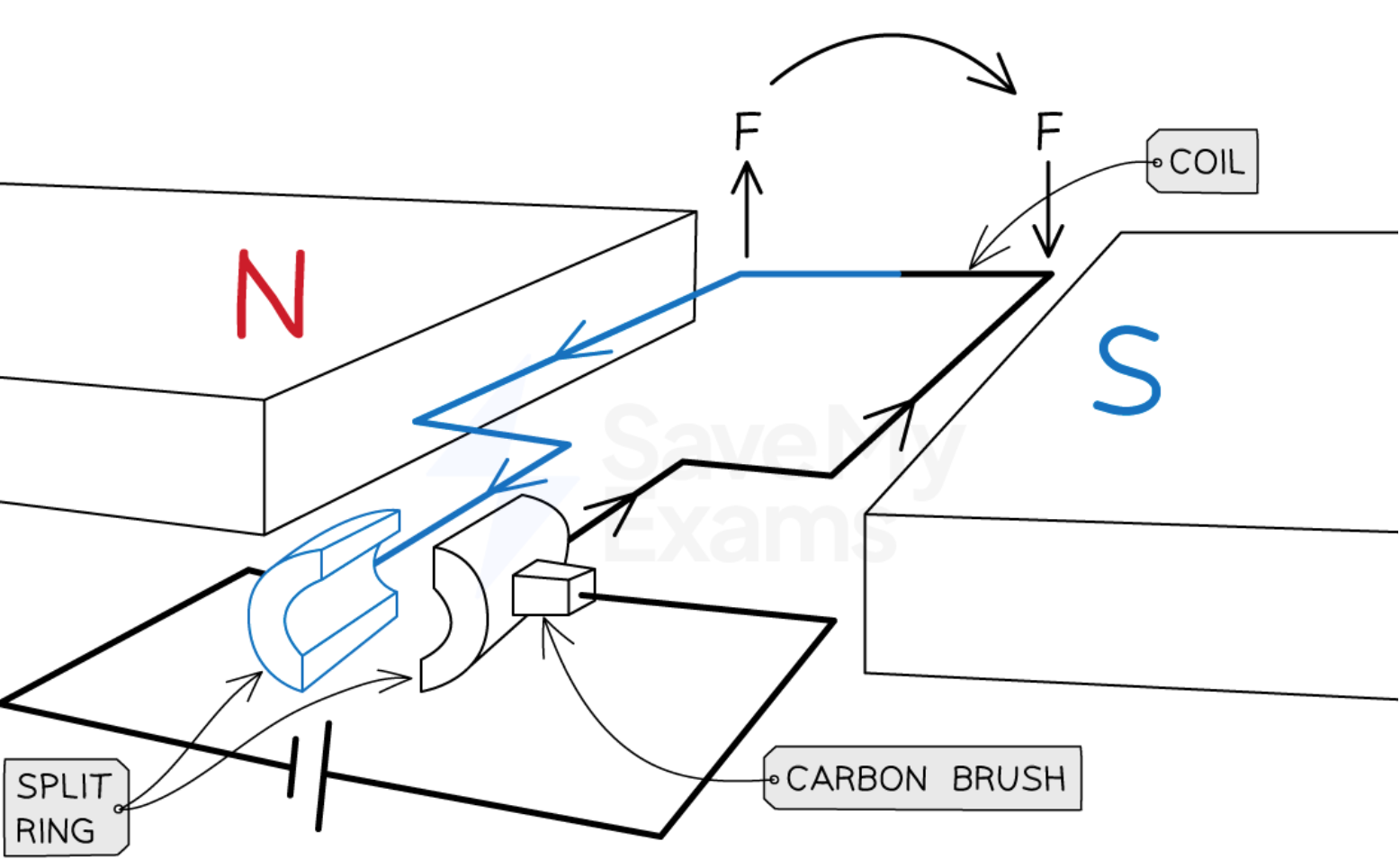
explain how the force on a conductor in a magnetic field causes the rotation of the coil in an electric motor
current flowing through the coil produces a magnetic field around the coil
this magnetic field interacts with the uniform external field
so a force is exerted on the wire
forces act in opposite direction on each side of the coil
causing it to rotate and the coil is now in a vertical position
on the side of the coil on top, current is flowing towards the cell
so the force acts downwards
on the side of the coil on the bottom, current is flowing away from the cell
so the force acts upwards
once the coil has rotated 90°, the split ring is no longer in contact with the brushes
so no current flows through the coil
thus no forces act on the coil
explain how momentum of a conductor in a magnetic field causes the continued rotation of the coil in an electric motor
with the coil in vertical position, even with no forces acting upon it
momentum of the coil causes it to slightly rotate
this causes the split ring to make contact with the carbon brushes again
and current flows through the coil again
current flows towards the cell on the left side of the coil
and away from the cell on the right
even though the coil has flipped
the left side of the coil experiences an upwards force
and the right side of the coil experiences a downwards force
causing the coil to continue to rotate in the same direction
forming a continuously spinning motor
describe why loudspeakers and headphones use motor effect
to convert variations in current
in electrical circuits
to the pressure variations
in sound waves
explain how a moving-coil loudspeaker/headphones works
loudspeaker/headphones consists of a coil of wire wrapped around one pole of a permanent magnet
an alternating current flows through the coil, creating a changing magnetic field around the coil
magnetic field around the coil interacts with the field from the permanent magnet
interacting magnetic fields will exert a force on the coil
direction of the force is determined by fleming’s left-hand rule
as direction of the magnetic field is constantly changing, the force exerted on the coil will constantly change direction
which makes the coil oscillate
the oscillating coil causes the speaker cone to oscillate
which makes the air oscillate, creating sound waves
state what induces a potential differences across the ends of a conductor
if the conductor moves relative to a magnetic field
or if there is a change in the magnetic field around the conductor
state generator effect definition
if a conductor with induced potential difference across its ends
is part of a complete circuit
where current is then induced in the conductor
state what an induced current generates
magnetic field
that opposes the original change
which was either the movement of the conductor relative to a magnetic field
or the change in the conductor’s magnetic field
state factors that increases the size of induced potential difference/current
magnetic field strength increases
number of turns of the coil increases
speed conductor is moved at increases
state factors that affect the direction of induced potential difference/current
direction of magnetic field
direction of wire/coil
state how the generator effect is used in an alternator
to generate a.c.
state how the generator effect is used in a dynamo
to generate d.c.
state what a simple alternator is
device
which converts energy
from motion
into an electrical output
state what a simple alternator consists of
rotating coil of wire
between the poles of a permanent magnet
slip rings and brushes
connected to an external circuit
explain why a permanent magnet is used in a simple alternator/dynamo
to provide a uniform magnetic field
explain why a rotating coil is used in a simple alternator/dynamo
to cut the magnetic field as it rotates
and to allow an induced current to flow
explain why slip rings are used in a simple alternator
to allow the alternating current to flow
between the coil
and the external circuit
explain why carbon brushes are used in a simple alternator/dynamo
to provide a good electrical connection
between the coil and the external circuit
explain how the generator effect is used to generate a.c. in an alternator
rectangular coil rotates in a unform magnetic field due to the motor effect
coil is connected to an external circuit via slip rings and carbon brushes
the induced potential difference in the coil is measured by adding a galvanometer to the external circuit
potential difference is induced in the coil as the coil’s rotation cuts the magnetic field lines
the pointer on the galvanometer defects one way, then the opposite way, then back again
which indicates the size and direction of the induced potential difference is constantly changing
as a result of the alternating potential difference, an alternating current is produced as the coil rotates
this continues as long as the coil keeps rotating in the same direction
state when and explain why a maximum potential difference is induced in a simple alternator
position of the coil is horizontal
motion of the coil is perpendicular to the magnetic field
because the largest number of magnetic field lines are cut
when the motion of the coil is perpendicular
state when no potential difference is induced in a simple alternator
position of the coil is vertical
motion of the coil is parallel to the magnetic field
because no magnetic field lines are cut
when the motion of the coil is parallel
state what a dynamo is
device
that converts
an electrical input
into motion
state what a simple dynamo consists of
rotating coil of wire
between the poles of a permanent magnet
split ring commutator and brushes
connected to an external circuit
explain why a split ring commutator is used in simple dynamos
to allow the connection
between the coil and the external circuit
to change
every half turn
explain how the generator effect is used to generate d.c. in a dynamo
as the coil rotates, due to the motor effect, it cuts through the magnetic field lines
this induces a potential difference between the end of the coil
the split ring commutator changes the connections between the coil and the brushes every half turn
in order to keep the current leaving the dynamo in the same direction
this happens each time the coil is perpendicular to the magnetic field lines
thus, the induced potential difference doesn’t reverse its direction (unlike in alternators)
instead, the potential difference varies from zero to a maximum value twice each cycle of rotation
and never changes polarity
meaning that the current is always positive/negative
state what bicycle dynamo is used for
to supply electricity
to bike lights
whilst in motion
explain how the generator effect is used to generate d.c. in a bicycle dynamo
a bicycle dynamo consists of a rotating magnet placed inside a coil
the magnet is rotated by its connection to the bicycle inside the coil
the magnetic field lines cut through the sides of the coil
inducing a potential difference in the coil
since the magnetic field direction is constantly changing as it rotates
the potential difference alternates direction
meaning the output current alternates direction
causing the bike light to illuminate
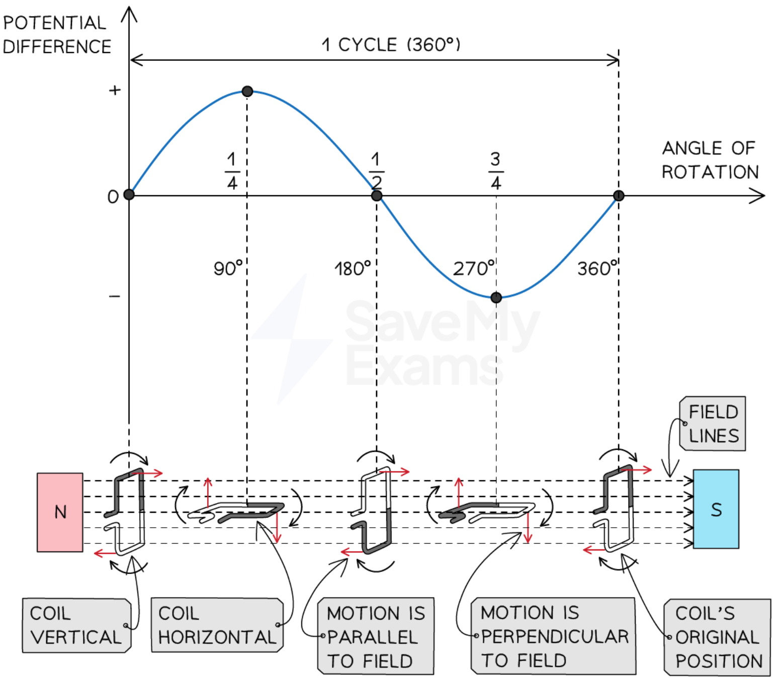
explain how to interpret graphs of potential difference generated in the coil against time (ALTERNATOR)
the shape of the graph is a sine or cosine curve (depending on coil starting position)
when the coil is vertical at 0°, its motion is parallel to the magnetic field, causing the induced p.d. size to be 0
when the coil has rotated by 90°, its position is horizontal, its motion is perpendicular to the magnetic field, causing the induced p.d. size to be its maximum value
when the coil has rotated by 180°, its position is vertical again, its motion is parallel to the magnetic field, causing the induced p.d. size to be 0
when the coil has rotated by 270°, its position is horizontal again, its motion is perpendicular to the magnetic field, causing the induced p.d. size to be its maximum value and opposite in direction to the value at 90°
when the coil has rotated by 360°, its position is at its starting point, its motion is parallel to the magnetic field, causing the induced p.d. size to be 0
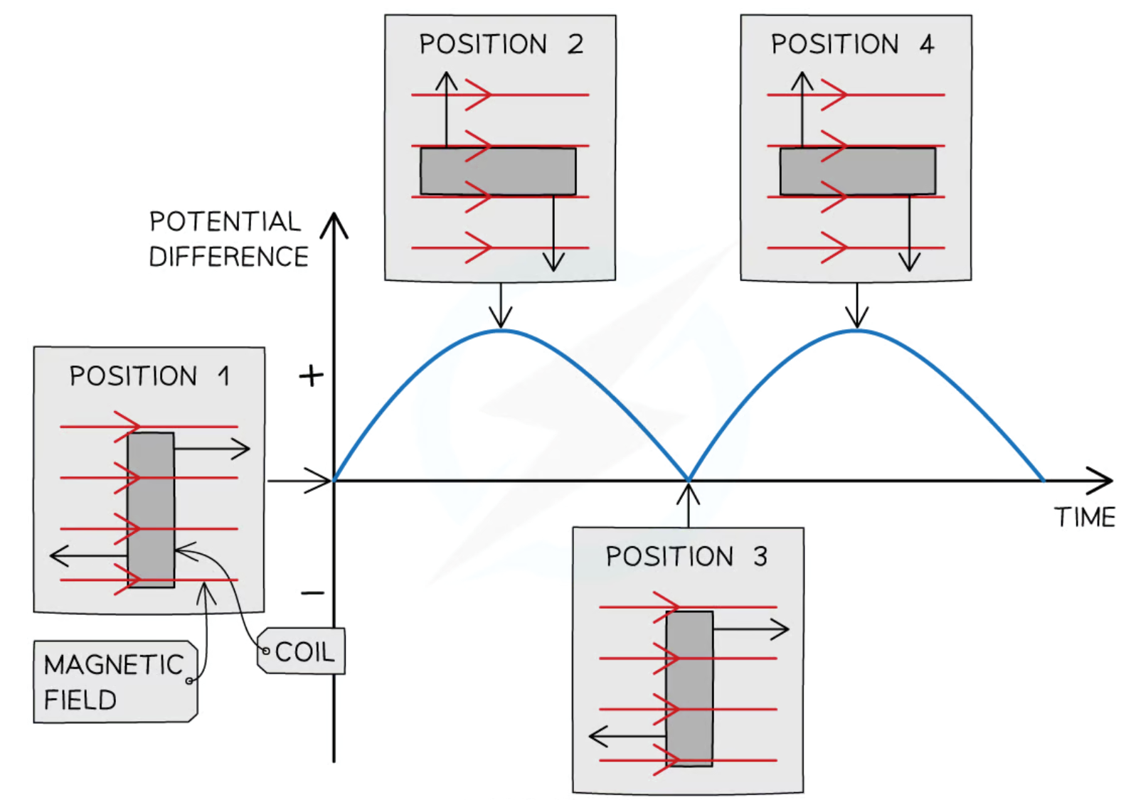
explain how to interpret graphs of potential difference generated in the coil against time (DYNAMO)
the shape of the graph is a sine curve and is always in the same direction
when the coil is vertical at 0°, its motion is parallel to the magnetic field, causing the size of the induced p.d. to be 0
when the coil has rotated by 90°, its position is horizontal, its motion is perpendicular to the magnetic field, causing the induced p.d. size to be its maximum value
when the coil has rotated by 180°, its position is vertical again, its motion is parallel to the magnetic field, causing the induced p.d. size to be 0
when the coil has rotated by 270°, its position is horizontal again, its motion is perpendicular to the magnetic field, causing the induced p.d. size to be its maximum value and in the same direction to the value at 90°
when the coil has rotated by 360°, its position is at its starting point, its motion is parallel to the magnetic field, causing the induced p.d. size to be 0
state the factors affecting alternator/dynamo output
frequency of coil rotation
number of turns on the coil
strength of magnet
inserting a soft iron core into the coil
describe why microphones use generator effect
to convert the pressure variations
in sound waves
into variations in current
in electrical circuits
explain how a moving-coil microphone works
when sound waves reach the microphone
the pressure variations cause the diaphragm to vibrate
this causes the coil to move back and forth
through the magnetic field produced by the magnet
as the coil moves, it cuts through the field lines
inducing a potential difference in the coil
the induced potential difference will be alternating
because the coil is continually changing direction
due to the vibrations of the diaphragm
state what a basic transformer consists of
primary coil
and a secondary coil
wound on an iron core
state why iron is used in transformers
because it’s easily magnetised
state the ratio of the potential difference in a transformer to number of turns in a coil
Vp / Vs = Np / Ns
state the ratio of voltage in a step-up transformer
Vs > Vp
state the ratio of voltage in a step-down transformer
Vp > Vs
state what would happen if transformers were 100% efficient
electrical power output = electrical power input
state ratio of voltage to current (power input : power output) in a transformer
Vp x Ip = Vs x Is
explain how a transformer works
an alternating current is supplied in the primary coil
meaning it will produce a changing magnetic field around the primary coil
the iron core is easily magnetised
so the changing magnetic field passes through it
thus, there is now a changing magnetic field in the secondary coil
this changing field cuts through the secondary coil
and induces an alternating potential difference
the alternating potential difference will have the same frequency as the alternating current supplied to the primary coil
if the secondary coil is part of the complete circuit, it will cause an alternating current to flow
describe how the ratio of the potential differences across the two coils depends on the number of turns on each coil
the higher the number of turns
the higher the potential difference induced will be
state the role of transformers
increases p.d. of electricity before it is transmitted across the national grid
lowers high voltage electricity used in power lines to the lower voltages used domestically
used in adapters to lower mains voltage to the lower voltages used by many electronic devices
explain the advantages of high voltage transmission
when electricity is transmitted over large distances, the current in the wires heats them, resulting in energy loss
to transmit the same amount of power as the input power, the p.d. at which electricity is transmitted should be increased
resulting in a smaller current being transmitted through the power lines
because P = I x V, so if V increases, I must decrease to transmit the same power
a smaller current flowing through the power lines results in less heat being produced in the wire
resulting in a reduction of energy loss in the power lines