Paper 3 - Unit 15 - Hardware and Virtual Machines
1/61
There's no tags or description
Looks like no tags are added yet.
Name | Mastery | Learn | Test | Matching | Spaced | Call with Kai |
|---|
No analytics yet
Send a link to your students to track their progress
62 Terms
Combinational Circuit
A circuit whose output is solely determined by its input values.
e.g. half adder, full adder
Sequential Circuit
A circuit whose output is a function of its input values and the current state of the circuit (i.e. the output is fed back as input).
e.g. flip flops, latches
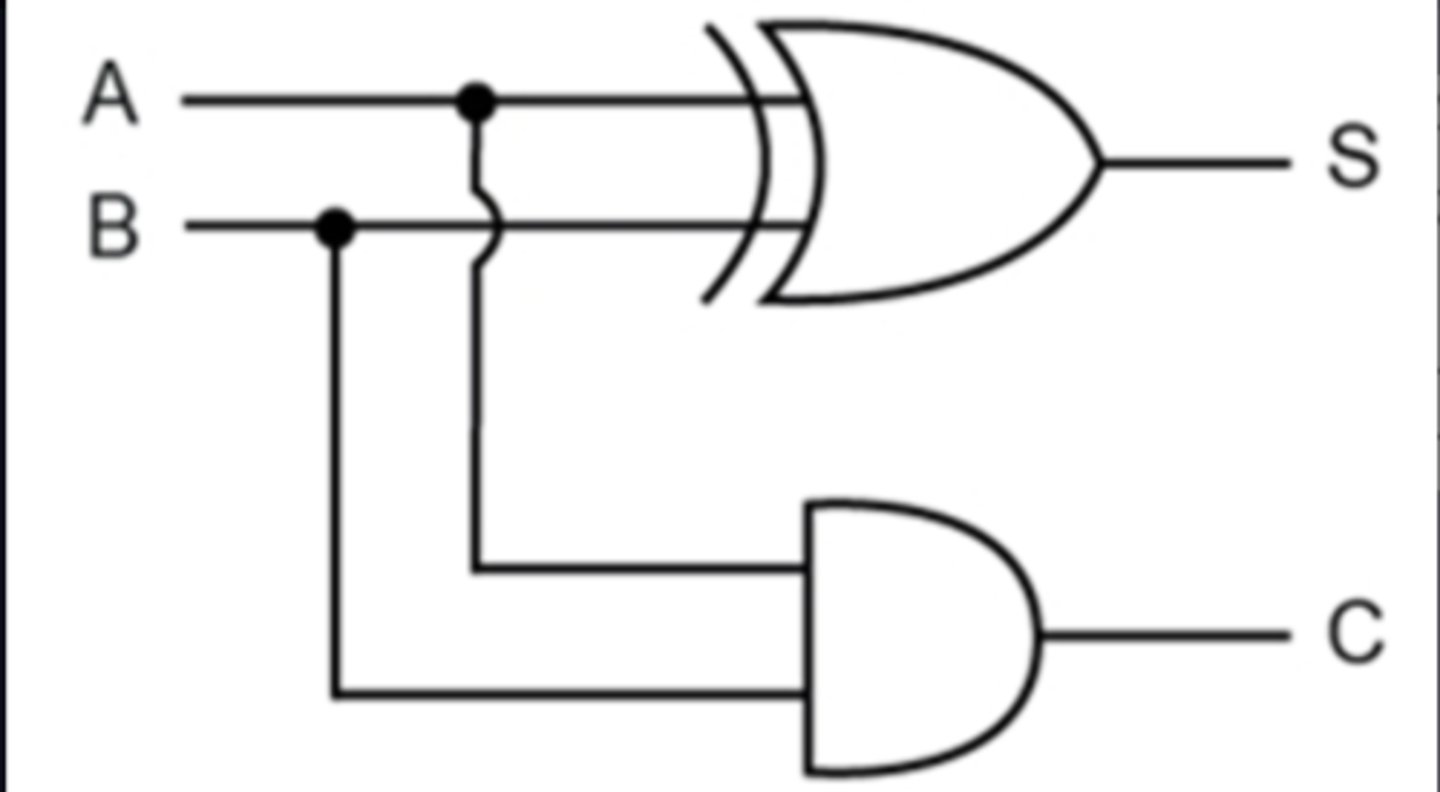
Half-Adder
A logic circuit that computes the sum of two bits and produces the appropriate carry bit.
Inputs - A, B
Outputs - Sum (S), Carry (C)
S = A ⊕ B
C = A · B
Limitations of Half-Adder
Only uses two inputs.
..so cannot use the carry from a previous addition/operation as a third input to a subsequent addition.
Can only add one-bit numbers alone.
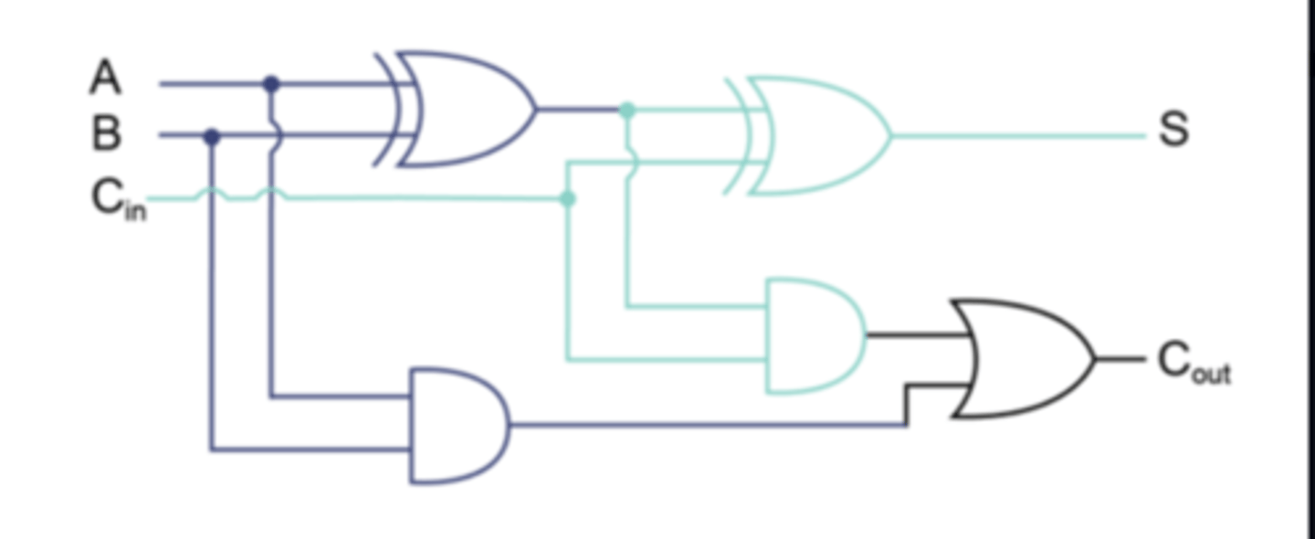
Full Adder
A circuit that computes the sum of two bits, taking an input carry bit into account.
Uses a combination of two half-adders (two half adders combined using an OR/XOR gate).
Inputs - A, B, Cin
Outputs - Sum (S), Carry (Cout)
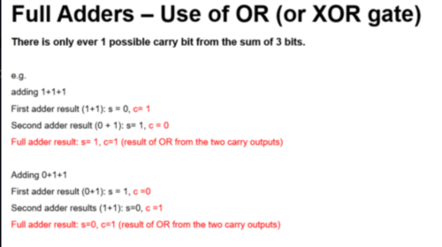
Full Adder use of OR or XOR
The final OR gate before the Cout output may be replaced by an XOR gate without altering the resulting logic.
This is because the only difference between OR and XOR gates occurs only when both inputs are 1. This is never possible with the circuitry of a full adder.
Flip Flop
Circuit / electronic components...
...With two states
Used for data storage...
...to store 1 bit of data
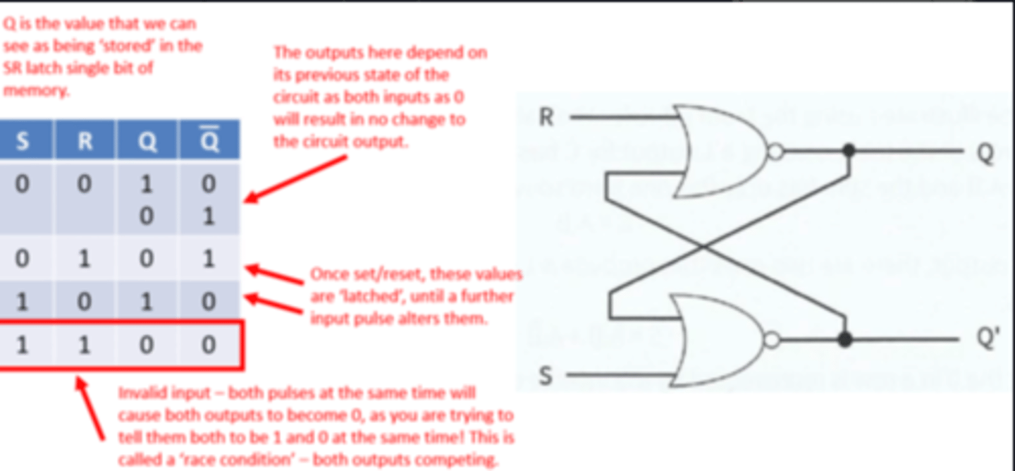
SR Latch (Flip Flop)
Can be constructed with two NAND or two NOR gates.
Maintains (latched) output after the inputs are switched off.
Inputs - S (Set), R (Reset).
Outputs - Q, Q'
Two state device - Either it has Q set to 1 and Q' set to 0 or it has the reverse.
Simple model of how one bit of Static RAM can hold a given value whilst power supplied.
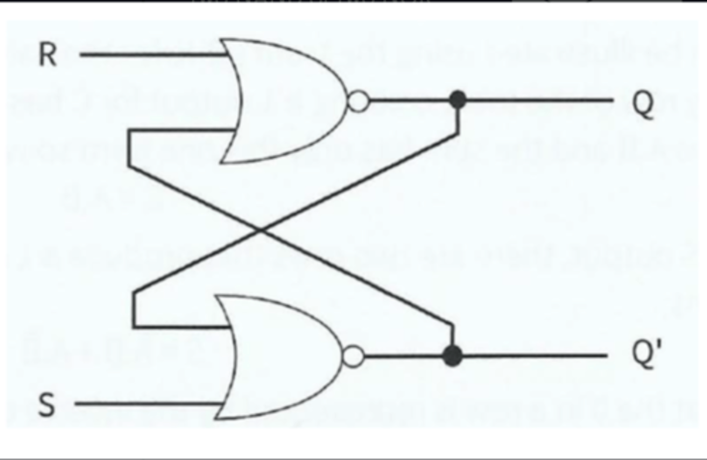
SR Latch - NOR (Active High)
SR Latch - NAND (Active Low)
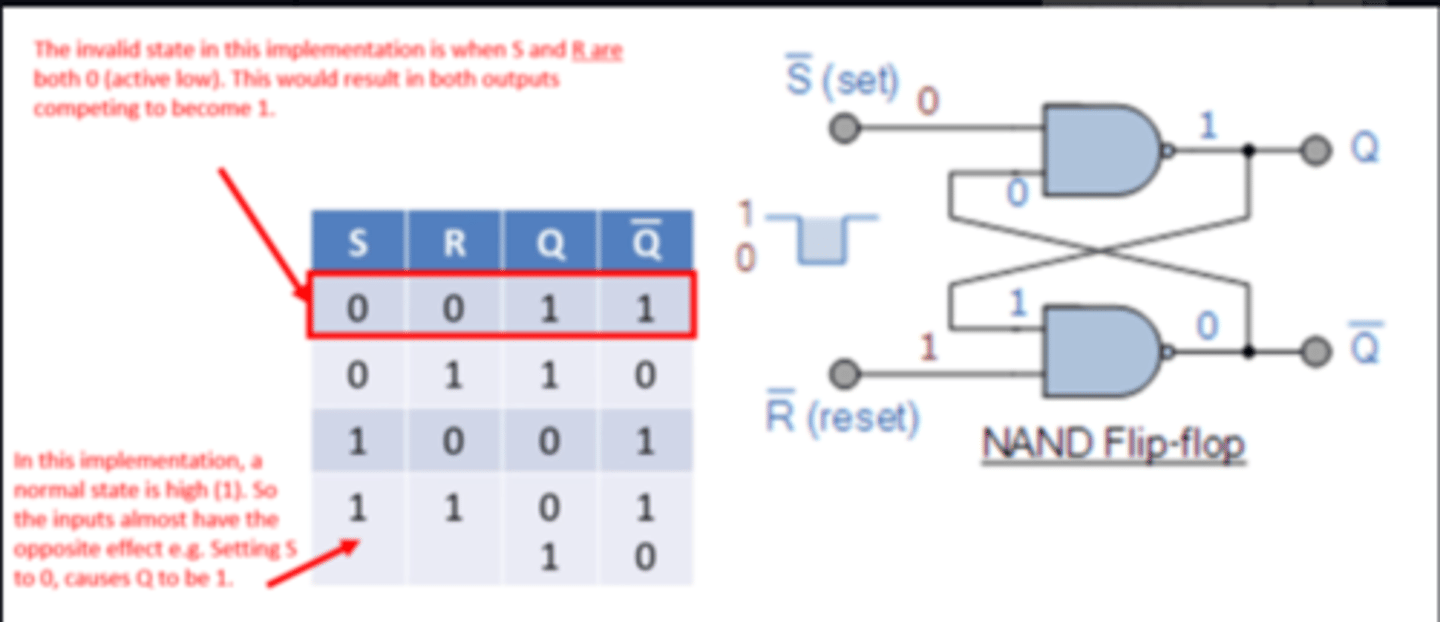
SR Latch Limitations
- Possibility of entering invalid states, if inputs do not arrive at correct time - preventative measures required.
- To prevent this, a clock pulse must be used to synchronise inputs (i.e. a JK flip flop).
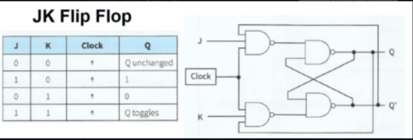
JK Flip Flop
A synchronous/edge triggered version of a SR Latch/flip flop using a clock signal.
The clock is needed to synchronise the changing of states.
Inputs - J (replacing S), K (replacing R), clock
Outputs - Q, Q'
No invalid states - allows both inputs to be 1, which causes a 'toggle' state.
JK Flip-Flop Applications
- Bitwise data storage (e.g. SRAM)
- Data transfer
- Registers storage
Not in mark schemes:
- Binary counters - 'ripple through' counter
- Altering speed of clock/pulse
SR vs JK Flip Flop
SR flip-flop has an invalid state...
...JK flip-flop is always stable
e.g. S = 0 and R = 0 produces Q = 1 and `Q = 1
JK flip flop has a clock pulse
Boolean Algebra Order of Precedence
Brackets first, then:
Highest - NOT
Middle - AND
Lowest - OR
Boolean Algebra Laws
Note: NOT is notated as an overline, but Quizlet does not support this character.
Commutative Law:
A.B = B.A
A+B = B+A
Associative Law
(A.B).C = A.(B.C)
(A+B)+C = A+B+C)
Distributive Law (Expanding/Factorising)
A.(B+C) = A.B + A.C
A+(B.C) = (A+B).(A+C)
Reduction Laws
A + 0 = A
A + 1 = 1
A + A = A
A + NOT(A) = 1
A.1 = A
A.A = A
A. NOT(A) = 0
NOT(NOT(A)) = A
Absorption Laws
A + A.B = A
A.(A+B) = A
Further Redundancy/Absorption
A.(NOT(A) + B) = A.B
A + NOT(A).B = A + B
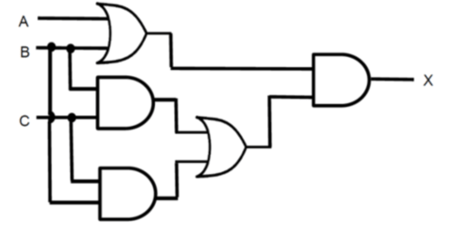
Boolean Algebra Logic Diagram - Worked Example
Boolean Algebra Statement of Logic Diagram and simplification:
Method 1 - Absorption
X = (A.B).(B.C + C.B)
X = (A+B).(B.C + B.C) - Commutative Law
X = (A+B).B.C - Reduction Law
X = C.B.(B+A) - Associative Law
X = C.B (Absorption law)
Method 2 - Long route!
X = (A+B).(B.C + C.B)
X = (A+B).(B.C + B.C) - Commutative Law
X = (A+B).B.C - Reduction Law
X = (B.C.A) + (B.C.B) - Distributive Law (Expanding)
X = (B.C.A) + (B.C) -Reduction Law
X = B.C(A + 1) - Distributive Law (Factorising)
X = B.C.1 - Reduction Law
X = B.C - Reduction
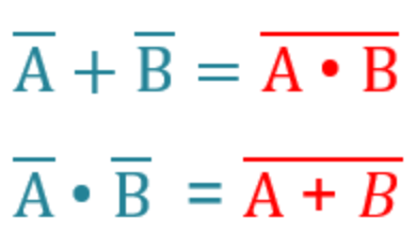
De Morgan's Law
Boolean algebra rule - "Switch the sign, split the line
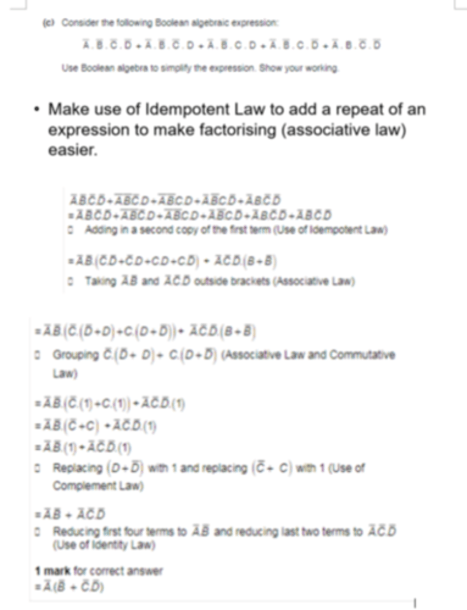
Boolean Algebraic Expression - Worked Example
See attached image.
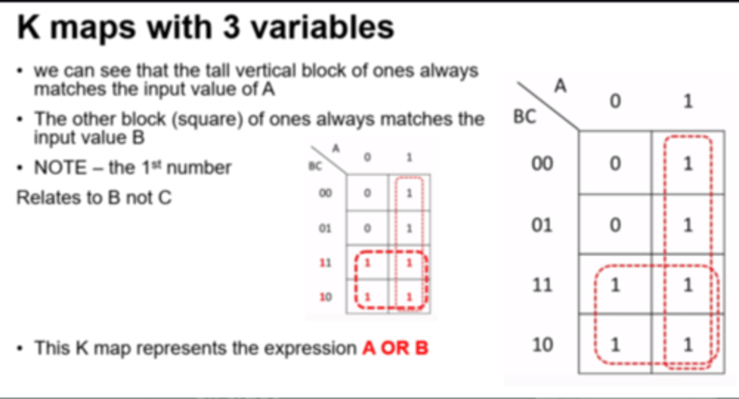
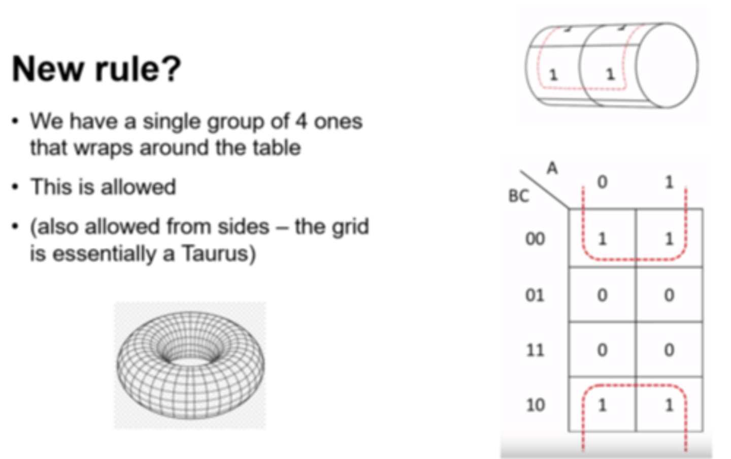
Karnaugh Map
An alternative, graphical way of simplifying logic statements and circuits. See example diagram for layout of binary inputs (example only uses 3 inputs).
Grouping Rules:
- Groups must only contain 1s
- Group must be horizontal or vertical, not diaganal
- A group must contain 2^n 1s (1, 2, 4, 8, etc.)
- Each group should be as large as possible
- Groups may overlap
- Groups may wrap around a table
- Every 1 must be in at least one group
- There should be as few groups as possible
Deriving Expressions:
- Looking at each group will give an expression
- For each group, look for input values that stay constant i.e.
- If an input is always a 1 within the group, then that input will form part of the expression for the group.
- If an input is always a 0 within the group, then the NOT of that input will form part of the expression for the group.
- All constant inputs must be identified to form the expression
- Each of the groups expressions are then joined by OR operators (i.e. creating a sum of products).
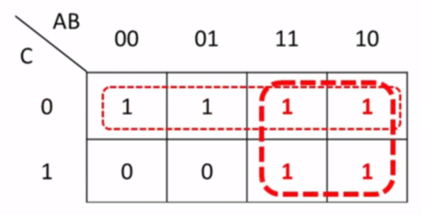
Karnaugh Map Example
- See example attached (3 inputs).
Karnaugh Map - Wrapping
Karnaugh Maps actually act as a Taurus that wraps in on itself - allowed from all sides.
i.e. groups can join into single groups from opposite sides of the grid.
'Sum of Products' Boolean Algebraic Expression
A boolean expression consisting of a number of components with AND operators (products), joined by OR operators (sums).
These can be created from a truth table - each outputted '1' will provide a product statement.
1) Look at the rows with outputted 1s
2) Write down what created that 1 e.g. A.B.NOT C.D
3) Repeat for all 1s
4) Connect with or symbol (+)
Instruction Set
The complete set of all operations/instructions that can be executed/performed by a processor.
Program
The written (static) code to perform an action or task (e.g. part of a piece of software).
It will be allocated a Process Control Block (PCB) to hold all associated data in memory when it is executed (when it becomes a process).
Process
A (dynamic) program/code that is currently executing i.e. it has been assigned a Process Control Block (PCB) in main memory.
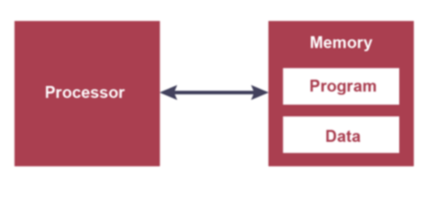
Stored Program Concept
A processor architecture where data and instructions must be held in memory to be executed.
- A program must be resident in (main) memory to be executed.
- A program consists of a sequence of instructions that occupy a block of main memory.
- Instructions and data are indistinguishable
- Each instruction is fetched, decoded and executed by the CPU.
Thread
A single execution sequence within a process that can be split up and executed 'simultaneously'.
Von Neumann Architecture
A processor where data and instructions are held in a common main memory and accessed via a single set of shared buses (same word length).
Used in PCs, laptops, servers.
CISC (Complex Instruction Set Computer)
A type of ISA (Instruction Set Architecture):
- Very large instruction set of complex operations
- More specialised addressing modes
- Fewer general purpose registers within CPU (more use of RAM)
- More complex architecture
- More difficult to program with
- Expensive to manufacture
- Variable length instruction formats (may take longer than a single cycle to be executed - pipelining more difficult)
- Micro-programmed - ROM Chip stores microcode (firmware).
Example multiplication instruction:
MULT A, B
CISC Advantages
- Compiler has very little work to translate high level into low level code
- Very little RAM required to store programs (length of the code is shorter)
- Quicker to produce programs
RISC (Reduced Instruction Set Computer)
A type of ISA (Instruction Set Architecture):
- Small instruction set of simple operations
- Reduced addressing modes to basic set
- More general purpose registers within CPU
- Length of instruction is fixed - pipelining is possible as one instruction read per cycle when possible
- Simpler architecture
- Cheaper to manufacture
- Hard-wired - CPU is constructed as a combination of logic circuits with instructions executed directly by those circuits (no internal ROM or micro-programming).
Example multiplication instruction(s):
LDA R1, A
LDA R2, B
MULT R1, R2
STO R1 A
RISC Advantages
- Simpler hardware as fewer circuits are needed for less operations.
- Pipelining is possible because each instruction is the same length and takes a single cycle to fetch.
- Although code occupies larger amount of RAM - RAM is now fairly cheap and RISC allows better performance processors at smaller costs.
Pipelining
Instruction level parallelism
Execution of an instruction is split into a number of stages...
...When first stage for an instruction is completed the first stage of the next instruction can start executing
Another instruction can start executing before the previous one is finished
Processing of a number of instructions can be concurrent / simultaneous
RISC Pipeline
Usually based around having 5 steps that can be overlaid in sequence to produce the pipeline:
1. Fetch instruction from memory (IF - Instruction Fetch)
2. Read registers and decode (ID - Instruction Decode)
3. Access an operand in memory (OF - Operand Fetch)
4. Execute the instruction (IE - Instruction Execute)
5. Write the result into register (WB - Write back)
Pipelining Problems - Data Dependencies
Occur when an instruction's execution depends on the results of a previous instruction that has not yet been completed e.g. branching.
Pipeline is therefore stalled.
Longer pipelines suffer from this problem more than shorter pipelines.
Pipelining Data Dependency Solution
Code re-ordering - generally left to compiler to recognise data dependencies and re-order code accordingly if possible.
Interrupt
A signal from a software source or hardware device seeking for attention from the processor.
E.g.
- Program errors
- Hardware faults
- I/O processing
- Timer signal (e.g. from low level scheduler)
Interrupt flags are checked at the end of each fetch-decode-execute cycle.
Basic Interrupt Handling Process
1. Processor is executing Process A.
2. Process B raises an interrupt for processor attention (of higher priority).
3. All register contents for Process A are saved on a stack in the Process Control Block for Process A.
4. Appropriate Interrupt Service routine for Process B initiated.
4. CPU begins execution of Process B.
5. Once Process B ends, the contents of the registers for Process A are popped and returned to the CPU so it can continue to execute.
Process Control Block (PCB)
A data structure held in memory used by the OS to store all information about a process that is active .
A PCB is created every time a process is initiated (i.e. copied to RAM).
Interrupt Handling with Pipelining
Interrupt handling is more complicated when pipelining (RISC) - not all instructions in the pipeline are finished when an interrupt may be initiated.
Solutions:
- All instructions other than the oldest/completed are flushed/erased
- Add additional units to the processor with additional program counters so that the full states of the pipeline can be placed on a stack.
Instruction-level Parallelism
Multiple instructions can be 'worked on' at the same time within a single processing unit i.e. pipelining
Processor-Level Parallelism
Multiple processing units/cores can work on multiple instructions simultaneously.
Each unit can work on different parts of one process or different processes entirely.
Usually the units/cores will share the same buses.
Software has to be written to make use of multiple cores e.g. using threading
Computer-Level Parallelism
Large numbers of separate processors working together i.e. networked computer systems working as a unit (Massively Parallel Computers).
Multi-programming/Multi-tasking
A computer running more than one program at a time i.e. making use of scheduling to switch between processes.
Parallel Processor Systems
4 categories:
•Single Instruction Single Data Stream (SISD)
•Single Instruction Multiple Data Stream (SIMD)
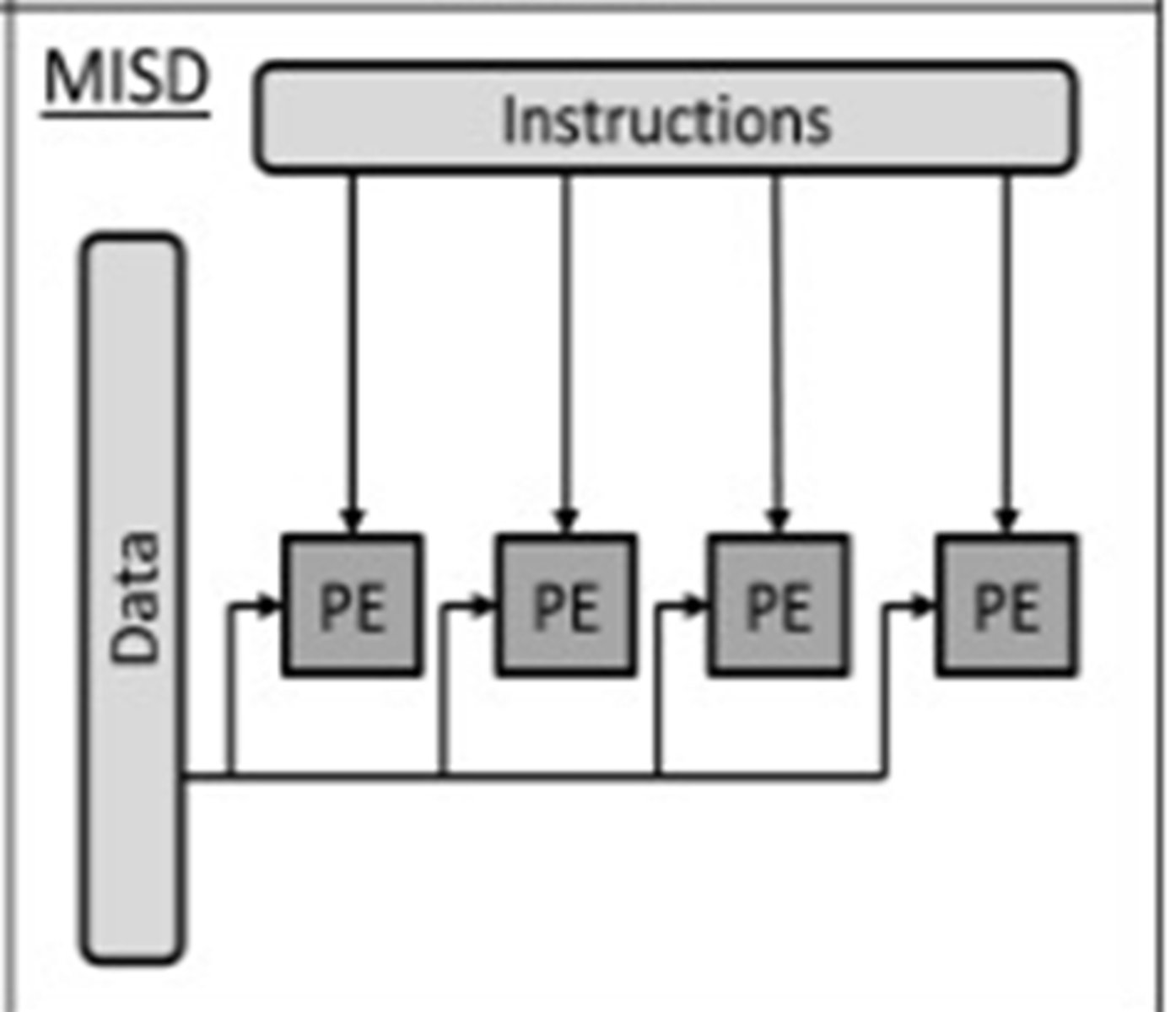
•Multiple Instruction Single Data Stream (MISD)
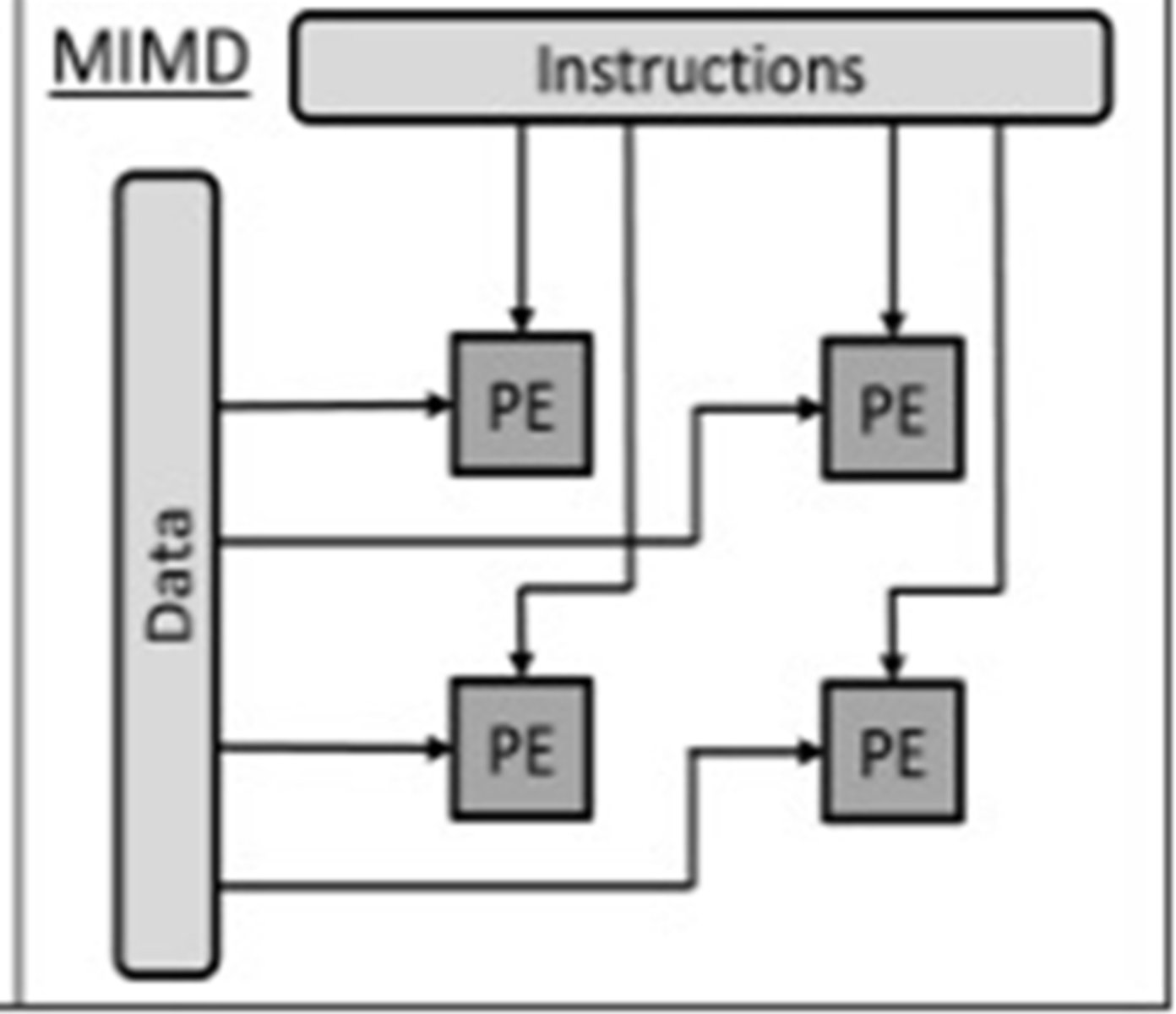
•Multiple Instruction Multiple Data Stream (MIMD)
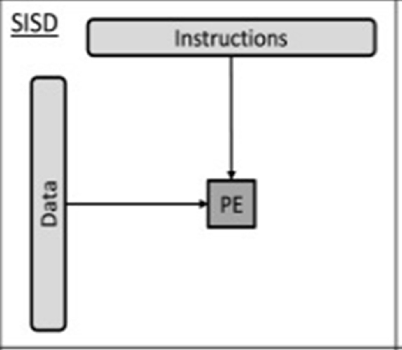
SISD (Single Instruction Single Data Stream)
Single Processor Element/Unit
A computer that does not have the ability for parallel processing
Single processor executing one set of instructions on a single set of data.
E.g. microcontroller for a dishwasher
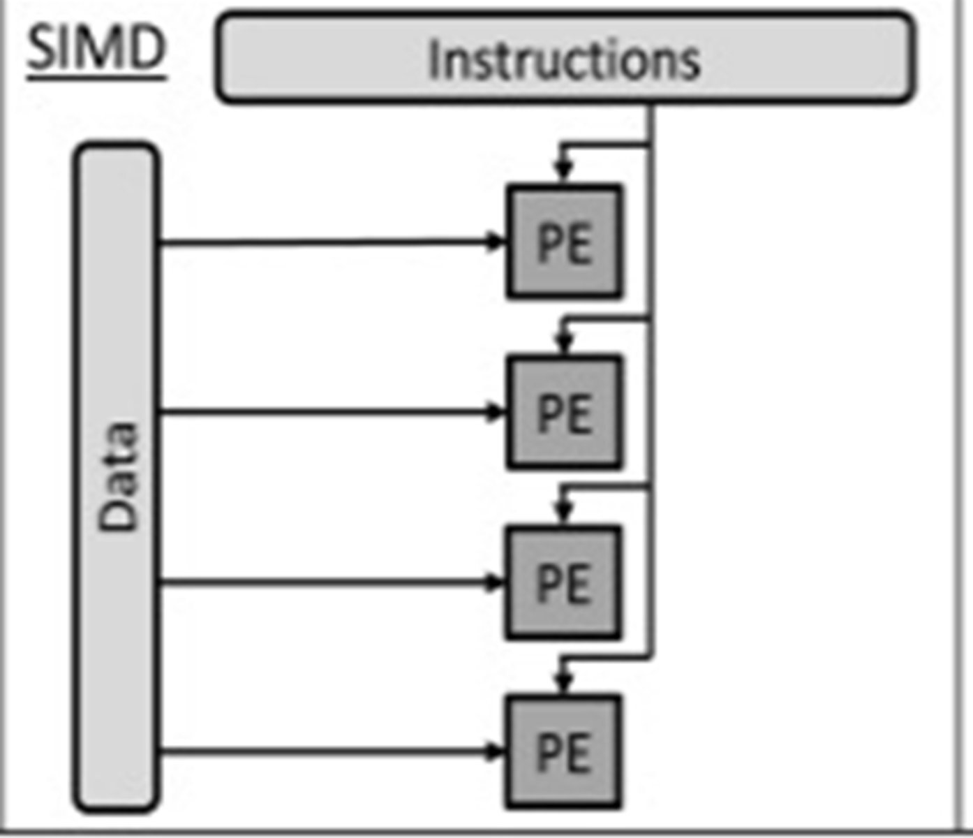
SIMD (Single Instruction Multiple Data Stream)
Multiple processors (each with own ALU and registers)...
... execute single instruction executed using different data
Applicable to manipulating image pixel matrix (e.g. within a GPU) or audio sample data.
MISD (Multiple Instruction Single Data Stream)
Many processors (using different instructions) use the same data set
No real practical use other than fault tolerance
MIMD (Multiple Instruction Multiple Data Stream)
Many processors (using different instructions) using different data sets
Number of processors that function asynchronously and independently.
Different processors may be executing different instructions on different pieces of data
Massively Parallel Computer
Large number of processors
Working collaboratively// co-ordinated simultaneous processing
Communicating via a messaging interface
Makes use of complex network infrastructure
Massive - large number of separate processors// hundreds/thousands of processors.
Parallel - Able to perform co-ordinated processes simultaneously
MPC Software Considerations
Split into blocks of code...
...that can be processed simultaneously
...instead of sequentially
Each block is processed by a different processor...
...which allows each of the many processors to simultaneously process the different blocks of code independently
Requires both parallelism and co-ordination
MPC Hardware Considerations
•Processors need to be able to communicate effectively
•...so that processed data can be transferred from one processor to another.
•Each processor needs link to each other requiring numerous links...
...Many processors require many of these links
Virtual machine
The emulation of a computer system / hardware and/or software...
... using a host computer system.
Using guest operating system(s) for emulation
Virtual Machine Tasks
- Create/delete virtual machine
- Existing hardware made available to guest OS // hardware emulation
- Ensures each virtual machine is protected from actions of another virtual machine
Guest Operating System (VM)
An operating system running in a virtual machine // Controls virtual hardware // OS is being emulated
Guest OS is running under the Host OS software
Host Operating System (VM)
The operating system that is actually controlling the physical hardware // the operating system for the physical machine// the OS running the VM software
Benefits of a Virtual Machine
Multiple guest operating systems / VMs can be used on the same computer
Different instruction set architectures can be emulated on a single computer
Can crash without affecting the host machine or other software
Trying a piece of suspicious software and if it is / has a virus, it will only infect the virtual machine
New system can be tried on different virtual hardware...
...Cost savings due to not needing to purchase extra hardware
Can run legacy applications that are currently incompatible
Drawbacks of a Virtual Machine
Using virtual machine means execution of extra code or might not be as efficient...
...performance degrades
Performance of the guest system cannot be adequately measured
May be affected by any weaknesses of the host machine i.e. if the host doesn't have much available RAM or processor power
Costly and specialist skills needed to maintain / implement / manage.
Virtual Machine Used to Trial new Software
Trial/use alternative replacement software/hardware configurations
Test to identify possible problems with new software/hardware configurations
Much easier to create VM with new configuration than installing new computer system
Provides a safe environment during testing (which does not disrupt the current software configuration)
Virtual Machine used for testing software on different hardware
Software can be tried on different OS using same hardware
No need to purchase / request all sorts of different hardware
Easier to recover if software causes system crash
VM provides protection to other software / host OS from malfunctioning software
Virtual Machine - Example data request from application in VM
Guest OS handles request as if it were running on its own physical machine // guest OS is not aware it is running on a virtual platform
I/O requests are translated by the virtual machine software into instructions executed by host OS
Host OS retrieves the data needed as per request •
Host OS passes the data to the virtual machine software
The virtual machine software passes the data to the guest OS
Guest OS passes the data to the application