L06 - Thrust chamber & chamber wall cooling
1/92
There's no tags or description
Looks like no tags are added yet.
Name | Mastery | Learn | Test | Matching | Spaced |
|---|
No study sessions yet.
93 Terms
What are the main purposes of a thrust chamber?
A (Short): To inject propellants, ensure combustion, generate thrust, and manage control and interfaces.
A (Long):
The thrust chamber is responsible for injecting propellants at defined mass flow rates, ensuring stable combustion, producing hot gas and thrust, transferring it to the structure, controlling start-up/shutdown, and supporting mechanical, electrical, and fluidic interfaces.
Why are sensors integrated into thrust chambers?
A (Short): To monitor pressure, temperature, and vibrations.
A (Long):
Sensors are embedded in thrust chambers to continuously monitor operational conditions like pressure, temperature, and vibrations, ensuring safe and efficient engine performance throughout the mission.
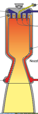
Thrust Chamber Components
Gimbal: Allows the engine to pivot for thrust vectoring.
Injector head: Where fuel and oxidizer are introduced and mixed.
Propellant domes: Hold and direct propellants into injectors.
Injector elements: Spray and atomize fuel and oxidizer.
Combustion chamber (liner): Region where combustion occurs.
Nozzle throat and extension: Accelerate exhaust gases to produce thrust.
Igniter: Initiates combustion (especially for non-hypergolic propellants).
Damping elements: Reduce structural vibrations.
Combustion Chamber Design Goals
Achieve complete combustion of propellants.
Ensure minimal energy losses.
Manage thermal and mechanical loads.
Enable simple and cost-effective manufacturing.
Fit within geometrical constraints of the rocket stage.
Maintain low weight and low manufacturing costs.
Q (Short): What is the primary goal of combustion chamber design?
A (Short): Complete combustion of propellants with minimal losses.
A (Long): The main goal is to ensure full combustion of fuel and oxidizer to maximize efficiency, while minimizing energy losses and maintaining structural integrity, simplicity, and cost-efficiency.
Q (Short): Why is controlling thermal and mechanical loads critical?
A (Short): To ensure chamber durability and safety.
A (Long):
Proper control of thermal and mechanical stresses helps prevent failure due to overheating or material fatigue, ensuring the combustion chamber can survive harsh operational conditions.
Combustion chamber design
Design steps
Shape and dimensioning of the chamber.
Injection element selection based on propellants.
Injector pattern definition for mixing efficiency.
Structural design for strength and pressure.
Thermal design including:
Heat transfer analysis
Cooling channel and wall design
Advanced cooling methods (film, transpiration, coating)
Performance optimization based on:
Specific impulse (Isp)
Lifetime, reliability, cost
Q (Short): What is the purpose of designing cooling channels?
A (Short): To manage heat and prevent structural failure.
A (Long): Cooling channels are designed to handle intense heat loads by removing heat from the chamber walls, helping maintain material integrity and ensuring long operational life.
What are the final goals in chamber design?
A (Short): Optimize performance, reliability, and cost.
A (Long):
The last step in design involves balancing parameters like specific impulse (Isp), engine lifetime, and manufacturing cost to meet mission requirements efficiently.
Combustion chamber design
Chamber geometry
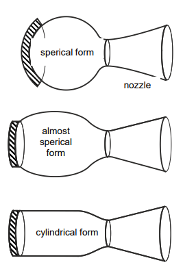
Spherical chambers are
Lowest surface-to-volume ratio
High pressure resistance
Lightweight, efficient cooling
Drawback: Hard to manufacture
Cylindrical chambers
Most common today
Easier to manufacture
Compatible with modular rocket stages
Spherical pre-chambers:
Used in gas generators or pre-burners for high-pressure combustion
Why are spherical chambers rarely used?
A (Short): Because they are hard to manufacture.
A (Long):
Although spherical chambers offer excellent pressure resistance and cooling efficiency due to their low surface-to-volume ratio, their complex geometry makes manufacturing difficult and costly.
What is the most common combustion chamber shape today?
A (Short): Cylindrical cross-section.
A (Long):
Modern combustion chambers typically have a cylindrical shape, as it simplifies manufacturing, integrates well with rocket stages, and still allows effective performance and cooling.
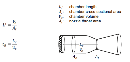
What does the characteristic length L* describe?
A (Short): It compares combustion chamber designs based on volume and throat area.
A (Long):
Characteristic length L∗L^*L∗ is a scaling parameter defined as the chamber volume divided by the throat area, helping compare and design combustion chambers for different propellant types and flow conditions.
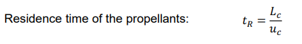
Why is residence time important in chamber design?
A (Short): It ensures complete combustion of propellants.
Crucial for complete combustion and avoiding unburned propellants.
A (Long):
Residence time tR tells how long propellants stay in the combustion chamber. If too short, combustion may be incomplete. Hence, sufficient tR, determined by L*, is vital for performance and efficiency.
Why do different propellants have different L* values?
A (Short): Due to differences in combustion speed and energy release.
A (Long):
Each propellant pair has unique combustion kinetics. Slower-reacting propellants require longer chambers (higher L*) to ensure full combustion before exiting the nozzle.
What determines residence time tR?
A (Short): Characteristic length and flow properties.
A (Long):
Residence time depends on the chamber’s characteristic length and the ratio of chamber to throat density and velocity, defining how long the propellants stay inside the chamber for combustion.
What happens when contraction ratio increases?
A (Short): Throat area decreases, chamber pressure increases, Mach number drops.
A (Long):
Increasing contraction ratio means a smaller throat area compared to chamber area. This raises chamber pressure and reduces the Mach number at the chamber’s end, which is desirable for efficient combustion.
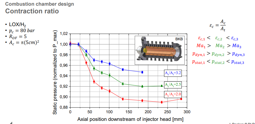
What is the ideal Mach number at the end of the chamber?
A (Short): As low as possible, typically 0.1–0.6.
A (Long):
To minimize energy losses and ensure most pressure is available for thrust, the Mach number at the end of the combustion chamber should be low—ideally under 0.6.
How does higher contraction ratio affect pressure?
A (Short): It slows down pressure drop along the chamber.
A (Long):
With a higher contraction ratio, the nozzle throat is narrower relative to the chamber, causing lower flow velocities and more uniform pressure along the chamber length, which helps maintain combustion stability.
Why is lower Mach number desired in the chamber?
A (Short): To minimize dynamic losses and maintain pressure.
A (Long):
A lower Mach number keeps more of the total pressure available for combustion and expansion, reducing kinetic energy losses and improving combustion efficiency.
Loads in Combustion Chambers
Cryogenic engines face:
Extreme pressures: from vacuum to several hundred bar
Extreme temperatures: 24 K (liquid hydrogen) to 3500 K (hot gases)
What are the three main types of mechanical loads?
A (Short): Stationary, transient, and cyclic loads.
A (Long):
Stationary loads come from thermal gradients and corrosion
transient loads happen during dynamic events like start-up
cyclic loads result from repeated ignition cycles, critical for reusable engines.
Why is hydrogen embrittlement a concern in rocket engines?
A (Short): It weakens metal structure over time.
A (Long):
Hydrogen atoms can diffuse into the chamber material at high temperatures, making the structure brittle and prone to cracking—a serious risk in cryogenic hydrogen-fueled engines.
What’s the peak combustion temperature in LOX/H₂ engines?
A (Short): About 3600 K.
A (Long):
The combustion temperature in LOX/LH₂ engines like Vulcain 2 reaches 3600 K—far beyond what structural metals can withstand—necessitating advanced cooling techniques.
Where is the highest heat flux in a combustion chamber?
A (Short): At the nozzle throat.
A (Long):
The narrowest part of the chamber, the nozzle throat, experiences the highest velocity and heat transfer, leading to thermal fluxes up to 80 MW/m²—requiring critical cooling attention.
What is regenerative cooling?
A (Short): Heat is removed by circulating fuel/oxidizer through chamber walls.
A (Long):
Regenerative cooling uses the engine's propellants to absorb heat via embedded wall channels, cooling the chamber while simultaneously preheating the propellant for combustion.
Name two alternative cooling methods besides regenerative.
A (Short): Film and ablative cooling.
A (Long):
Film cooling forms a protective fluid layer along the inner wall, while ablative cooling relies on gradual material erosion to absorb heat—used in simpler or disposable engines.
what is Low Cycle Fatigue (LCF)?
And events that cause LCF?
Plastic deformation due to cyclic thermal and mechanical loading
Events that cause LCF:
Start-up: cooled to cryogenic temps (~40 K)
Operation: heated to ~800 K
Shutdown: rapid cooling then warming
What causes low cycle fatigue in rocket engines?
A (Short): Repeated temperature swings during start-stop cycles.
A (Long):
Low cycle fatigue arises from thermal expansion/contraction cycles.
cooling to cryogenic temperatures and heating during operation.
leading to cracks, leakage, and structural failure over time.
What’s the dog-house effect?
A (Short): Leak formation due to LCF cracks in cooling channels.
A (Long):
The dog-house effect refers to fatigue-induced structural deformation or cracking in the cooling channels that causes hot gases to leak into walls, accelerating material damage and reducing lifespan.
What is blanching in combustion chambers?
A (Short): Local erosion from cyclic oxidation and reduction.
A (Long):
Blanching is damage caused by varying fuel/oxidizer ratios, creating hot spots and alternating oxidizing/reducing environments. This corrodes surface layers and forms roughness and pores.
What damage does blanching cause?
A (Short): Roughness, pores, and cooling channel leakage risk.
A (Long):
Blanching increases inner wall roughness, weakens surface layers, and may cause cooling channel breaches—affecting efficiency and potentially leading to catastrophic failure if unmanaged.
Hydrogen is present at high pressure and varying temperatures in which components?
And what is the risk on that?
Preburner: up to 300 bar at 800 K
Propellant lines: up to 400 bar at 24 K and 300 bar at 800 K
Main combustion chamber: up to 200 bar at 3600 K
These extreme conditions make hydrogen embrittlement a critical threat throughout the system.
Where does hydrogen embrittlement occur in a staged combustion cycle?
A (Short): Preburner, propellant lines, and combustion chamber.
A (Long):
Hydrogen embrittlement can occur in all hydrogen-carrying components—preburner, lines, and combustion chamber—due to exposure to very high pressures (200–400 bar) and extreme temperatures (24–3600 K).
What causes hydrogen embrittlement?
A (Short): Diffusion and recombination of atomic hydrogen inside metal.
A (Long):
Hydrogen embrittlement occurs when H₂ dissociates into atomic hydrogen, diffuses into metal, and recombines at microstructural flaws, causing cracks due to internal pressure buildup.
At high temperatures, H atoms are more mobile.
Recombination at lattice defects causes Hydrogen-Induced Cracking
Which materials are most affected by H₂ embrittlement?
A (Short): High-strength steels, titanium, and oxygen-rich copper.
A (Long):
Materials like high-strength steels, titanium, and copper with oxygen content are especially vulnerable, as their internal structure promotes diffusion and trapping of hydrogen atoms.
Melting Points of Materials
Melting point determines
Melting point determines thermal resistance of a material.
Which material has the highest melting point?
A (Short): Tungsten.
A (Long):
Tungsten melts above 3600 K, offering unmatched thermal resistance. However, it's rarely used due to poor machinability, high cost, and limited ductility at room temperature.
Why aren’t W or Re used as main chamber materials?
A (Short): Too heavy, costly, and hard to manufacture.
A (Long):
Despite their high melting points, tungsten and rhenium are dense, expensive, and difficult to machine or weld, making them impractical for large combustion chamber structures.
Copper is ideal for combustion chamber walls because its high thermal conductivity (about 400 W/mK). WHY?
Copper is ideal for combustion chamber walls because its high thermal conductivity (about 400 W/mK) enables rapid heat removal, reducing the risk of thermal failure.
How does copper behave thermally?
A (Short): It expands significantly with temperature.
A (Long):
Copper exhibits non-linear thermal expansion that increases rapidly as temperature rises, especially above 150 K—important for combustion chambers exposed to large thermal swings.
Why is copper's thermal expansion important in rocket engines?
A (Short): It causes stress between cold fuel and hot gases.
A (Long):
Copper’s thermal expansion leads to internal stresses when exposed to cryogenic fluids (like LH₂ at ~24 K) and combustion gases (~3000 K), making it crucial in thermal stress management.
What makes CuCrZr suitable for cooling?
A (Short): High and stable thermal conductivity.
A (Long):
CuCrZr maintains excellent thermal conductivity even at low temperatures, making it ideal for combustion chambers that require efficient heat removal in cryogenic environments.
Which materials are used for combustion chambers?
A (Short): Copper alloys, steel, fiber composites, and refractory metals.
A (Long):
Combustion chambers use copper-based materials for heat conduction, steel for MMH/NTO compatibility, and exotic metals like rhenium/iridium/niobium in small or high-performance engines.
What materials are nozzle extensions made of?
A (Short): Steel or fiber composites.
A (Long):
Nozzle extensions often use steel or lightweight fiber composites to withstand thermal loads and reduce structural mass, especially in vacuum-optimized upper stages.
What is NARloy-Z made of?
A (Short): Copper with silver and zirconium.
A (Long):
NARloy-Z is a copper-based alloy containing 3% silver and 0.5% zirconium, providing high strength and thermal conductivity for use in high-performance rocket engines.
Why is NARloy-Z widely used?
A (Short): Good balance of strength and heat transfer.
A (Long):
NARloy-Z offers excellent thermal conductivity like copper but with improved mechanical strength, making it ideal for long-life, regeneratively-cooled combustion chambers.
What’s a key advantage of Cu-Cr-Nb over NARloy-Z?
A (Short): Higher thermal capacity and lower weight.
A (Long):
Cu-Cr-Nb allows for combustion chamber operation at higher thermal loads and offers mass savings, but it requires costly powder metallurgy processes and is more brittle.
What limits the use of Cu-Cr-Nb?
A (Short): Manufacturing difficulty and low ductility.
A (Long):
Because Cu-Cr-Nb can't be cast or forged, large parts must be made using advanced and expensive techniques like vacuum plasma spraying, and it has lower toughness than NARloy-Z.
Can copper alloys be used with NTO/MMH?
A (Short): No, they corrode.
A (Long):
Copper alloys react chemically with nitrogen tetroxide or monomethylhydrazine, causing corrosion. For such propellants, corrosion-resistant materials like nickel or steel are required.
What are the main categories of thrust chamber manufacturing?
A (Short): Integral, shell, alternative, special liner, and 3D printed designs.
A (Long):
Manufacturing methods include integral (galvanic/soldered), shell-based (double shell), alternative (tube/ceramic), and special liner designs. Additive manufacturing (3D printing) is also gaining importance.
What is the integral electroplating design?
A (Short): Combustion liner with electroplated nickel shell.
A (Long):
This method uses a copper liner for thermal performance and coats it with an electroplated nickel layer for strength and durability, common in engines like Vulcain 2.
Integral Electroplating Design (Galvanic)
Advantages:
Disadvantages:
Advantages:
Smooth, customizable internal surfaces
Layer structure tailored to needs
Disadvantages:
Time-consuming plating
Nickel weldability issues
Process parameter control is critical
Why is wax used in galvanic design?
A (Short): To fill cooling channels during plating.
A (Long):
Wax is temporarily placed in cooling channels to prevent them from filling with plating material. After plating, the wax is melted and removed to restore the cooling passages.
What’s the integral soldering method?
Advantages, disadvantages?
A (Short): Liner and cast shell joined by solder.
A (Long):
This design involves a copper liner inserted into a cast outer shell. The two are joined via high-temperature soldering, providing good strength but no repairability.
Disadvantages:
No repair possible
High-temp brazing degrades material
Overall design is heavy
Why is this method considered heavy?
A (Short): High-temp soldering weakens material; thicker shells needed.
A (Long):
Thermal degradation from brazing lowers the material's strength, requiring thicker, heavier shell walls to meet mechanical requirements—especially problematic for upper stages.
What is the double shell design?
Advantages/Disadvantages
A (Short): Copper liner inside two outer welded shells.
A (Long):
The design sandwiches a copper liner between two outer shells. It provides structural support but needs precise welding and thermal stress compensation, making it more complex.
Disadvantages:
Critical weld joints
Needs throat stiffening, adds weight
Must compensate contraction at welds due to cooling
Why is throat stiffening used in Double Shell Design?
A (Short): To prevent deformation under pressure.
A (Long):
Due to thermal and mechanical loads at the narrowest part (the throat), extra reinforcement is needed to avoid failure—this adds weight but ensures structural integrity.
What is the tube design used for?
A (Short): Regenerative cooling.
A (Long):
Tube design uses individual cooling tubes arranged along the combustion chamber or nozzle, allowing efficient heat removal but requiring careful alignment and bonding.
What is a challenge of tube design?
A (Short): Complex manufacturing and inspection.
A (Long):
With hundreds of small tubes to solder and seal, ensuring quality and structural integrity becomes time-consuming and expensive, especially in large engines like Vulcain.
Why is tube design good for expander cycles?
A (Short): It increases heat transfer due to rough surfaces.
A (Long):
The non-smooth inner surface of tubes improves thermal exchange between gas and coolant, making it especially suitable for expander cycle engines where maximum heat pickup is needed.
Why aren’t variable-diameter tubes used often?
A (Short): They’re difficult and expensive to manufacture.
A (Long):
Tubes with varying diameters offer better conformity to complex contours but require precision manufacturing and are cost-prohibitive for large-scale production.
Why is the tube design good for nozzles? Nozzle extension
A (Short): High-pressure tolerance and excellent cooling.
A (Long):
Tube-based cooling in nozzles allows thin walls and efficient heat removal. The individual tubes can handle very high coolant pressures, crucial in regeneratively cooled engines.
What’s a benefit of ceramic materials?
A (Short): High temperature resistance and low weight.
A (Long):
Ceramics like Si₃N₄ or C/SiC can withstand extreme temperatures while remaining lightweight, making them ideal for space applications where weight and heat resistance are critical.
What is the main challenge with ceramic chambers?
A (Short): The metal-ceramic interface.
A (Long):
Joining metal components to ceramic parts is technically difficult due to mismatched thermal expansion and poor bonding strength, often limiting structural integrity or repairability.
How are ceramic nozzles extension cooled?
A (Short): By radiative cooling.
A (Long):
Ceramic nozzle extensions are cooled via radiation since convection cooling isn’t needed in vacuum. Their high emissivity allows efficient thermal radiation into space.
What is the sandwich design method in rocket cooling systems?
Short Answer: Milled channels with laser-welded cover.
Long Answer: The sandwich design involves milling cooling channels into a base plate and sealing them with a laser-welded cover followed by metal deposition. It's easier and cheaper but needs expertise.
sandwich design method
Advantages
Challenges
Advantages:
Easier to fabricate than complex tube structures.
Cheaper in terms of production cost.
Challenges:
Requires advanced technology and experienced workforce.
Why are ribs added to the hot gas side in some combustion chambers?
Short Answer: To increase heat transfer.
Long Answer: Ribs on the hot gas side enhance turbulence and surface area, improving heat exchange between the chamber wall and coolant—beneficial in expander cycle engines.
What could be a challenge for special liner designs?
Short Answer: Increased mechanical complexity and manufacturing difficulty.
Which engine cycle could profit from special liner designs?
Short Answer: Expander cycle.
What is a key advantage of 3D printing in rocket chamber production?
Short Answer: Complex shapes, fast iteration.
Long Answer: 3D printing allows for rapid manufacturing of complex geometries with fewer parts. It is especially useful for small batch designs and short development cycles.
Why is post-treatment necessary in 3D-printed rocket chambers?
Short Answer: Remove powder, seal quality.
Long Answer: Post-treatment ensures that residual powder is removed from cooling channels and that sealing surfaces meet quality standards. This is essential for proper function and safety.
What happens if the chamber is over-cooled?
Short: Efficiency drops due to energy loss.
Long: Overcooling leads to excessive heat extraction, which reduces the gas temperature, lowering thermal efficiency and possibly preventing full combustion.
Q (Short): What are the three main cooling strategies in rocket combustion chambers?
A (Short): Capacitive, heat transfer, and heat/mass transfer.
A (Long): The three main strategies are capacitive cooling (heat stored in material), heat transfer (radiative or regenerative), and heat/mass transfer methods like film, ablative, or transpiration cooling.
What is the main purpose of a Thermal Barrier Coating (TBC)?
A (Short): To reduce the wall temperature.
A (Long): TBCs reduce the temperature of the combustion chamber wall by providing a low thermal conductivity barrier between the hot gases and the metal structure.
Function:
Low thermal conductivity and high temperature resistance
Reduces the wall temperature (T_wall) significantly
Keeps hot gas heat from reaching the metal base
What are two challenges of using TBCs?
A (Short): Thickness control and mechanical stability.
A (Long): Applying TBCs is challenging due to the need for precise control of coating thickness and ensuring mechanical durability under extreme thermal and mechanical stresses inside the combustion chamber.
Capacitive Cooling
Heat is absorbed and stored in the combustion chamber material.
What is the main limitation of capacitive cooling?
A (Short): It can only be used for a few seconds.
A (Long): Capacitive cooling stores heat in the chamber walls, but even with ideal materials, its use is limited to a few seconds due to material heat capacity limits.
How does radiative cooling remove heat?
A (Short): Through thermal emission.
A (Long): Radiative cooling works by emitting heat as infrared radiation from the chamber surface to the surroundings, and is suitable for low heat flux applications.
Where is radiative cooling typically applied?
A (Short): In nozzle extensions and small chambers.
A (Long): Radiative cooling is often used in nozzle extensions or small engines where heat flux is low and high-temperature materials can efficiently radiate heat away.
What is the key mechanism behind ablative cooling?
A (Short): Heat is absorbed by material that burns or evaporates.
A (Long): In ablative cooling, a sacrificial layer absorbs thermal energy and removes it through pyrolysis, melting, and evaporation, protecting the underlying metal wall.
What is advantages and the biggest drawback of ablative cooling?
Advantages: simple and cheap method
A (Short): Geometry of the chamber changes over time.
A (Long): Ablation gradually erodes the combustion chamber wall, especially the throat, changing its geometry and reducing performance due to increased throat area and loss of chamber pressure.
How does film cooling protect the chamber wall?
A (Short): By forming a protective fluid film on the surface.
A (Long): Film cooling involves injecting a cold gas or liquid along the chamber wall, which forms a protective layer that insulates the wall from the high-temperature combustion gases.
What is a limitation of film cooling?
A (Short): Cooling effectiveness drops with run length.
A (Long): As the coolant film travels downstream, it mixes with the hot gas and loses effectiveness, making it less protective near the nozzle exit
What makes transpiration cooling more uniform?
A (Short): It uses many small holes or porous walls.
A (Long): Transpiration cooling injects coolant evenly through microscopic holes or porous material, enabling a consistent temperature drop across the entire surface area.
What’s a risk in transpiration cooling?
A (Short): Boundary layer destruction.
A (Long): If the cooling fluid is injected too forcefully in transpiration cooling, it can disturb or destroy the boundary layer, which actually increases wall heat transfer instead of reducing it.
How does regenerative cooling work?
A (Short): Coolant flows in wall channels, absorbs heat, then burns.
A (Long): Regenerative cooling sends fuel or oxidizer through cooling channels around the chamber walls. It picks up heat and is later injected into the combustion chamber, combining cooling and combustion preparation.
Why is counter-flow cooling used in regenerative systems?
A (Short): To cool the hottest part with the coldest coolant.
A (Long): In counter-flow cooling, coolant flows opposite to gas direction, meaning the throat (hottest part) gets the coldest coolant first, maximizing thermal protection where it's needed most.
What is a major risk of overcooling in regenerative systems?
A (Short): Lower gas temperature, reduced efficiency.
A (Long): Excessive cooling can lower the temperature of combustion gases, decreasing thermal efficiency and reducing thrust. Careful balance is required in design.