technical cockpit, driver restraint system, powertrain,aero, vehicle and driver equipment,autonomous system
1/91
There's no tags or description
Looks like no tags are added yet.
Name | Mastery | Learn | Test | Matching | Spaced | Call with Kai |
|---|
No analytics yet
Send a link to your students to track their progress
92 Terms
The cockpit must provide a free internal cross section sufficient for the template shown on the right in figure 10 to pass from the cockpit opening to a point ….rearwards of the face of the rearmost pedal in an inoperative position.
100mm
Percy (95th percentile male)
the helmet of a 95th percentile male and all of the team’s drivers must :
Be a minimum of 50mm away from the straight line drawn from the top of the main hoop to the top of the front hoop.
• Be a minimum of 50mm away from the straight line drawn from the top of the main hoop to the lower end of the main hoop bracing if the bracing extends rearwards.
• Be no further rearwards than the rear surface of the main hoop if the main hoop bracing extends forwards
The 95th percentile male is represented by a two dimensional figure consisting of
two circles of 200mm diameter and one circle of 300mm
The two 200mm circles are connected by a straight line measuring ….. The 300mm circle is connected by a straight line measuring…. with the upper 200mm circle.
The distance between the center of the circle and the rearmost actuation face of the pedals must be minimum….
490mm
280mm
915mm
If there is any chassis member alongside the driver at the height of the neck of any of the drivers in the team
a metal tube or piece of sheet metal must be attached to the chassis to prevent the driver’s shoulders from passing under that chassis member
Any harness attachment to a monocoque must be using one…..‘bolt or two…… bolts and steel backing plates with a minimum thickness of ...
10mm metric grade 8.8
8mm metric grade 8.8
2mm
It must be proven that the attachments for shoulder and lap belts can support a load of …..and the attachment points of the anti-submarine belts can support a load of….
13kN
6.5kN
If the lap belts and anti-submarine belts are attached less than ….apart, these must support a total load of…
100mm
19.5kN
If the belts are attached to a laminated structure or the mounting brackets and tabs are not made from steel at least ……., physical testing is required.
1.6mm thick
Adequate heat insulation must be provided to ensure that the driver is not able to contact any parts of the vehicle with a surface temperature above
60◦C
three types of heat transfer
Conduction insulation by:
No direct contact
a heat resistant, conduction insulation material with a minimum thickness of….
Convection insulation by a minimum air gap of….
Radiation insulation by:
A solid metal heat shield with a minimum thickness of….
reflective foil or tape
8mm
25mm
0.4mm
The firewall must cover any straight line between the parts and any part of the tallest driver below a plane … above the bottom of the helmet.
100mm
Multiple panels may be used to form the firewall but must overlap at least
5mm
Seated in a normal driving position, the driver must have a minimum field of vision of … to either side.
100◦
All drivers must be able to exit to the side of the vehicle in less than ….with the driver in the fully seated position, hands in the driving position on the connected steering wheel wearing the required driver equipment
5s
6-point system
consists of a two-piece lap belt (minimum width 50mm), two shoulder straps (minimum width 75mm) and two leg or anti-submarine straps (minimum width 50mm)
upright driving position
position with a seat back angled at 30◦ or less from the vertical
reclined driving position
position with a seat back angled at more than 30◦ from the vertical
With an “upright driving position”, in side view the lap belt must be at an angle of
between 45◦ and 65◦ to the horizontal.
With a “reclined driving position”, in side view the lap belt must be between an angle of .
60◦ and 80◦ to the horizontal
In “upright driving position” the centerline of the lap belt at the seat bottom should …..forward of the seat back to seat bottom junction
be between 0mm to 76mm
The shoulder harness mounting points must be between …. and …..apart, measured center to center.
180mm
230mm
From the driver’s shoulders rearwards to the mounting point or structural guide, the shoulder harness must be between … above the horizontal and …. below the horizontal
10 moires
20 moires
A head restraint must be provided on the vehicle to limit the rearward motion of the driver’s head and must be padded with an energy absorbing material with a minimum thickness of
40mm
A head restraint must include a rectangular area of at least a minimum width and height of
150mm
The head restraint is no more than ….away from the back of the driver’s helmet
25mm
The contact point of the back of the driver’s helmet on the head restraint is no less than….. from any edge of the head restraint
50mm
The head restraint and its mounting must withstand a force of …applied in the rearward direction at any point on its surface
890N
Any portion of the roll bar, roll bar bracing or chassis which might be contacted by the driver’s helmet must be covered with a minimum thickness of…..
12mm of padding
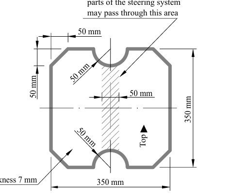
All moving suspension and steering system components and other sharp edges inside the cockpit between the front hoop and a vertical plane …..rearward of the pedals, must be shielded with solid material
100mm
The brake pedal, including the load transfering pedal face and its mounting, must be designed to withstand a force of …..without any failure of the brake system or pedal box
2kN
The brake pedal, including pedal face, must be fabricated from…… or machined from…..
steel or aluminium
steel, aluminium or titanium
The vehicle must be equipped with one brake light that is illuminated if and only if
the hydraulic brake system is actuated
The brake light must
• be a red light. • be clearly visible from the rear.
Cooling systems using plain water must have a heat resistant rigid and rigidly mounted cover which covers any part of the tallest driver below a plane…. above the bottom of the helmet
100mm
Separate catch cans must be employed to retain fluids other than plain water from any vents of the cooling system or combustion engine lubrication system. Each catch-can must have a minimum volume of….
10% of the fluid being contained or 900mL whichever is greater.
Any vent for systems containing plain water must have a catch-can with a minimum volume of….
10% of the fluid being contained or 100mL, whichever is greater.
All parts of the engine, motor(s) cooling and lubrication system, including their mountings, must be rated for at least ( temperature)
100◦C or the temperatures the respective fluid may reach, whichever is higher
Any catch can must vent through a hose with a minimum internal diameter of …..down to the bottom level of the chassis and must exit outside the bodywork.
3mm
Exposed rotating final drivetrain parts, such as gears, clutches, chains and belts must be fitted with scatter shields. Scatter shields and their mountings must Be constructed of non-perforated ….steel or ….aluminium alloy
Be attached with…. bolt
2mm
3mm
6mm metric grade 8.8
Finger guards are required to cover any parts that spin while the vehicle is stationary. Finger guards may be made of lighter material, sufficient to resist finger forces. Mesh or perforated material may be used but must prevent the passage of a …..diameter object through the guard
12mm
All aerodynamic devices forward of a vertical plane through the rearmost portion of the front face of the driver head restraint support must be lower than ….from the ground
500mm
All aerodynamic devices in front of the front axle and extending further outboard than the most inboard point of the front tire/wheel must be lower than …. from the ground
250mm
All aerodynamic devices rearward of a vertical plane through the rearmost portion of the front face of the driver head restraint support must be lower than…. from the ground
1.1m
All aerodynamic devices lower than 500mm from the ground and further rearward than the front axle, must not be wider than
a vertical plane touching the most outboard point of the front and rear wheel/tire
All aerodynamic devices higher than 500mm from the ground, must not extend
outboard of the most inboard point of the rear wheel/tire
All aerodynamic devices must not extend further rearward than ….from the rearmost part of the rear tires
250mm
All aerodynamic devices must not extend further forward than ….from the fronts of the front tires
700mm
Any aerodynamic device must be able to withstand a force of ….distributed over a minimum surface of…. and not deflect more than ….in the load carrying direction
200N
225cm2
10mm
Any aerodynamic device must be able to withstand a force of….applied in any direction at any point and not deflect more than….
50N
25mm
The working gas of any CGS(Compressed Gas Systems) must be
air or pure nitrogen (N2)
The maximum possible operating pressure inside any CGS must not exceed
10bar
The driver and anyone standing outside the vehicle must be shielded from all parts of any HPHS (High Pressure Hydraulic Systems) with an operating pressure of
2100kPa or higher.
Any bolted joint in the primary structure and mounting of the TSAC to the chassis using either tabs or brackets, must have an edge distance ratio “e/D” of …..or greater. “D” equals… and “e” equals….. of the tab or bracket.
1.5
the hole diameter
the distance from the hole centerline to the nearest free edge
]The maximum allowed voltage for motor controller/inverters internal low power control signals is
75VDC
Master switches must be a mechanical switch of the rotary type, with a red, removable handle. The handle must have a width of at least
50mm
The center of any master switch must not be mounted lower than the vertical distance of the template’s middle circle center to the ground surface…
multiplied by 0.8.
The LVMS must be mounted in the middle of a completely red circular area of …..diameter placed on a high contrast background. The LVMSmust be marked with …and a symbol showing …..
≥50mm
“LV”
a red spark in a white edged blue triangle
The minimum allowed diameter of the shutdown buttons on both sides of the vehicle is
40mm
One shutdown button serves as a cockpit-mounted shutdown button and must Have a minimum diameter of
24mm
To detect hard braking, a brake system pressure sensor must be used. The threshold must be chosen such that there are no locked wheels and the brake pressure is….
≤30bar
vehicle number:Height
At least 150mm high
vehicle number: font
Roman Sans-Serif characters
vehicle number :Stroke width and spacing between numbers
At least 20mm
vehicle number: Color
Either white numbers on a black background or black numbers on a white background
vehicle number :Background shape:…. . There must be at least ….between the edge of the numbers and the edge of the background.
round, oval, square or rectangular
25mm
Hybrid Vehicle Identification
“HY” in Roman Sans-Serif characters at least 75mm high in white on a red background
The university name must be displayed and written in ….characters that are at least…. on both sides of the vehicle. It must be horizontally aligned in the middle of the cockpit opening and the top must not be more than …..the lowest point of the cockpit opening.
Roman Sans-Serif
50mm tall
50mm below
Push Bar
must be …. color
a removable devic that attaches to the rear of the vehicle and allows two people to push and pull the vehicle while standing erect behind the vehicle.
red
The …..must be written on the push bar and on the jacks
university name
jacks
Each team must have one or two removable devices that hold the vehicle, so that all driven wheels are at least 100mm off the ground.
On both sides of the vehicle the devices pickup points must be indicated by….
orange triangles
driver equipment
well fitting, unmodified closed helmet
frontal head restrain(?)
balaclava
fire resistant one piece suit, underwear,socks, shoes , gloves
arm restraints
Whenthe remote emergency stop button is pressed
it must open the SDC
Whenthe “Go” button is pressed
the preselected autonomous mission is started.
The SDC may only be closed by the AS, if the following conditions are fulfilled:
• Manual Driving:….
• Autonomous Driving:….
Manual Mission is selected, the AS has checked that ASB is deactivated no autonomous brake actuation possible
Autonomous Mission is selected, ASMS is switched on and sufficient brake pressure is built up,brakes are closed.
The ASMS must be mounted in the middle of a completely …… placed on a high contrast background. The ASMS must be marked with ….
blue circular area of ≥50mm diameter
“AS”
When the ASMS is in “Off” position
No steering, braking and propulsion actuation can be performed by request of the autonomous system
The sensors and the processing units can stay operational
The vehicle must be able to be pushed
It must be possible to operate the vehicle manually as a normal CV
While the ASMS is switched to the “On” position
no person may be (seated) inside the vehicle
no other manual steps other than activating the TS may be performed at the vehicle
Steering system actuation, i.e. movement, must only happen if
the vehicle is in R2D mode or during “AS Emergency”
In autonomous mode, R2D mode may only be entered by the “Go” signal from the RES, after
the system has remained in “AS Ready” for at least 5s.
In autonomous mode, the vehicle must not start moving, until the system
has remained in “AS Driving” for at least 3s

AS off indicator
off
AS ready
yellow continuous
AS driving
yellow flashing
AS emergency
blue flashing and has to be indicated by an intermittent sound
• on-/off-frequency: 1Hz to 5Hz
• duty cycle 50%
• sound level between 80dBA and 90dBA
• duration between 8s and 10s
AS finished
blue continuous
During “AS Driving” and “AS Emergency” the ASSIs must be flashing continuously with a frequency between
2 Hz and 5 Hz
One ASSI must be located on each side of the vehicle behind the driver’s compartment, in a region ….. The third ASSI must be located at the rear of the vehicle, on the vehicle centerline, in a region ….
160mm below the top of the main hoop and 600mm above the ground
160mm below the top of the main hoop and 100mm above the brake light.
The entire surface of at least one ASSI must be visible from any angle of the vehicle from a point …..vertically from ground level, within…. horizontal radius from the top of the main hoop
1.60m
3m
The system reaction time, i.e. the time between opening of the SDC and the start of the deceleration, must not exceed….
200ms
The average deceleration must be greater than …. under dry track conditions
10m/s2