1725 Scatter Radiation
1/55
There's no tags or description
Looks like no tags are added yet.
Name | Mastery | Learn | Test | Matching | Spaced | Call with Kai |
|---|
No analytics yet
Send a link to your students to track their progress
56 Terms
The four x-ray paths
X-rays interact with patient and scatter away from the receptor
X-rays interact and are absorbed (Photoelectric Absorption) within patient
X-rays are transmitted through patient without interaction and strike receptor
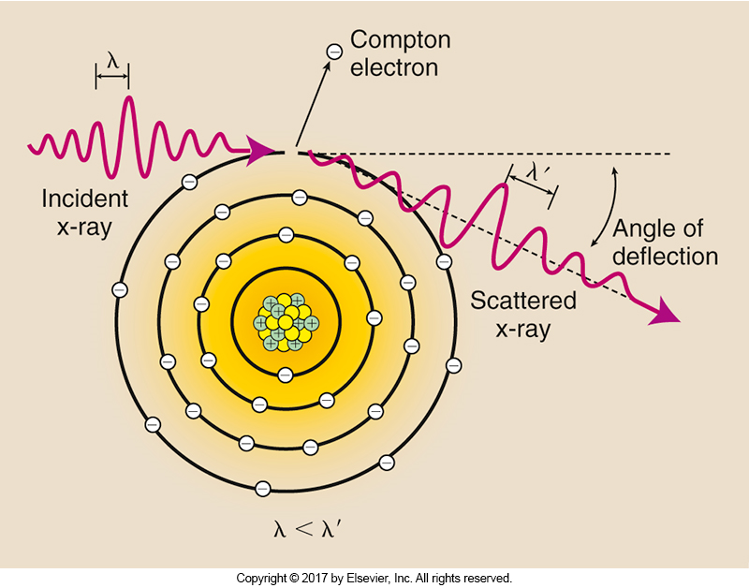
X-rays interact with patient (Compton Scatter) and scatter toward the receptor
Compton Scatter
X-Radiation produces noise, reducing image contrast and contrast resolution. Makes image less visible
What is Scatter Radiation
Scatter exit radiation (Compton interactions) that reaches the image receptor does not provide any diagnostic information about the anatomic area
Scatter radiation creates unwanted exposure on the image called fog (noise) without adding any patient information
Scatter radiation decreases radiographic contrast
Three factors that contribute to increased scatter production
Increased kVp
Increased x-ray field size
Increased patient thickness
Two principal tools used to control scatter
Beam-restricting devices (Collimator Box)
Grids (Controls scatter after it leaves patient and before it gets to IR)
Increasing the volume of tissue irradiated results in increased scatter production
Patient thickness
Increased thickness will increase the volume of tissue irradiated
X-ray beam filed size
Increased field size will increase the volume of tissue irradiated
How does higher kVp affect scatter radiation
It increases the energy of scatter radiation exiting the patient
How kVp affects scatter
As x-ray energy increases, absolute number of Compton Interaction decrease; because using a higher kVp increases x-ray transmission
But the number of photoelectric interactions decreases much more rapidly; reducing Overall absorption
Thus, relative number of x-ray that undergo Compton scattering increase; Therefore increased using higher kVp results in scatter reaching the IR
The amount and energy of scatter radiation exiting the patient depends on the kVP selected
Exams using higher kVp produce a greater proportion of higher energy scattered x-rays
Field Size
As field size increases, scatter radiation increases
Large field size allow greater amounts of exposed tissue to generate scatter radiation
It also decreases contrast
Patient Thickness
Imaging thick parts of the body results in more scatter radiation
With increasing patient thickness, more x-rays undergo multiple scattering
Types of tissue (muscle, fat, bone) and pathology play a role in production of scatter
Compression devices reduce patient thickness and brings the object closer to the image receptor
Compression reduces patient radiation dose, and improves contrast resolution
Ex: Mammography
Why do we want to control scatter radiation
To improve contrast
Loss of contrast results from presence of scattered x-rays
Image formation consists of both transmitted and scattered x-rays
Also for radiation protection (Not the key reason)
Control of Scatter; Beam Restriction/Field Size Limitation
Responsibility of radiographer
As beam restriction increases, field size and patient dose decrease
Serves two purposes: Limiting patient exposure and reducing the amount of scatter radiation, thus preserving contrast
The term beam restriction, field size limitation, and collimation are often used interchangeably
Decrease in the size of the projection radiation field
Types of Beam Restrictors
Aperture Diaphragm
Cones or Cylinders
Variable Aperture Collimator
Aperture Diaphragm
Simplest form of beam restrictor
Flat piece of lead (Diaphragm) that contains a hole (aperture) in the center
Easy to use; placed directly below the x-ray tube window
No widespread use
Cones or Cylinders
Simply an aperture diaphragm that has an extended flange attached
Considered modifications of the aperture diaphragm
Slide onto the tube directly below the window
The position and size of the distal end act as an aperture and determine field size
Useful beam produced is circular
Used to be used for headwork, seen in dentist offices
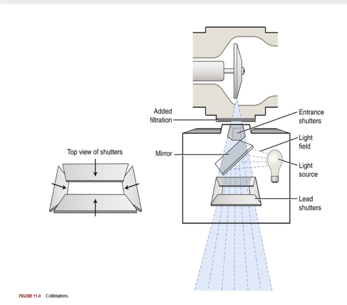
Variable Aperture Collimator
Most commonly used
Located immediately below window
2 or 3 sets of lead shutters
1st stage entrance shuttering device
Located below the tube
Longitudinal and lateral blades
2nd stage collimator shutter
Light localization
Collimator lamp and mirror
Field shape; rectangular or square
Positive Beam Limiting (PBL) Devices
Also called automatic collimators
Automatically limits the size and shape of the IR
Mechanically adjust the primary beam size and shape to the IR
X-ray beam is restricted to the image receptor in use
Previously required by US federal law
Served as a way to protect patients from overexposure
Regulation removed in 1994
Even with PBL, technologists should manually collimate more tightly to reduce patient radiation dose, and improve image quality
Under no circumstances should the x-ray beam exceed the size of the IR
Increased Collimation Results in
Field size decreases
Patient dose decreases
Scatter radiation decreases
Radiographic contrast increases
Increased Field Size Results In
Patient dose increases
Scatter radiation increases
Radiographic contrast decreases
Control of Scatter; Grids
Invented in 1913 by Gustave Bucky and continues to be the most effective means for limiting the amount of scatter radiation that reaches the IR
A device that has very thin lead strips with radiolucent interspaces; it is intended to absorb scatter radiation emitted from the patient
Places between the patient and the IR
Not a radiation protection device because it’s after that patient
Disadvantages of grids
They work well to improve radiographic contrast but are not without drawbacks
Using a grid requires additional mAs, resulting in a higher patient dose
Therefore grids are typically used only when the anatomic part is 10cm (4 inches) or greater in thickness, and more than 60 kVp is needed for the examination
Grid Construction
Radiolucent interspace material separates the lead lines
Interspace material typically is made of aluminum or plastic fibers
The lead lines and interspace material of the grid are covered by an aluminum front and back panel
Grid construction is described by grid frequency and grid ratio
Grids contain thin lead strips or lines that have a precise
Height
Thickness
Space between them
Grid Ratio
The ratio of the height of the lead strips to the distance between them
Grid ratio = h/D
Range of grid ratios
5:1 to 16:1
High-Ratio Grids
More effective in reducing scatter
Increase radiographic contrast
Increase patient radiation dose
As Grid Ratio Increases
Scatter cleanup is more effective and radiographic contrast increases
Patient Dose increases
Likelihood of grid cutoff increases
Grid ratio decreases
Scatter cleanup is less effective and radiographic contrast decreases
Grid Frequency
The number of grid strips per centimeter or inch
Directly related to grid ratio
Higher frequency grids have thinner lead strips
Can range in value from 25 - 80 lines/cm (60-200 lines/inch)
A typical value for grid frequency might be 40 lines/cm or 100 lines/inch
Grid Performance
The purpose of using grids in radiography is to increase radiographic contrast
In addition to improving contrast by cleaning up scatter, grids reduce the total amount of x-rays reaching the IR
The better the grid is at absorbing scattered photons, such as with a higher ratio grid, the fewer the photons reach the IR
To compensate for fewer photons reaching the IR, additional mAs must be used to produce diagnostic images
Grid Conversion Factos (GCF) or Bucky Factor
Can be used to determine the adjustment in mAs needed when changing from using a grid to non-grid (or vice-versa) or for changing to grids with different grid ratios
Mathematical expression of GCF
GCF = mAs with the grid/mAs without the grid
When a grid is added to the IR, mAs must be increased by the factor indicated to maintain the same number of x-ray photons reaching the IR
This requires multiplication by the GCF for the particular grid ratio
mAs multiplication factor Non-Grid
1
mAs multiplication factor 5:1 grid ratio
2
mAs multiplication factor 6:1 grid ratio
3
mAs multiplication factor 8:1 grid ratio
4
mAs multiplication factor 10:1/12:1 grid ratio
5
mAs multiplication factor 16:1 grid ratio
6
Grid Conversion Formula
mAs1/mAs2 = conversion factor1/conversion factor2
Information about a grid’s construction is contained on a label places on the tube side of the grid. The label usually states:
The type of interspace material used
Grid frequency
Grid ratio
Grid size
Information about the range of SIDs that can be used with the grid
Grid Pattern
Refers to the linear pattern of the lead lines of a grid
Two types of grid pattern exist:
Linear
Crossed or cross-hatched
Linear Grid Pattern
A linear grid has lead lines that run in only one direction
Most popular because they allow angulation of the x-ray tube along the length of the lead lines
Cross or Cross-Hatched Grid Pattern
Lead lines that run at right angles to one another
Remove more scattered photons than linear grids because they contain more lead strips that are oriented in two directions
Disadvantage
Applications are limited with a crossed grid because the x-ray tube cannot be angled in any direction without producing grid cutoff (absorption of the transmitted x-rays)
Have limited applications in radiography
Grid Types
The orientation of the lead lines to ones another
Two types of grid focus exist:
Parallel (nonfocused)
Focused (Matches the divergence of the x-ray beam)
Parallel Grid or nonfocused grid
Has lead and interspace strips that run parallel to one another
Never intersect
Less commonly used because the strips do not coincide with beam divergence
Focused Grid
Has lead lines that are angled, or canted, to approximately match the angle of divergence of the primary beam
The advantage of focused grids compared with parallel grids is that focused grids allow more transmitted photons to reach the IR
If the lead strips in a focused grid were extended, the strips would intersect at a convergence line at the convergent point
Convergence line is an imaginary line
Focused Grid Focal Distance
Sometimes referred to as grid radius
The distance between the grid and the convergent line or point
The focal distance is important because it is used to determine the focal range of a focused grid
The focal range is the recommended range of SIDs that can be used with a focused grid
Ex: a common focal range is 36-42 inches, with a focal distance of 40 inches. Another common focal range is 66-74 inches, with a focal distance of 72 inches
Stationary Grids
When grids are stationary, it is possible to closely examine and see the grid lines on the radiographic image
Reciprocating Grids
Slightly moving the grid during the x-ray exposure blurs the grid lines
Reciprocating grids are part of the Bucky, more accurately called the Potter-Bucky diaphragm
The grid is located directly below the radiographic tabletop, and just above the tray that holds the IR
Grid motion is controlled electrically by the x-ray exposure switch
The grid moves slightly back and forth in a lateral direction over the IR during the entire exposure
Grid Cutoff
A decrease in the number of transmitted photons that reach the IR because of some misalignment of the grid
Undesirable absorption of primary x-rays by the grid
The primary radiographic effect of grid cutoff is a further reduction in the number of photons reaching the IR, resulting in a decrease in radiographic density for a film image or increase in noise caused by a decrease in x-ray photons reaching the digital IR
May require that the radiographer repeat the image, thereby increasing patient dose yet again
Grid ratio has a significant effect on grid cutoff, with higher grid ratios resulting in more potential cutoff
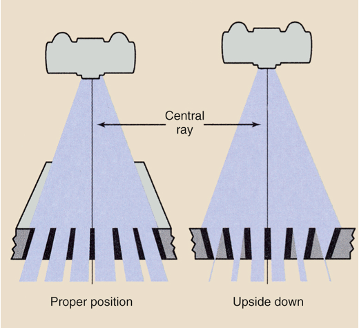
Types of Error in Grid Use - Upside Down Grid
Occurs when a focused grid is placed upside down on the IR, resulting in the grid lines going opposite the angle of divergence of the x-ray beam
Causes the lateral edges of the IR to be highly under exposed
Is easily avoided because every focused grid should have a label indicating “tube side”
This side of the grid should always face the tube, away from the IR
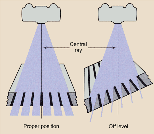
Grid Problems Off - Level Grid
Grid cutoff across image; underexposed, light image
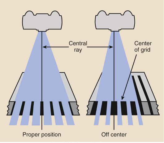
Grid Problems Off Center Grid
Grid cutoff across image, underexposed, light image. Dark on one side of the image and light on the other
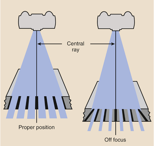
Grid Problems Off Focus Grid
Grid cutoff more severe at edges. Symmetrical grid cutoff, loss of exposure toward lateral edges of image
Moire Effect
Also known as zebra pattern, is an artifact that can occur when a stationary grid is used during CR imaging.
If the grid frequency is similar to the laser scanning frequency during CR image processing, then a zebra pattern can result on the digital image
Use of a higher grid frequency or a moving grid with CR digital imaging eliminates this type of grid error

Air Gap Technique
Alternative technique to the use of radiographic grids
Reduces scatter radiation, enhancing image contrast
Simple concept: Most scatter will miss the IR if there is increased OID
The greater the gap, the greater the reduction in scatter reaching the IR
The mAs is increased approximately 10% for every centimeter of air gap