Energy Resources
1/13
Earn XP
Description and Tags
Contains only sections 4 & 5, as these are the ones coming up on the exam
Name | Mastery | Learn | Test | Matching | Spaced | Call with Kai |
|---|
No analytics yet
Send a link to your students to track their progress
14 Terms
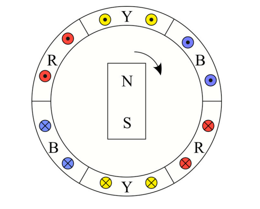
Three-phase generators
When three separate supply lines, from three-phase generators, are used to deliver power to “components”
Line voltage (VL)
The potential difference between any two supply lines
Phase Voltage (VP)
The potential difference across the load on any single supply line
Line Current (IL)
The current through any single supply line
Phase Current (IP)
The current through the load of any single supply line
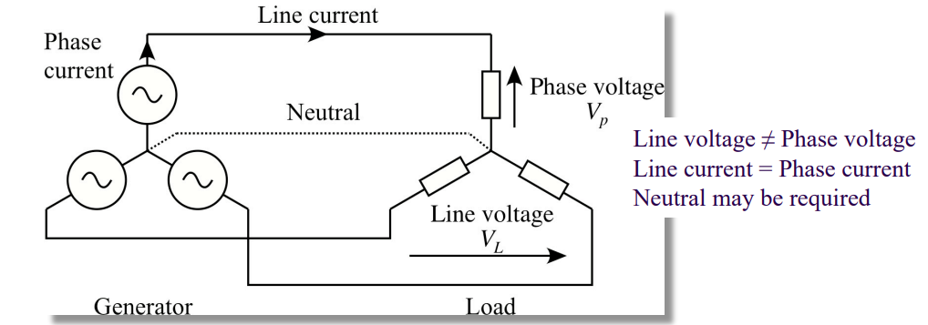
Three-phase system in a Star Config
Line Voltage (VL) ≠ Phase Voltage (VP)
Line current (IL) = Phase Current (IP)
Neutral may be required
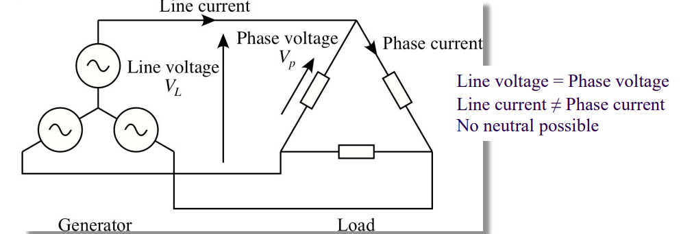
Three - Phase system in Delta config
Line Voltage (VL) = Phase Voltage (VP)
Line current (IL) ≠ Phase current (IP)
Neutral NOT possible
Synchronous machines
Rotor usually powered by a three-phase AC supply
Constant phase difference between Rotor magnet and Stator magnet
Run at a constant speed (revs / s)
Locked to a constant supply frequency

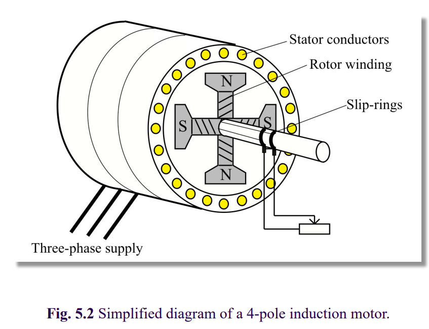
Induction machines
Rotor is a set of short circuited coils
Rotates at a higher frequency than that of the stator, and induces a current due to change in flux.
Running speed is less than synchronous speed (fractional slip)
Speed of rotation varies as load increases.
Synchronous motors
f = np
Supply frequency (f) ∝ revolution speed (n)
Supply frequency (f) ∝ number of poles on rotor (p)
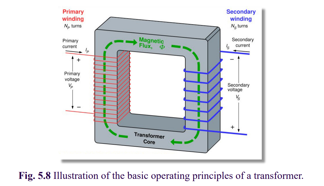
Properties of an Ideal Transformer
Zero winding impedance
Perfect soft-iron core
No fluyx leakage
No losses
Zero magnetising currents (No eddy currents)
transformer equivalent circut for a synchronous motor
The impedances highlighted in blue represent the internal impedances of the primary and secondary coils of the ideal transformer.
Re = core eddy current and hysterisis losses
jXN = magnetising flux

Losses in a Transformer
Iron loss
Losses due to Eddy current and hysterisis in the core.
Approximately constant with the load. {Re ∝ RL}
Copper loss
Due to I2R in the Transformer windings
Varies to the square of the load current.
Maximum efficiency of a transformer
copper Losses = Iron Losses