CSC258: Sequential Circuit Design
1/13
There's no tags or description
Looks like no tags are added yet.
Name | Mastery | Learn | Test | Matching | Spaced |
|---|
No study sessions yet.
14 Terms
Counters
store numbers and increment them, often implemented with a parallel load and clear inputs
ripple counter
example of an asynchronous circuit, timing isnt quite synchronized with the rising clock pulse, cheap to implement but unreliable for timing
how do you design these circuits?
sequential circuits are the basis for memory, instruction processing, and any other operation that requires the circuit to remember past data values
sequential circuits use combinational logic to determine what the next state of the system should be, based on the past state and the current input values
states of the circuit
past data values
state example: counters
with counters, each state is the current number that is stored in the counter
on each clock tick, the circuit transitions from one state to the next, based on the inputs
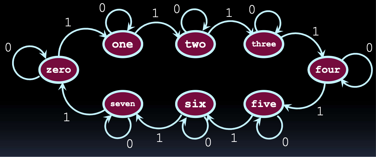
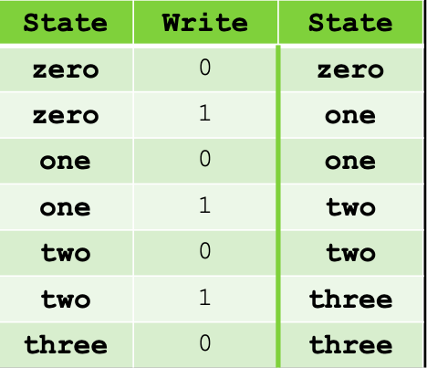
state tables
help to illustrate how the states of the circuit change with various input values f
finite state machines
is an abstract model that captures the operation of a sequential circuit
FSM definition
a finite set of states
a finite set of transitions between states, triggered by inputs to the state machine
output values that are associated with each state or each transition (depending on the machine)
start and end states for the state machine
design steps for FSM
draw state diagram
derive state table from state design
assign flip-flop configuration to each state
num of flip-flops needed is : ⌈log2(# of states)⌉
redraw state table w/ flip-flop values
derive combinational circuit for output and for each flip-flop input
moore machine
the output for the FSM depends solely on the current state (based on entry actions)
mealy machine
the output for the FSM depends on the state and the input (based on input actions)
being in state X can result in diff output, depending on the input that caused that state
timing and state diagrams
when assigning states, you need to consider the issue of timing witht he states
timing example
if recognizer circuit is in state 011 and gets a 0 as an input, it moves to state 110
the first and last digits change “at the same time”
if the first flip-flop changes first, the output would go high for an instant, which would cause unexpected behaviour
two solutions to race issue
whenever possible, make flip-flop assignments such that neighbouring states differ by at most one flip-flop value
intermediate states can be allowed if the output generated by those states is consistent with the output of the starting or destination states
if the intermediate states are unused in the state diagram, you can set the output for these states to provide the output that you need
might need to add more flip flops to create these states