HGE Formulas 01
1/73
Earn XP
Description and Tags
Hydraulics
Name | Mastery | Learn | Test | Matching | Spaced | Call with Kai |
|---|
No analytics yet
Send a link to your students to track their progress
74 Terms
Density
ρ = mass / volume
Density of Water
ρw = 1000 kg/m3 = 1.94 slugs/ft3
Specific Volume
ν = 1 / ρ = volume / mass
Weight
w = mg
Unit Weight
γ = w/v = mg / v
Unit Weight of Water and Air
γw = 9810 N/m3 = 62.4 lbs/ft3
γair = 12 N/m3
Specific Gravity
sg = γ / γw = ρ / ρw
Specific Gravity of Common Fluids
Freshwater: 1.00
Seawater: 1.03
Oil: 0.80
Mercury: 13.6
Glycerin: 1.25
Surface Tension: Pressure inside a Droplet
p = 4σ / d
p = gage pressure
σ = surface tension
d = diameter of droplet
Surface Tension: Capillary Rise
h = 4σ cosθ / γd
h = capillary rise or depression
θ = contact angle from vertical
d = diameter of tube
Viscosity
µ = τ / (dV / dy)
µ = viscosity
τ = shear stress
dV / dy = change in velocity wrt distance
Kinematic Viscosity
ν = µ / ρ
Compressibility
ß = (- dV / V) / dp = 1 / EB
dV / V = change in volume
dp = change in pressure
EB = bulk modulus of elasticity
Pressure
p = γh
pB = pA + γh
Pressure Head
h = p / γ
hB = sgA / sgB × hA
Absolute Pressure
pabs = patm + pgage
patm = 101.325 kPa = 1 atm = 760 mmHg = 760 torr = 14.7 psi
Gas Pressure (Absolute)
p = ρRT ; R = 287.4 Nm / kg K
p = γRT ; R = 29.3 m / K
T = Temperature in Kelvin (°C + 273 K)
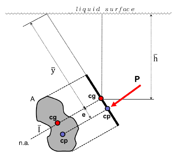
Hydrostatic Pressure: Plane Surface
P = γ × h-bar × A
e = I / Ay-bar
Location of Force: y-bar + e
h-bar = distance of the cg below the liquid surface “l.s.”, on the vertical
A = submerged area
e = distance of cp below the cg along the body
I = moment of inertia of A wrt centroidal axis
y-bar = distance of the cg below the liquid surface “l.s.”, on the vertical
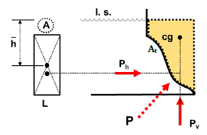
Hydrostatic Pressure: Curved Surface
Force = √(Ph2 + Pv2)
Ph = γ × h-bar × A → Location same as plane surface
Pv = γ × At × L = γ × Volume → Location at the c.g. of volume
Ph = Horizontal Component
Pv = Vertical Component
At = Area traced above the curved projection until the liquid surface
Archimedes’ Principle
BF = γf × Vd
BF = buoyant force
γf = unit weight of displaced fluid
Vd = volume of fluid displaced (body immersed)
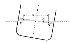
Distance of MBo
Rectangular Sections: MBo = B2 / 12D × [1 + 0.5 tan2 θ]
Other Sections (exact): MBo = v s / (V sinθ)
Approximate: MBo = I / V
θ = angle of tilting
v = volume of the wedge of immersion/emersion
s = horizontal distance between the centroids of v’s
I = moment of inertia of an area which is the top view of the body at the level of the liquid surface with respect to the axis of tilting
![<p>Rectangular Sections: MB<sub>o</sub> = B<sup>2</sup> / 12D × [1 + 0.5 tan<sup>2</sup> θ]</p><p>Other Sections (exact): MB<sub>o</sub> = v s / (V sinθ)</p><p>Approximate: MB<sub>o</sub> = I / V</p><p></p><p>θ = angle of tilting</p><p>v = volume of the wedge of immersion/emersion </p><p>s = horizontal distance between the centroids of v’s</p><p>I = moment of inertia of an area which is the top view of the body at the level of the liquid surface with respect to the axis of tilting</p>](https://knowt-user-attachments.s3.amazonaws.com/f668dd24-3bf0-41c7-8ef2-b78a4375f7b4.png)
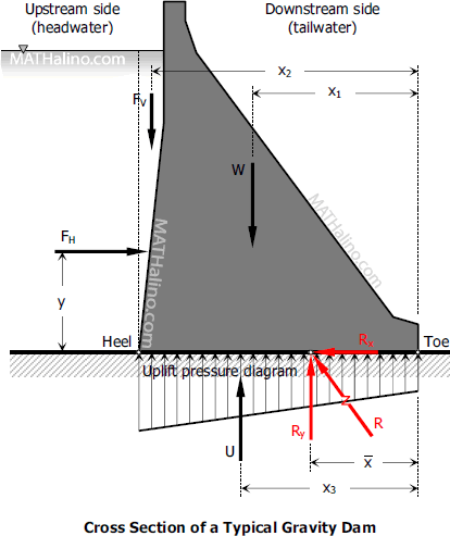
Dams: Factor of Safety against Overturning
FSO = RM / OM
RM = Righting Moment
OM = Overturning Moment
Note: Take moments at toe

Dams: Factor of Safety against Sliding
FSS = µRy / Rx

Dams: Location of Ry and e
x-bar = (RM - OM) / Ry
e = | B/2 - x-bar |
Dams: Foundation Pressure
If e ≤ B/6: q = Ry / B × (1 ± 6e / B)
If e > B/6: qmax = 2Ry / (3 × x-bar); qmin = 0
Hoop and Circumferential Stresses: Walls Carrying Stress in Pipes and Tanks
t = pD / 2St (eff)
t = thickness of the wall
D = inside diameter
p = unit pressure of fluid
St = actual or allowable tensile stress in the wall
eff = efficiency of the connections
Hoop and Circumferential Stresses: Hoops Carrying Stress in Pipes and Cylindrical Tanks
S = 2T / pD
S = center to center spacing of the hoops
T = tensile force in one hoop
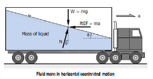
Moving Vessel: Horizontal Motion
tan𝜃 = a / g
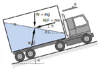
Moving Vessel: Inclined Motion
tan𝜃 = ah / (g ± av)
Note: (+) = upward motion, (-) = downward motion
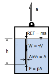
Moving Vessel: Vertical Motion
p = γh (1 ± a / g)
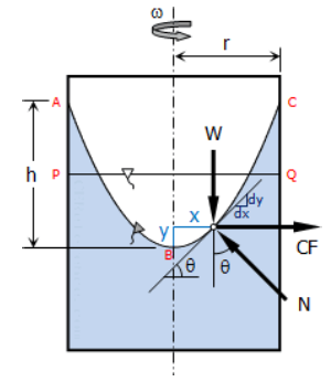
Rotating Vessel
tan𝜃 = ω2 x / g
y = ω2 x2 / 2g
r2 / h = x2 / y
Note: 1 rpm = π/30 rad/sec
Fluid Flow: Discharge
Q = AV
A = cross-sectional area of flow
V = velocity of flow
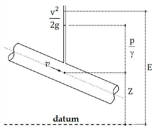
Total Head/Energy
E = v2 / 2g + p / 𝛾 + z
Velocity Head: v2 / 2g
Pressure Head: P / 𝛾
Elevation Head: z
Bernoulli’s Principle of Fluid Flow
Theoretical: v12 / 2g + p1 / 𝛾 + z1 = v22 / 2g + p2 / 𝛾 + z2
Actual: v12 / 2g + p1 / 𝛾 + z1 = v22 / 2g + p2 / 𝛾 + z2 + HL
w/ Pump or Turbine: v12 / 2g + p1 / 𝛾 + z1 + HA = v22 / 2g + p2 / 𝛾 + z2 + HL + HE
HL = head loss
HA = head added by pump
HE = head extracted by turbine
Slope of EGL
S = HL / L
Power of Pump or Turbine
P = Q 𝛾 E
E = HA (pumps) or HE (turbines)
Efficiency of Pump/Turbine
Eff = Output / Input
HA - Output
HE - Input
Head Loss: Darcy-Weisbach
General Formula: hf = fL / D × v2 / 2g
Circular Pipes: hf = 0.0826fL Q2 / D5
Head Loss: Manning Formula
General Formula: hf = 6.35 n2L v2 / D4/3
Circular Pipes: hf = 10.29 n2L Q2 / D16/3
Head Loss: Hazen-Williams Formula
General Formula: v = 0.8492 C R0.63 S0.54
Circular Pipes: hf = 10.67LQ1.85 / (C1.85D4.87)
Hydraulic Radius for non-circular pipe
R = A / P
D = 4R
Note: P = wetted perimeter
Minor Head Loss
hm = km v2 / 2g
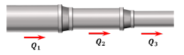
Pipes in Series
Q1 = Q2 = Q3
HL = hf1 + hf2 + hf3
hf = Δp / γ
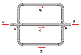
Pipes in Parallel
Q = Q1 + Q2 + Q3
hf1 = hf2 = hf3
Celerity for rigid pipes
c = √(EB / ρ)
Celerity for Non-Rigid Pipes
c = √(EC / ρ)
1/EC = 1/EB + d/Et
d = internal diameter of pipe
E = modulus of elasticity of pipe material
t = pipe thickness
Water Hammer: Time required for the pressure wave to travel from the
valve to the reservoir and back to the valve is:
T = 2L / c
Water Hammer Pressure
Rapid Closure (tc < 2L/c): Ph = ρcv
Slow Closure (tc > 2L/c): Ph’ = 2Lρv/tc
Reynold’s Number
NR = VD / ν
V = velocity of flow
D = diameter of pipe
ν = kinematic viscosity
Friction Factor given Reynold’s Number
NR < 2000: f = 64 / NR
NR > 2000: 1 / √f = -2log(ε / 3.7D + 2.51 / NR√f)
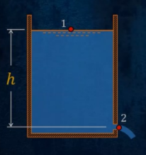
Torricelli’s Formula for Orifice
Theoretical: v2 = √2gh
Actual: v = Cv√2gh
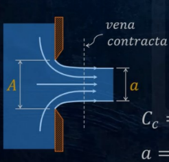
Orifice: Vena Contracta
Cc = a/A
C = Cc Cv
Q = av = CcCvA√2gh = CA√2gh
HL = v2 / 2g × (1 / Cv2 - 1)
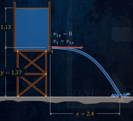
Projectile of Orifice
x = v1x t
y = v1y t - ½ gt2
v2y2 = v1y2 - 2gy
y = xtanθ - gx2 / (2v12 cos2θ)
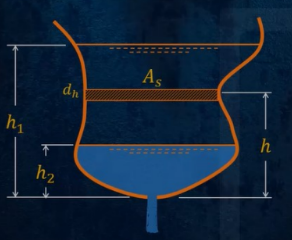
Falling Head: Orifice
General Formula: t = ∫ Asdh / CA√(2gh) from h2 to h1
Constant As: t = 2As / (CA√2g) × (√h1 - √h2)
Open Channel: Discharge and Velocity
Q = Av
v = C√RS (Chezy Formula)
Chezy Coefficient
Theoretical: C = √(8g / f)
Manning: C = 1/n × R1/6
Bazin: C = 87 / (1 + m/√R)
Note: m and n are roughness coefficients
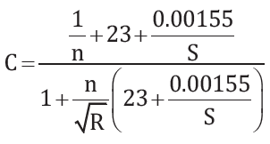
Kutter’s Formula
Chezy-Manning Formula
v = 1/n × R2/3 × S1/2
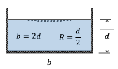
Open Channel: Most Efficient Rectangular Section
b = 2d
R = d/2
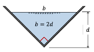
Open Channel: Most Efficient Triangular Section
b = 2d
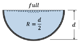
Open Channel: Most Efficient Semicircular Section
channel is full; R = d/2
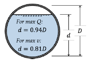
Open Channel: Most Efficient Circular Section
Max Q: d = 0.94D
Max v: d = 0.81D
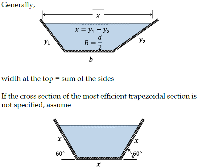
Open Channel: Most Efficient Trapezoidal Section
For given cross-section: x = y1 + y2 and R = d/2
For cross-section not specified: x = y1 = y2 (half regular hexagon)
Froude Number
NF = v / √gdm
dm = average depth = A/B
B = width of liquid surface
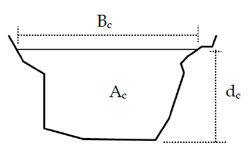
Critical Depth
Q2 / g = Ac3 / Bc ; q = discharge per meter width
Rectangular Sections:
dc = 3√q2 / g
dc = 2/3 × Ec; Ec = vc2 / 2g + dc
Critical vs. Subcritical vs. Supercritical Flow
Critical: NF = 1
Subcritical: NF < 1
Supercritical: NF > 1
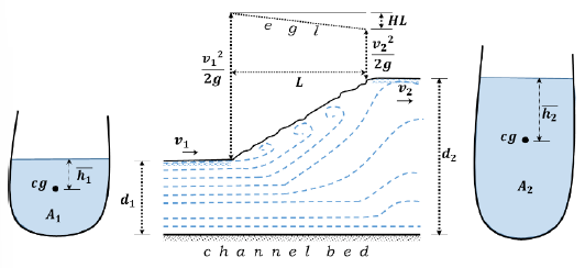
Hydraulic Jump
Power lost = Qγ(HL)
P2 - P1 = Qγ/g (v1 - v2)
Rectangular Section: q2 / g = d1 d2 (d1 + d2) / 2
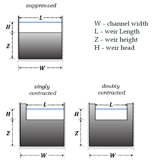
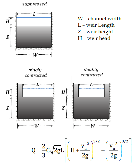
Rectangular Weir
Q = mLH3/2 or Q = 1.84LH3/2 (Francis formula)
For contracted sections:
L’ = L - 0.1H (singly contracted)
L’ = L - 0.2H (doubly contracted)
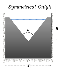
Triangular Weir
Q = 8/15 × C√2g × tan(θ/2) × H5/2
Q = 1.4H5/2 for θ = 90°
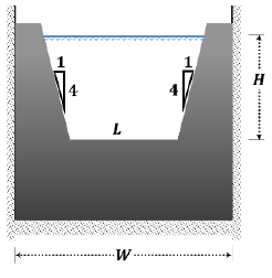
Cipolletti Weir
Q = 1.86LH3/2
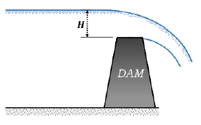
Broad-Crested Weirs (Dams)
Q = 1.71LH3/2
L = length of dam
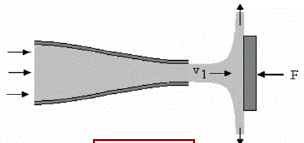
Impact of a Jet on a Plane/ Force on the Jet
F = ρQv
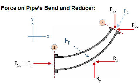
Force on Pipe’s Bend and Reducer
ΣFx = ρQ (v2x - v1x)
ΣFy = ρQ (v2y - v1y)
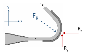
Force on a Curved Vane/Blade
ΣFx = ρQ (v2x - v1x)
ΣFy = ρQ (v2y - v1y)