Arduino
1/62
Earn XP
Name | Mastery | Learn | Test | Matching | Spaced | Call with Kai | Chat |
|---|
No analytics yet
Send a link to your students to track their progress
63 Terms
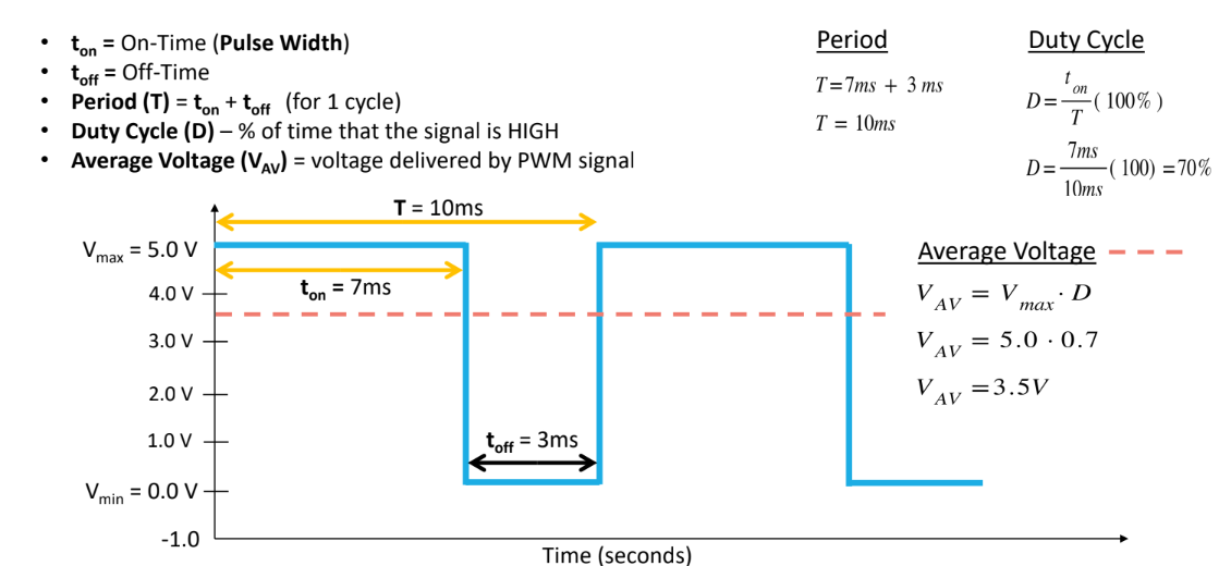
PWM
A technique that allows you to simulate an analog signal using digital means
PWM values range
[0, 255]
potentiometer values range
[0, 1023]
Wire color conventions
Black: ground
Red: 5V
Orange: 3.3V
Other colors for signal wires
digital pins
allows you to connect digital sensors and other integrated circuits
allow you to read digital inputs and control outputs
digital signals are either HIGH (1) or LOW (0)
pins 0-13 for GPIO
digital pins 3, 5, 6, 9, 10, 11 have a ~
allows you to perform PWM
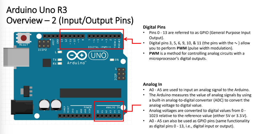
Analog In
used to read analog inputs
analog signals can take an infinite number of values within a range of values
A0 - A5 used to input analog signal from Arduino
Arduino measures the value of analog signals by using ___, which converts ___ to ___
analog-to-digital converter (ADC); analog voltage; digital value
Analog voltages are converted to digital values from the range __
[0, 1023]
pushbuttons (momentary switch)
Push button → make connection → current flows from one of the side of the switch to the other side of the switch
Metal bar connects pins A and B
Metal bar connects pins C and D
Closing switch → connection pints A & B with pins C & D → allows current to pass through switch
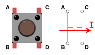
use ___ to read button state
digitalRead(btnPin)
To send PWM value from Arduino to RGB LED, use ___
analogWrite(pin, value)
Examples:
analogWrite(redPin, 255) – red on at 100% intensity
analogWrite(redPin, 0) – red off (on at 0% intensity)
analogWrite(redPin, 127) – red on at 50% intensity
The longest pin of an RGB LED is the _____
common cathode
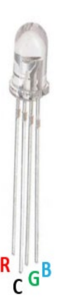
The common cathode of an LED is connected to (5V/Ground)
ground
purpose of delayMicroseconds()
delay the operation for specified microseconds
When writing code for a range finder, use ___ to set the trigPin to HIGH or LOW
digitalWrite(trigPin, HIGH)
digitalWrite(trigPin, LOW)
what does pulseIn(echoPin, HIGH) do?
receive the echo signal and returns soundwave travel time in microseconds.
analogWrite()
used to send a PWM value from the Arduino to the LED’
analogWrite(pin, value)
Pin - arduino PWM pin
Value - integers in range [0, 255]
![<p>used to send a PWM value from the Arduino to the LED’</p><ul><li><p><strong><span>analogWrite(pin, value)</span></strong></p><ul><li><p><span>Pin - arduino PWM pin </span></p></li><li><p><span>Value - integers in range [0, 255]</span></p></li></ul></li></ul>](https://knowt-user-attachments.s3.amazonaws.com/95440747-79a7-4680-8133-627fa2d8c168.png)
How to avoid floating pin
Connect the switch to ground using a very large resistor (10 kΩ). If any signals are detected while the button is not pressed, the large resistance will reduce the signal level to almost zero keeping the state LOW.
Debouncing
Add a timing delay of 10ms to wait out the contact bounce period
How does a rangefinder work?
Transmitter (trig pin) sends a sonic burst that travels at the speed of sound.
The sound wave will reflect off the object creating an echo wave.
The echo wave is received by the receiver (echo pin).
Echo pin outputs the time in microseconds that the sound wave traveled.
Formula to calculate object distance based on time echo pin outputs
d = 0.034(t/2)
Object Distance (cm) = speed of sound (cm/μs) * time (μs) /2
when using a range finder, connection Vcc and GND to the wrong places results in a ___
short circuit
the trig pin and echo pin of a range finder can be connected to any ___
digital pin
Temperature sensor is an ___ input
analog
Formulas for temperature sensor
VOUT = reading from ADC • (5000/1024)
Temperature (°C) = (VOUT - 500)/10
Orientation of temperature sensor
flat face should face you
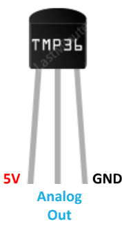
use ___ to read input from temperature sensor
analogRead(tempPin)
Unpolarized light
light that vibrates in multiple directions
Polarized light
light that vibrates in one direction
Polaroid Filter
blocks one of the two planes of vibration of an electromagnetic wave, polarizing it.
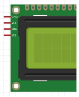
LCD
Liquid Crystal Display
Reflective LCD
uses a mirror to reflect environmental light
Backlit LCD
LEDs are used to provide the light source
Purpose of I2C
reduces the number of data pins from 6 to 2 by using the SDA (Signal Data) and SCL (Signal Clock) pins on the Uno instead of digital I/O pins.
A potentiometer is an ____
Analog Sensor
linear interpolation setup
map(value, 0, 1023, 0, 255)
map(value, fromMin, fromMax, toMin, toMax)
Use linear interpolation to map given value in [fromMin, fromMax] to corresponding value in [toMin, toMax]
Arduino simulates analog signals using PWM. Instead of varying supply voltage and rapidly switching between HIGH and LOW, it uses the ___ voltage provided
average
read potentiometer value using ___
analogRead(potentiometer)
When using a potentiometer, if you connect 5V to terminal 2, which way would you turn the potentiometer to increase the values?
clockwise (this orientation is used most often)
When light exposure is light, photoresistors have __ resistance
low (∼1 kΩ)
When light exposure is dark, photoresistors have __ resistance
high (∼ 10 kΩ)
How do arduino analog pins measure a photoresistor’s change in voltage?
Since arduino analog pins measure change in voltage, to measure photoresistor’s resistance, a 10 kΩ resistor is used to create small current. This allows arduino to measure voltage across photoresistor
when using a photoresistor, voltage at pin is measured using ___ function
analogRed(photoResistor)
As the amount of light detected increases, the value returned will increase.
electric motors convert _ energy to mechanical energy
electrical
How are DC motors able to turn?
In a DC motor, a wire with current running through it is passed through a magnetic field → magnetic force produces torque → turns motor. Commutator reverses current each half turn to keep torque turning motor in same direction.
Motors act as __
inductors
Stores energy in magnetic filed
Opposes sudden changes in current
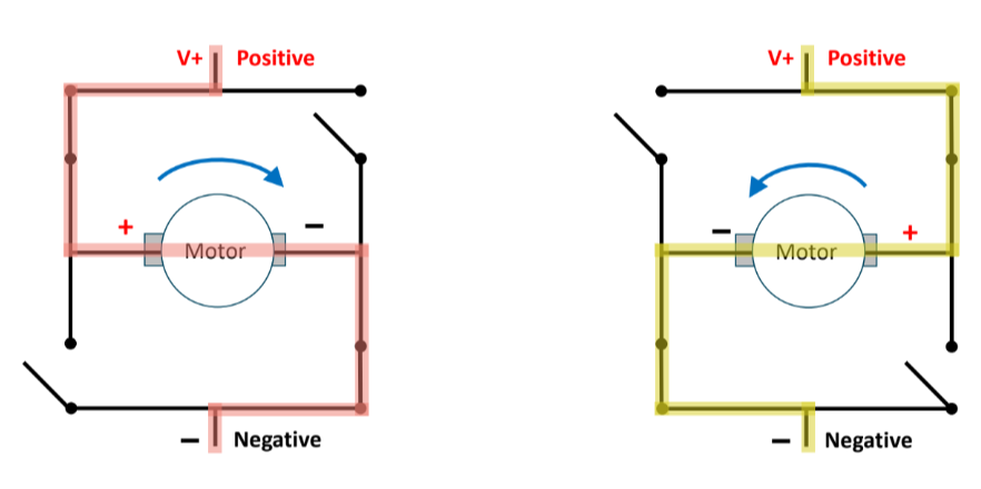
an __ controls motor direction
H-bridge
To control rotation direction, reverse direction of current flow into motor
Speed of motor controlled by PWM
H-bridge, a circuit, reverses direction of current flow
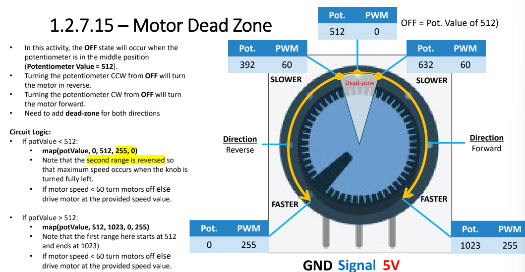
Why do motor dead zones exist?
Sufficient voltage needs to be supplied to overcome friction in motor for shaft to turn
If voltage is insufficient, buzzing sound will occur
To prevent buzzing, PWM value of minimum speed is required to get the motor to turn
Use this threshold value as the dead-zone
Any motor speed value below threshold results in motor remaining OFF
If motor is not carrying load, don’t….
run motor at max. speed. keep PWM value below 150
which coding function is used to control motor direction
digitalWrite()
digitalWrite(in1, HIGH) - turn motor in forward direction
digitalWrite(in1, LOW) - turn motor off
To reverse motor, how would you modify the linear interpolation setup?
map(potValue, 0, 512, 0, 255) → map(potValue, 0, 512, 255, 0)
second range is reverse so max. speed occurs when knob is turned fully left
Coding conventions
Import necessary libraries
Include a program header that includes your name, section, assignment/program function
Define constants and variables
Be consistent
Do not mix and match camCase or under_scores
Use descriptive names
Define void setup()
Initialize pin modes, libraries, etc
pinMode(), Serial.begin(9600),
Define void loop()
Always keep code in the void loop
This is the “main” program
Use helper functions
Define helper functions
Don’t Repeat Yourself - DRY
Create reusable, modular code
Comment your code
Avoid obvious comments
Comments should help non-coder follow the program’s logic
fill in the blank: pinMode(trigPin, ____)
OUTPUT
fill in the blank: pinMode(echoPin, ____)
INPUT
fill in the blank: pinMode(photoResistor, ____)
INPUT
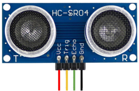
anatomy of Ultrasonic sensor/range finder
Vcc - connected to 5V
Gnd - Ground
Trig - trigger (transmits sonic pulse)
Echo - receives the echo pulse
Analog signal
smooth, continuous curve
Range: real numbers
Used for temperature, sound intensity, light intensity
Used for resistors, capacitors, inductors, diodes, transistors, and operational amplifiers
Circuits with these components are analog
Can be more difficult to design
Susceptible to noise
Small voltage variations - can result in processing errors
Digital Signal
series of discontinuous levels (step function)
Range: real numbers
Width of the step is determined by sampling rate
Faster sampling rate = reduced step width and increased signal accuracy
Music sampling range is from 8 kHz to 22.6 MHz
Used for signals for microcontrollers
Signals have different logic levels
High: 5V, 3.3V, 1,8V
Low: 0V
Easier to design than analog circuit but more expensive
Faster sampling rates __ width of step, which increases the accuracy of the analog to digital conversion
reduce
How to import library
Tool → Manage Libraries → search for the thing → download thing
What does a capacitor do?
it reduces noise
noise is small, undesired voltage variations
What is contact bounce?
metal contacts come together and bounce because of spring-like properties
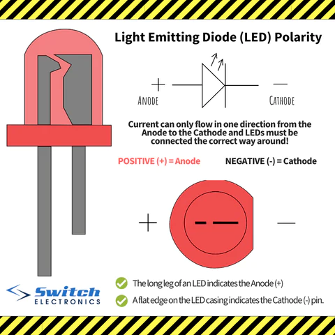
LED anatomy
longer leg: anode (+)
shorter leg: cathode (-)
current flow from anode → cathode