Arduino
Introduction to Arduino
Arduino is an open-source prototyping platform used for building electronic projects by processing electrical signals (analog or digital)
Analog Signals: smooth, continuous curve
Range: real numbers
Used for temperature, sound intensity, light intensity
Used for resistors, capacitors, inductors, diodes, transistors, and operational amplifiers
Circuits with these components are analog
Can be more difficult to design
Susceptible to noise
Small voltage variations - can result in processing errors
Advantages | Disadvantages |
|---|---|
|
|
Digital Signals: series of discontinuous levels (step function)
Range: real numbers
Width of the step is determined by sampling rate
Faster sampling rate = reduced step width and increased signal accuracy
Music sampling range is from 8 kHz to 22.6 MHz
Used for signals for microcontrollers
Signals have different logic levels
High: 5V, 3.3V, 1,8V
Low: 0V
Easier to design than analog circuit but more expensive
Advantages | Disadvantages |
|---|---|
|
|
Analog and Digital Conversion
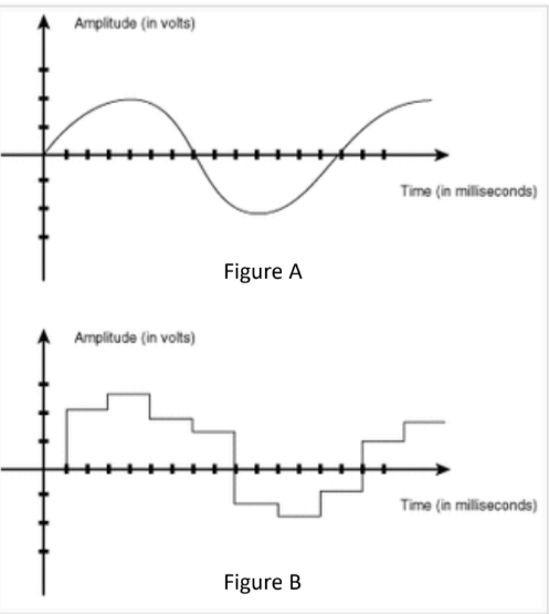
Signal quality is lost during conversion
Analog to digital conversion is done by measuring voltage at equally spaced points in time (sampling rate)
Faster sampling rates reduce width of step, which increases accuracy of conversion
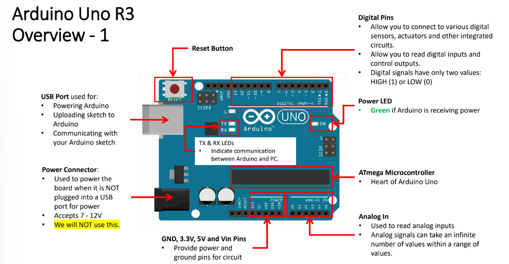
Arduino Uno
Wire Color Conventions
Black: ground
Red: 5V
Orange: 3.3V
Other colors for signal wires
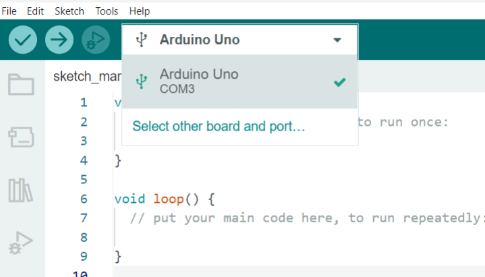
Code Setup
Import necessary libraries
Include a program header that includes your name, section, assignment/program function
Define constants and variables
Be consistent
Do not mix and match camCase or under_scores
Use descriptive names
Define void setup()
Initialize pin modes, libraries, etc
Define void loop()
Always keep code in the void loop
This is the “main” program
Use helper functions
Define helper functions
Don’t Repeat Yourself - DRY
Create reusable, modular code
Comment your code
Avoid obvious comments
Comments should help non-coder follow the program’s logic
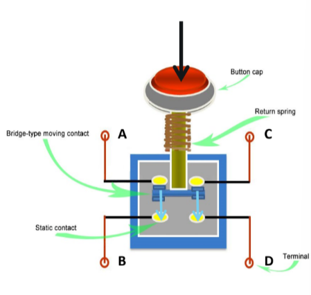
Working with Pushbuttons
Pushbutton = momentary switch
Push button → make connection → current flows from one of the side of the switch to the other side of the switch
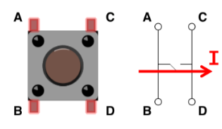
Metal bar connects pins A and B
Metal bar connects pins C and D
Closing switch → connection pints A & B with pins C & D → allows current to pass through switch
Floating pins
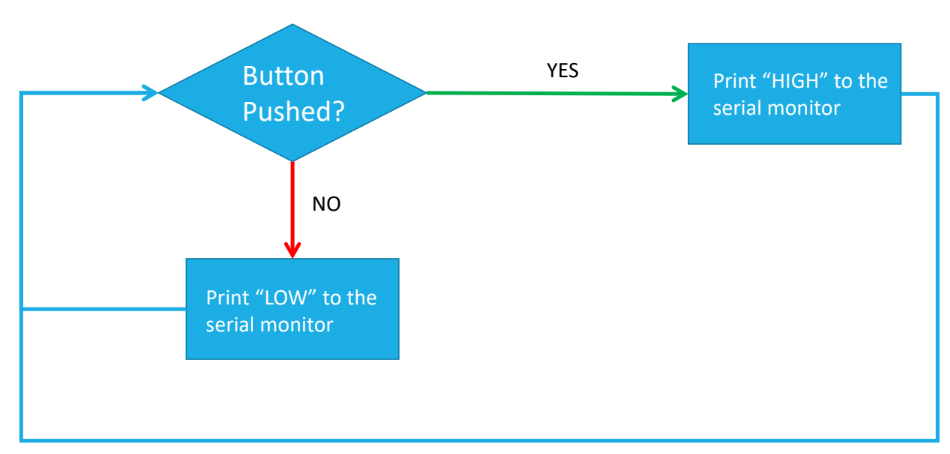
The button state (HIGH or LOW) should only change when you want it to
Input pins are sensitive when it comes to detecting signals
Floating: without correction state, pin state floats on water, bobbing up and down
Bobs between different signal levels
Causes unpredictable behavior
Example: digital input pin meant to read the state of a button may detect a wireless signal from the environment and incorrectly return a button state of High (1) instead of Low (0)
Fix floating pins
Connect the switch to ground using a very large resistor (10 kΩ). If any signals are detected while the button is not pressed, the large resistance will reduce the signal level to almost zero keeping the state LOW.
Contact Bounce
Normally open contacts - N.O.
When they close or open, the thin mental contacts come together and bounce off each other like a spring
This happens during the first milliseconds before making a solid connection
Occurs because contacts are make from spring-like metals
Contacts are designed to open and close quickly
Little resistance to movement
Arduino has response time of microseconds - will be able to detect and respond to bouncing
Debouncing: Add a timing delay of 10ms to wait out the contact bounce period
Hardware debouncing: reduce KE using buffer springs and shock absorbers
Software debouncing: add time delay or use function to resolve bounce

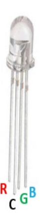
Using the RGB LED
Contains 2 individual LEDs with a common cathode, the longest pin that gets connected to ground
R - red
G - green
B - blue
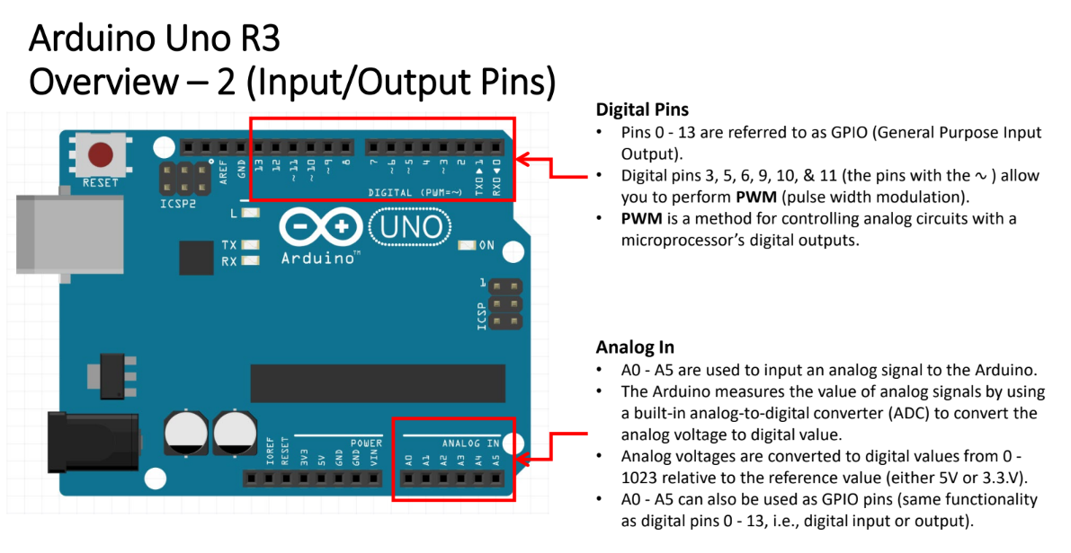
Use Arduino’s digital I/O pints with PWM (marked with ~) to specify RGB colors
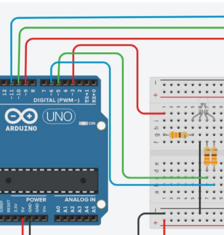
To send PWM value from Arduino to LED, use analogWrite function
analogWrite(pin, value)
analogWrite(redPin, 255) – red on at 100% intensity
analogWrite(redPin, 0) – red off (on at 0% intensity)
analogWrite(redPin, 127) – red on at 50% intensity
Ultrasonic Sensor (Range Finder)
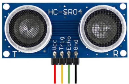
Vcc - connected to 5V
Gnd - Ground
Trig - trigger (transmits sonic pulse)
Echo - receives the echo pulse
Trig pin sends a sonic burst → sound wave will reflect off object → create echo wave → echo wave received by echo pin, the receiver → echo pin outputs time (in microseconds) that the sound wave traveled
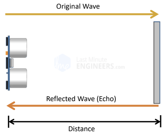
Object Distance (cm) = speed of sound (cm/μs) * time (μs) /2
Speed of Sound (@ 20°C/68 °F) = 343 m/s or 0.034 cm/μs
Time = distance / speed (this is the time that it takes the signal to travel from the transmitter to the object and back to the receiver)
Use long datatype for the duration, an int datatype for the distance, and float datatype for the speed of sound.
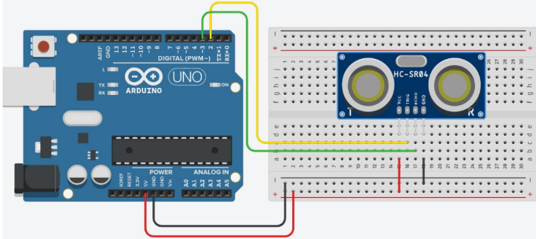
Make sure to connect Vcc to 5V and GND to GND
Connecting backwards = short circuit
Trig and echo can be connected to any digital pin
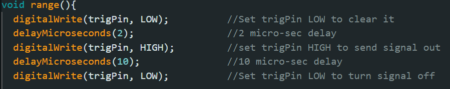
delayMicroseconds(); – delay the operation for specified microseconds
digitalWrite(); – used to set the trigPin HIGH or LOW
pulseIn(echoPin, HIGH); – receive the echo signal and returns soundwave travel time in microseconds.
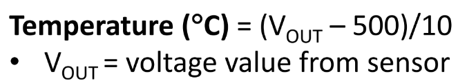
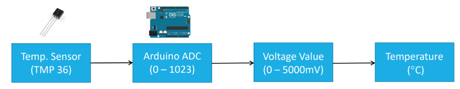
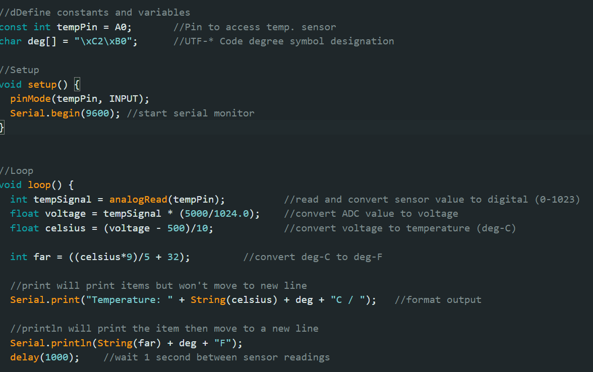
Temperature Sensor
analog input
Connects to analog input pins (A0 - A5)
analogRead(tempPin) is used to read input from temperature sensor
Build int analog to digital converter (ADC) converts analog signal from sensor to digital one
Values returned by ADC range is from 0-1023
ADC value is converted to voltage value (in mV), which is then converted to temperature value
Arduino Uno pins operate on 5V, which results in a resolution of 5000mV/1024 units or 4.9V per unit


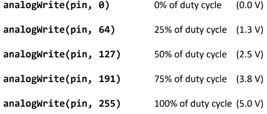
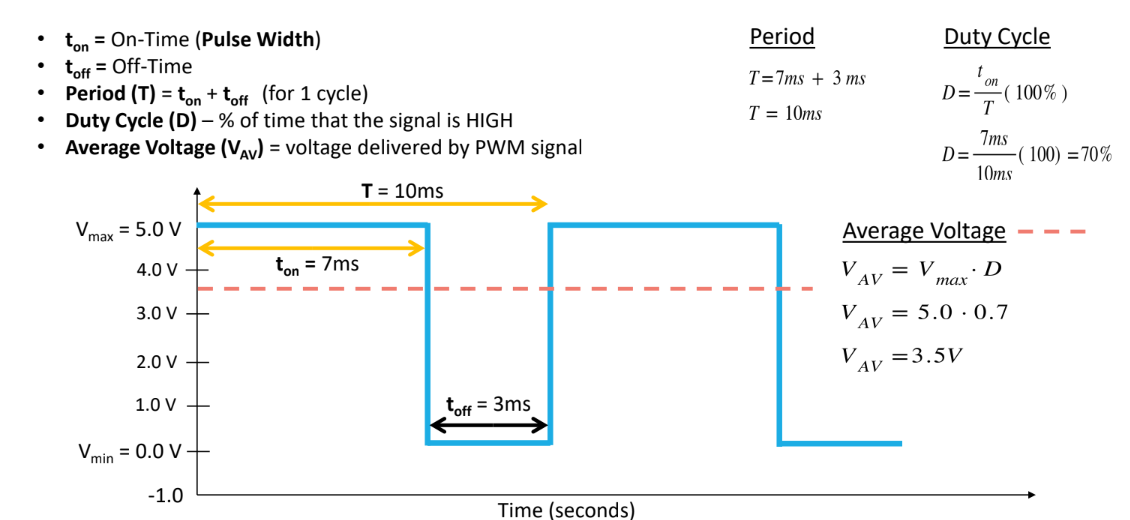
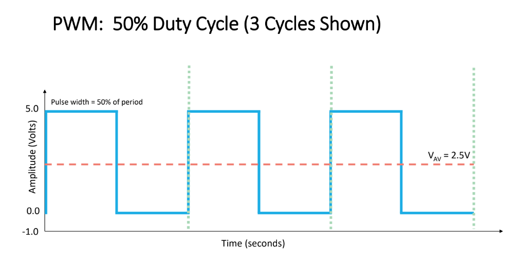
Pulse Width Modulation (PWM)
PWM: A technique that allows you to simulate an analog signal using digital means

analogWrite(): used to send a PWM value from the Arduino to the LED
analogWrite(pin, value)
Pin - arduino PWm pin
Value - integers in range [0, 255]
2 possible supply voltage values: 5V (HIGH) and 0V (LOW)
Analog signals have an infinite number of values within range
Arduino simulates analog signals using PWM
Instead of varying supply voltage between 0V and 5V (rapidly switching between HIGH and LOW), it uses the average voltage provided by signal
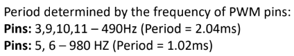
If PWM signal generated at pins 3, 9, 10, 11, there would be 490 cycles per second
Duty Cycles
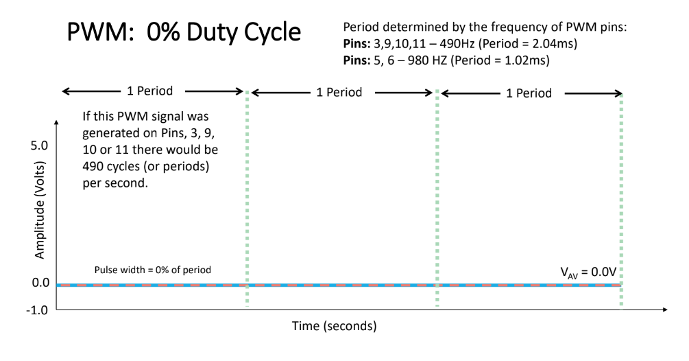
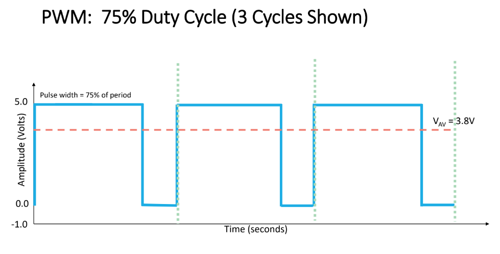
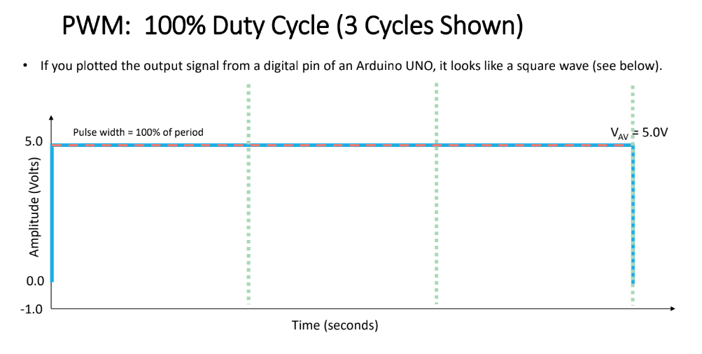
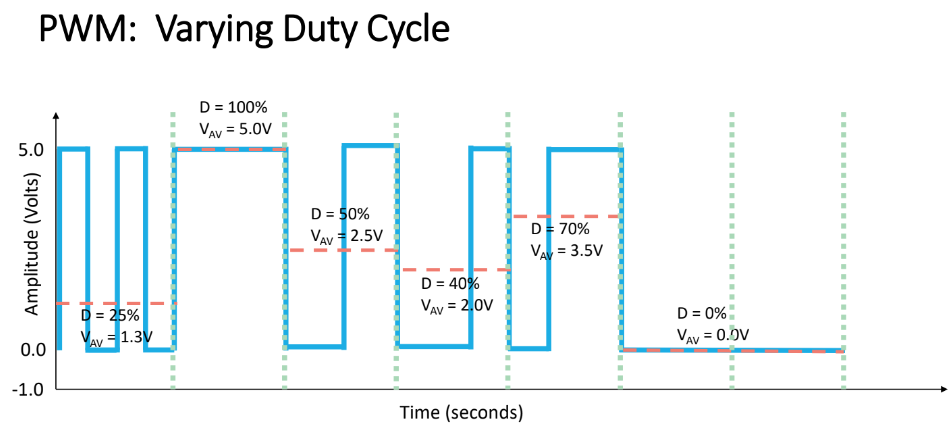
LED brightness with duty cycles of 4%, 20%, 50%, 100%

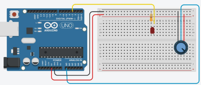
Potentiometer
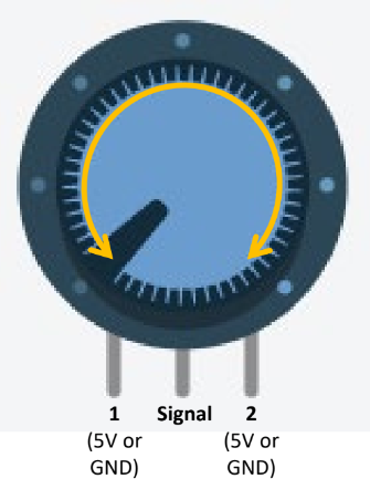
Allows you to change resistance by turning know
Signal pin connection to analog ports (A0 - A5)
Returns value [0, 1023], corresponding to amount of electricity the analog pin receiver
analogRead() reads potentiometer value
Connect 5V to terminal 2: turn clockwise to increase (used most often)
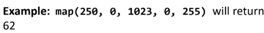
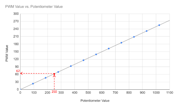
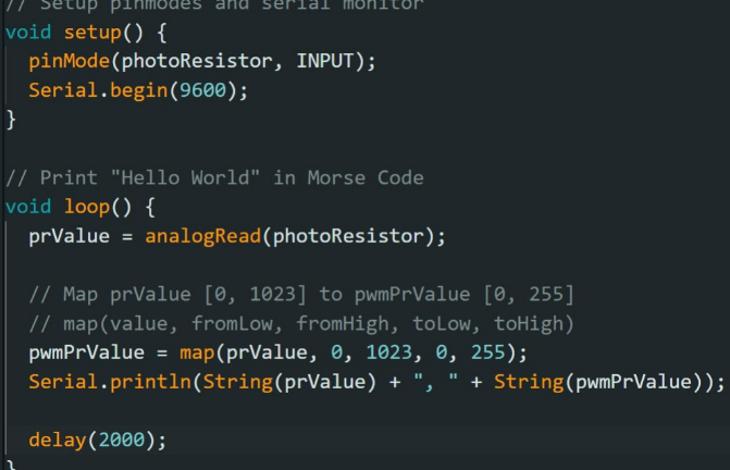
Converting potentiometer values to PWM values
Potentiometer: 0-1023
PWM: 0-255
Linear mapping used
map(value, fromMin, fromMax, toMin, toMax)
Use linear interpolation to map given value in [fromMin, fromMax] to corresponding value in [toMin, toMax]
Must use integer math
Fractional components are truncated
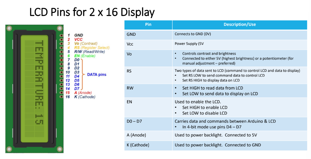
Liquid Crystal Display (LCD)
Unpolarized light: light that vibrates in multiple directions
Polarized light: light that vibrates in one direction
Polaroid filter: blocks one of the two planes of vibration of an electromagnetic wave, polarizing it.
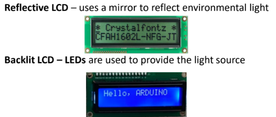
Used to display text
When an electric charge is applied to liquid crystal molecules, they untwist, changing their alignment
This change in alignment affects if it blocks polarized light or not
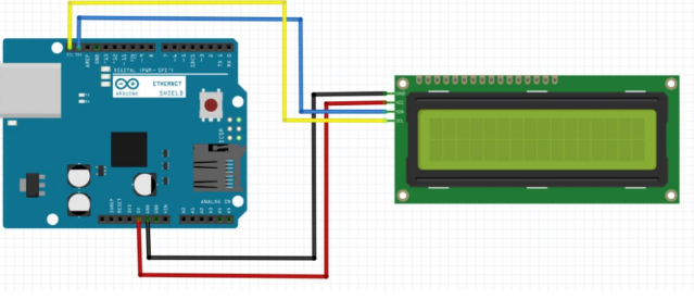
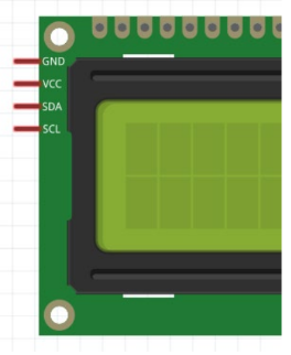
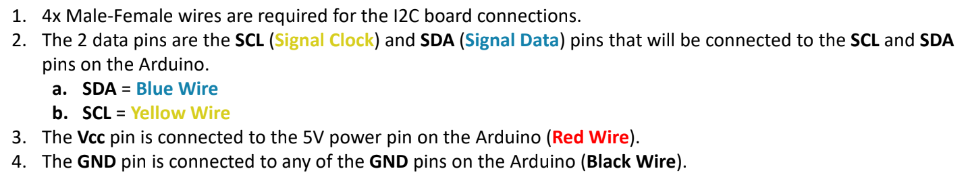
I2C (Inter-Integrated Circuit)
Better method for connecting LCD to arduino
LCDs normally require 6 data pins and 2 power pins, which could potentially cause shortage of pins for larger projects
LCDs with a board on back with 4 pins have an I2C expansion board
I2C expansion board reduced number of data pins from 6 to 2 using SDA and SCL pins
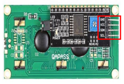
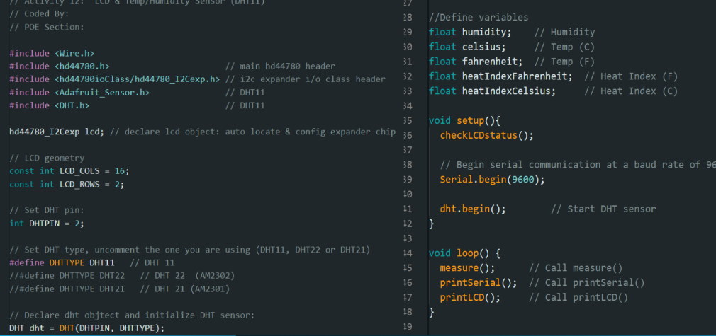
Use hd44780 library
Temp/Humidity Sensor with LCD
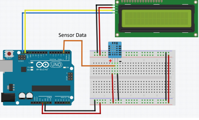
DHT11 Temperature and Humidity sensor
Connects to digital pin 2
Use DNT sensor library
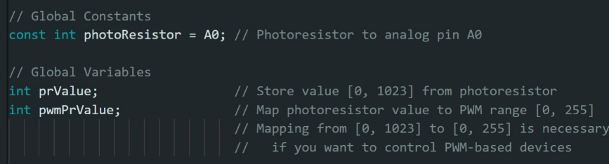
Photoresistor
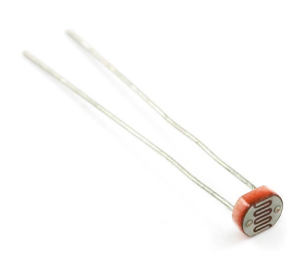
Photodetector, light detector, CdS, photoconductive cell, LIGHT SENSOR
Changes resistance depending on light exposure intensity
Light -> low resistance: ∼1 kΩ
Dark -> high resistance: ∼ 10 kΩ
Since arduino analog pins measure change in voltage, to measure photoresistor’s resistance, a 10 kΩ resistor is used to create small current
This allows arduino to measure voltage across photoresistor

analogRead() used to measure voltage
ADC converter will convert voltage to a value in [0, 1023]
As amount of light detected increase, value returned increases
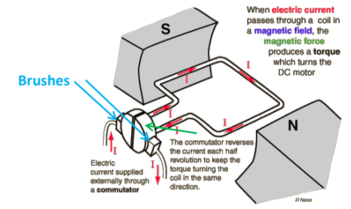
Motor Control
Electric motors convert electrical energy to mechanical energy
In a DC motor, a wire with current running through it is passed through a magnetic field → magnetic force produces torque → turns motor
Commutator reverses current each hald turn to keep torque turning motor in same direction
Motor acts as inductor
Stores energy in magnetic filed
Opposes sudden changes in current
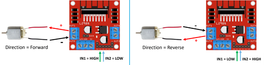
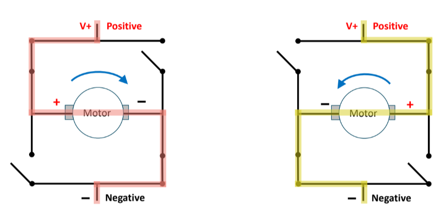
H-Bridge
Controls motor direction
To control rotation direction, reverse direction of current flow into motor
Speed of motor controlled by PWM
H-bridge, a circuit, reverses direction of current flow
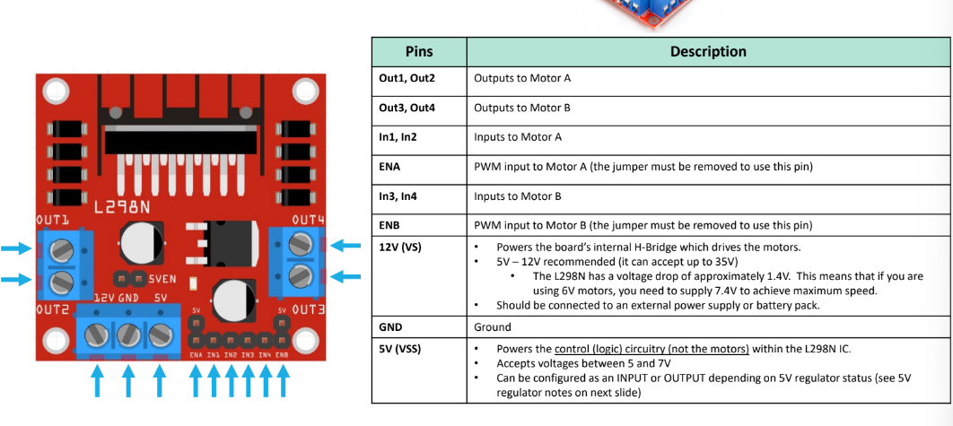
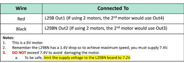
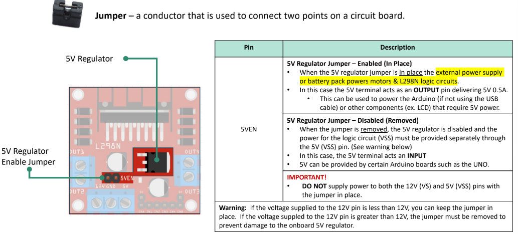
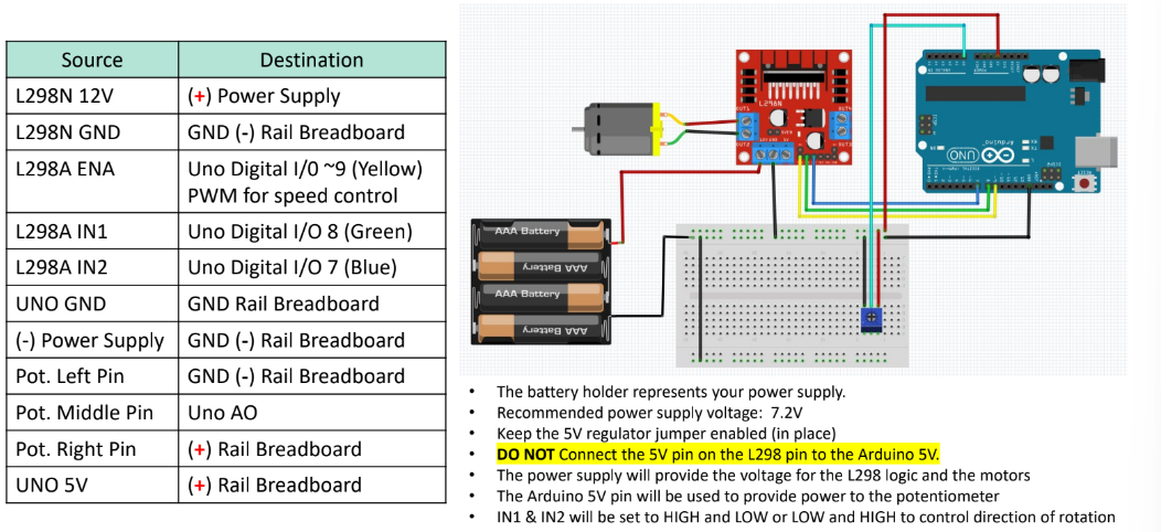
L298N Motor Driver
Motor Dead Zone (Activity 1.2.7.14)
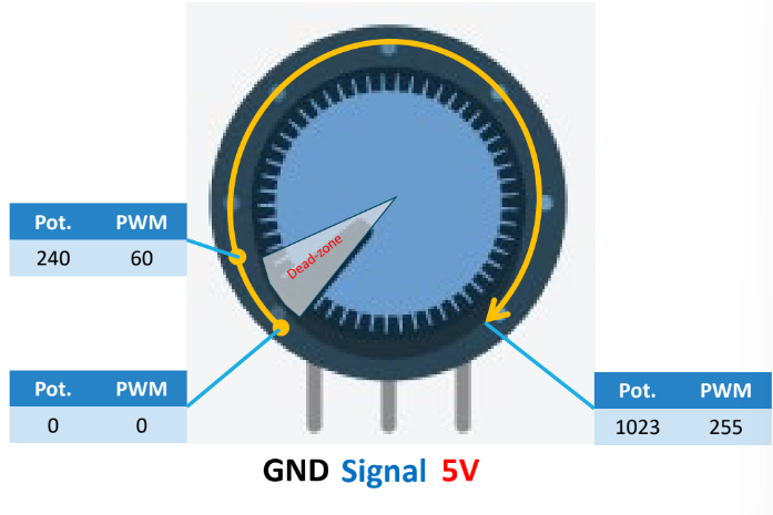
Turn know CW → motor speed increases in forward direction
Dead-zone
Sufficient voltage needs to be supplied to overcome friction in motor for shaft to turn
If voltage is insufficient, buzzing sound will occur
To prevent buzzing, PWM value of minimum speed is required to get the motor to turn
Use this threshold value as the dead-zone
Any motor speed value below threshold results in motor remaining OFF
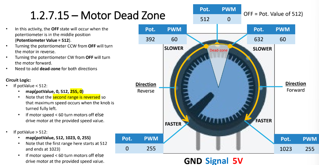
Motor Dead Zone (Activity 1.2.7.15)
Code
If motor has no load, don’t run motor at max speed
Keep PWM value below 150
Use digitalWrite() to control motor direction
digitalWrite(in1, HIGH) - turn motor in forward direction
digitalWrite(in1, LOW) - turn motor off
Set motor control pins to OUTPUT
pinMode(in1, OUTPUT)
Set potentiometer to INPUT