Resistors (W4.1/4.2 - Chap 2.4 - 2.8)
1/38
There's no tags or description
Looks like no tags are added yet.
Name | Mastery | Learn | Test | Matching | Spaced | Call with Kai |
|---|
No study sessions yet.
39 Terms
resistivity, p (not the letter p, but the Greek lowercase letter rho)
intrinsic ability of material to RESIST the flow of charge
depends on ONLY the material, not size or length
units: Ohm-meter (Ω·m)
built-in characteristic of a material
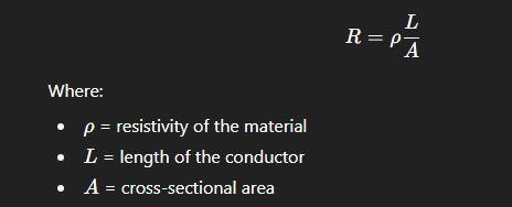
resistance, R
the opposition to the flow of current in an elem
depends on resistivity, length, cross sectional area // thickness (see notes for diagram)
units: Ohms (Ω)
formula for R using p (rho), L, and A
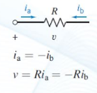
resistance (R) in relation to Ohm’s Law
Ohm’s Law: v = R*i
therefore, R = v/i where 1Ω = 1V/1A
(rmbr: elem must be LINEAR for this to apply, you can assume a resistor is linear unless stated otherwise)
conductance, G
physical property reciprocal to the resistance, describes an elem’s ability to encourage the flow of current.
G = 1/R
units: 1S = 1Ω−1 = 1A/1V
S : siemens
general symbol of a resistor in circuit diagram
power of a resistor, p
power DELIVERED TO (received by) a resistor when PC applies.
p = v*i = v*(v/R) = v²/R → helpful when you are not given the value of i (current through the resistor)
p = v*i = (i*R)*i = i²R → helpful when you are not given the value of v (voltage across the resistor)
source
voltage OR current generator which supplies en to a circuit
independent source
a voltage or current generator not dependent on other circuit variables
IDEAL voltage source
a perfect voltage source that maintains a fixed voltage with zero internal resistance
only exists in theory
always holds v exactly const even if i or any other circuit var changes
can absorb/supply infinite current
behaves like a short circuit if v = 0 (specified voltage = 0 V)
ex: a 5V source w 0Ω internal resistance.
INDEPENDENT voltage source
a voltage source that provides a fixed voltage val not dep on any circuit vars
voltage is const and does not dep on other vars
could have internal resistance in complex circuits (this is why most ind. voltage sources are not considered IDEAL) → irl, ind. sources basically always have some amount of internal resistance
can be realistic or ideal (depending on if it’s modelled after a real circuit or a theoretical circuit)
ex: a 5 V battery w unknown/non-zero internal resistance
all _____ sources are ________ but NOT all ______ sources are ________
ideal; ind; ind; ideal
IDEAL current source
current source that provides a const current no matter the voltage across it, and contains INFINITE INTERNAL RESISTANCE
inf internal R → no current flows thru source itself other than the specified current.
only exists in theory
voltage across it can go up or down as required to keep current const.
deps on no other vars (like voltage or current from elsewhere)
behaves like an OPEN CIRCUIT if i = 0 (the specified current = 0 A)
independent current source
current source whose output current is fixed or specified and doesn’t dep on the voltage across it or any other circuit var (voltage or current elsewhere)
current is set externally ind. of circuit
can be realistic or ideal (depending on if it’s modelled after a real circuit or a theoretical circuit)
has finite internal R if non-ideal
open circuit (mathematically)
i = 0 A (no current flow)
R = very high / ideally approaching inf.
v = varying (can be any val)
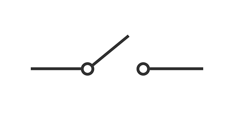
open circuit defn
a break or gap in a circuit path where NO CURRENT can flow
voltage across the open terminals can be any value
ex. a switch that’s turned off, a cut wire, battery removed from device.
open circuit symbol
short circuit (mathematically)
i = VERY HIGH (can be dangerously high)
v = 0 V
R = very low / ideally 0
short circuit defn
unintended low-resistance path in a circuit that allows current to flow along a SHORTCUT instead of the correct path (NOT desired)
happens when 2 terminals in a circuit that should be at diff voltages are connected directly w vv little/0 R
the low R means that a VERY LARGE current can flow, which can cause overheating/damage/fires
ex. bare wires touching where they shouldn’t, damaged insulation causing wires to connect directly
short circuit symbol
see notes
ideal voltage source symbol
see notes
ideal current source symbol
see notes
voltmeter
an instrument used to measure the diff in elec pot b/w 2 points in a circuit.
has vv high internal R so it doesn’t draw significant current from the circuit
an IDEAL voltmeter would have no current flowing in it at all.
if R → very large, then current → ______
very small, bc resistance OPPOSES THE FLOW OF CURRENT
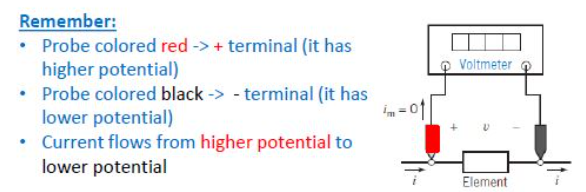
illustration of a voltmeter
connect red probe to positive terminal (where it has higher electric potential)
connect black probe to negative terminal (where it has lower elec pot)
current would flow from higher pot → lower pot
voltage is measured ACROSS an element so it is connected in || to the elem
how to read a voltmeter
RMBR: vrb = vred - vblack
rmbr that the voltmeter gives you the elec pot DIFFERENCE
if the voltmeter’s reading of the elec pot diff is pos, then terminal connected to the red probe is at a higher elec pot
if neg, the terminal connected to the red probe is at a lower elec pot → this means our assumption of which terminal had higher potential was wrong.
ammeter
an instrument used to measure the current flowing thru a branch of a circuit
vv low internal R so that current can pass through easily (current always favours the path of least R)
an IDEAL ammeter would have a voltage of 0
if R → very small, then i → _____
very large
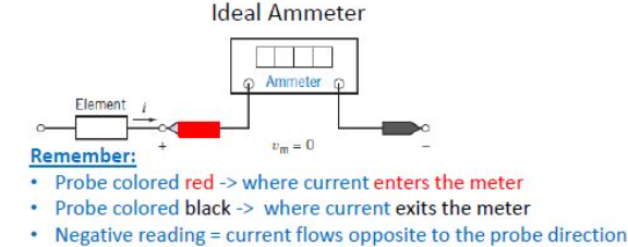
illustration of an ammeter
red probe: where we assume current enters
black probe: where we assume current leaves
unlike a voltmeter, an ammeter must be placed in SERIES after the elem we want to analyze
how to read a ammeter
pos reading: the current flows in the direction of the probes (enters the red probe and leaves through the black probe) → adheres to passive convention
neg reading: the current flows oppo to the probe dir (enters the black probe and leaves through red probe) → does not adhere to passive convention.
an ammeter would not give a reading if a current does not go through it COMPLETELY.
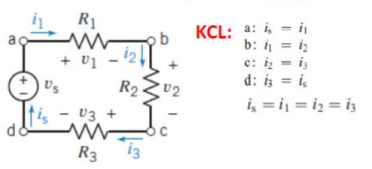
KCL (Kirchhoff’s Current Law)
defn: the sum of currents entering a node/junction = the sum of currents leaving the node/junction
this is why i is the same througout a purely series circuit (see image)
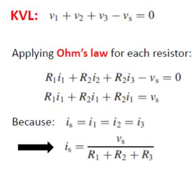
KVL (Kirchhoff’s Voltage Law)
defn: the algebraic sum of all voltages around any CLOSED LOOP = 0 (the gains and losses of voltage add up to 0)
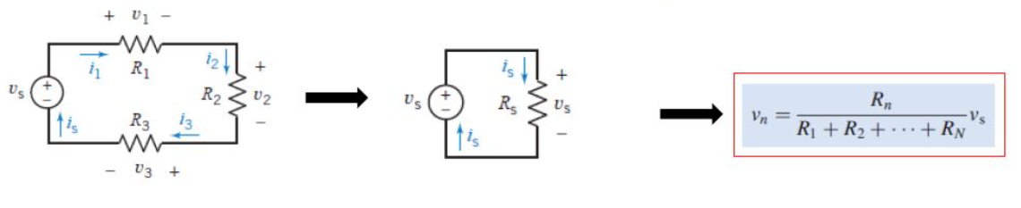
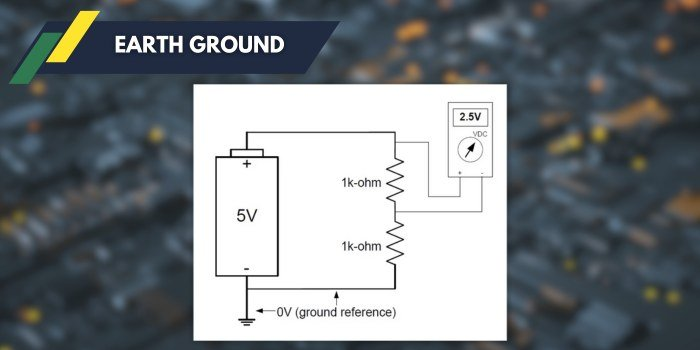
Voltage Divider Rule
voltage drop across an elem is directly proportional to the elem’s resistance.
you can ONLY use vsource in formula
ONLY applies to series circuits.
a __________ pushes current thru an elem
voltage drop
earth ground
the reference point in a circuit where voltage = 0 and all the potential has been “used up”
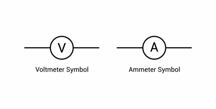
simplified universal symbols for voltmeter + ammeter
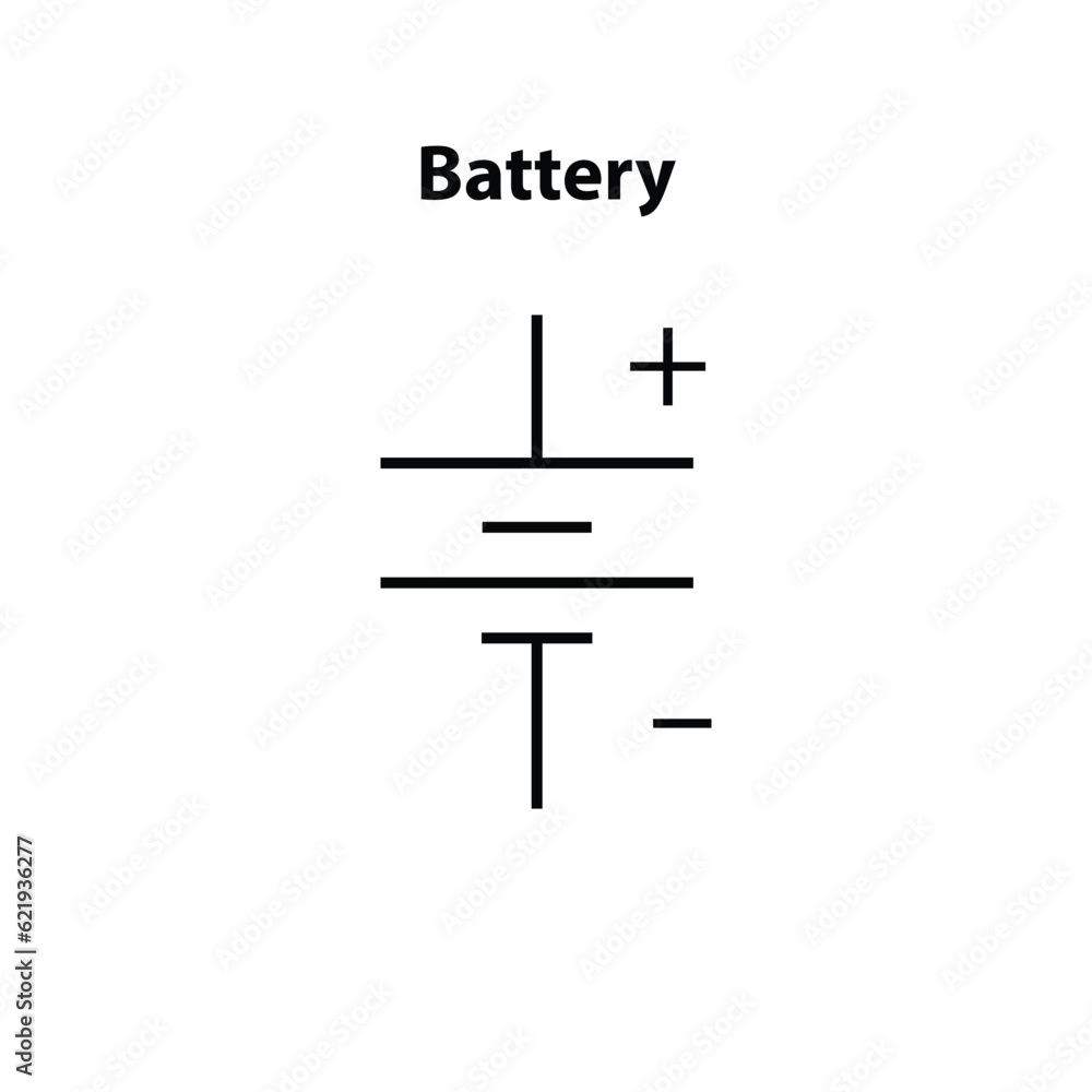
universal symbol for battery
pos end is always the longer end
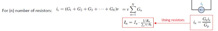
current divider rule
current is divided in a parallel circuit
current is separated at a node
the formula is simpler with G (conductance) instead of R → recall that G = 1/R
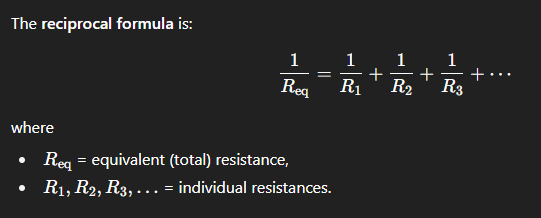
formula for adding resistances that are in PARALLEL with each other
(or you could convert to G for an easier computation)